HAL Id: hal-02136627
https://hal.archives-ouvertes.fr/hal-02136627
Submitted on 22 May 2019
HAL is a multi-disciplinary open access
archive for the deposit and dissemination of
sci-entific research documents, whether they are
pub-lished or not. The documents may come from
teaching and research institutions in France or
abroad, or from public or private research centers.
L’archive ouverte pluridisciplinaire HAL, est
destinée au dépôt et à la diffusion de documents
scientifiques de niveau recherche, publiés ou non,
émanant des établissements d’enseignement et de
recherche français ou étrangers, des laboratoires
publics ou privés.
Adding a rate-1 third dimension to turbo codes
Claude Berrou, Alexandre Graell I Amat, Youssouf Ould Cheikh
Mouhamedou, Catherine Douillard, Yannick Saouter
To cite this version:
Claude Berrou, Alexandre Graell I Amat, Youssouf Ould Cheikh Mouhamedou, Catherine Douillard,
Yannick Saouter. Adding a rate-1 third dimension to turbo codes. ITW 2007 : IEEE Information
Theory Workshop, Sep 2007, Lake Tahoe, United States. pp.156 - 161, �10.1109/ITW.2007.4313066�.
�hal-02136627�
Adding a Rate-1 Third Dimension to Turbo Codes
C. Berrou, A. Graell i Amat
1, Y. Ould Cheikh Mouhamedou, C. Douillard, and Y. Saouter
GET-ENST Bretagne. Electronics Department/PRACOM. CS 83818 - 29238 Brest Cedex 3, France. email: {claude.berrou, alexandre.graell, youssouf.ouldcheikh, catherine.douillard, yannik.sauter}@enst-bretagne.fr
Abstract— Thanks to the message passing principle, turbo decoding is able to provide strong error correction near the theoretical (Shannon) limit. However, the minimum Hamming distance (MHD) of a Turbo Code may not be sufficient to prevent a detrimental change in the error rate vs. signal to noise ratio curve, the so-called flattening. Increasing the MHD of a Turbo Code may involve using component encoders with a large number of states, devising more sophisticated internal permutations, or increasing the dimension of the Turbo Code, i.e. the number of component encoders. This paper addresses the latter option and proposes a modified Turbo Code, in which some of the parity bits stemming from the classical component encoders are encoded by a rate-1, third encoder. The result is a significantly increased MHD, which improves turbo decoder performance at low error rates, at the expense of a very small increase in complexity. In the paper, we compare the performance of the proposed Turbo Code with that of the DVB-RCS Turbo Code and the DVB-S2 LDPC code.
I. INTRODUCTION
Turbo Codes (TCs) are today mainly used in Automatic ReQuest (ARQ) systems, which do not usually require very low error rates. Target Frame Error Rates (FER) from 10−2to
10−5are typical for this kind of communication systems. Most
of current commercial applications of TCs, such as Digital Video Broadcasting standard [1], and the 802.16a WiMAX standard for local and metropolitan area networks [2], are based on 8-state component encoders. While such codes offer performance close to the Shannon limit in the so-called
wa-terfall region, they suffer from a flattening around FER 10−5,
due to a poor minimum Hamming distance (MHD). In future system generations, lower error rates, down to 10−8, will be
required to open the way to real-time and more demanding applications, such as TV broadcasting or videoconferencing. Therefore, state-of-the-art 8-state TCs are not suitable for these kind of applications, but more powerful coding schemes are required. At the same time, a reasonable complexity should be preserved.
Improving performance at very low error rates by raising the MHD may involve using component encoders with a larger number of states, devising more appropriate internal permutations, or increasing the dimension of the TC, i.e. the number of component encoders. More complex 16-state TCs have already been adopted in some standards. A very powerful TC based on 16-state components, achieving FERs down to 10−7for a wide range of code rates has been recently proposed
in [3]. The price is paid in terms of complexity, which
1A. Graell i Amat is supported by a Marie Curie Intra-European Fellowship
within the 6th European Community Framework Programme.
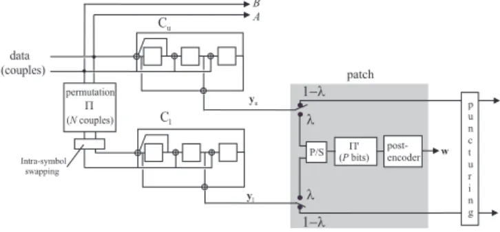
B A d a t a ( c o u p l e s ) C u C l yl p e r m u t a t i o n P ( N c o u p l e s ) yu p a t c h P / S ( P b i t s )P ' p o s t -e n c o d e r w p u n c t u r i n g I n t r a - s y m b o l s w a p p i n g 1 - l 1 - l l l
Fig. 1. The proposed 3D Turbo Code: two fractions λ of the parity bits stemming from both component encoders are grouped by a parallel to serial (P/S) multiplexer, permuted by permutation Π0 and re-encoded by a rate-1
post-encoder.
is doubled w.r.t. 8-state components TCs. Designing better permutations is another alternative to improve the minimum distance of TCs. Recently proposed DRP [4] and ARP [5] permutations are very simple models which allow to achieve very high distances. Devising better interleavers seems to be a very difficult and time consuming task.
This paper addresses the third alternative to improve TCs performance, and proposes a three-dimension Turbo Code (3D-TC), simply derived from the classical TC by concatenat-ing a post-encoder at its output. Thanks to the message passconcatenat-ing (turbo) principle, it has become simple today to imagine various coding structures, by concatenating simple component codes, provided that their corresponding decoders are of the Soft-In/Soft-Out (SISO) type. Basically, there are two kinds of concatenation: serial and parallel. Mixed structures are also possible, like the ones proposed in [6] or [7]. The 3D-TC we describe here is inspired by these contributions and calls for both parallel and serial concatenation.
The proposed code is very versatile and provides very low error rates for a wide range of block lengths and code rates. It significantly improves performance in the error floor w.r.t. the 8-state DB TC of the DVB-RCS standard, at the expense of a very small increase in complexity (less than 10%). Also, it compares favorably with respect to more complex 16-state TCs, and the LDPC code of the DVB-S2 standard.
II. THEENCODINGSTRUCTURE
A block diagram of the proposed 3D Turbo Code is de-picted in Fig. 1. The information sequence u of length k is grouped into couples of bits and encoded by the double-binary turbo encoder of the DVB-RCS standard [8]. The DVB-RCS
Turbo Code is built from the parallel concatenation of two 8-state recursive systematic convolutional (RSC) codes, with generator polynomials 15 (recursivity), 13 (redundancy), and 7 (second input). Note that the internal permutation Π deals with messages of N = k/2 symbols. The overall code rate (before puncturing) is 1/2. In Fig. 1 we denote Cu the upper
encoder and Cl the lower encoder. The corresponding parity
sequences are denoted yu and yl, respectively.
A fraction λ (0 ≤ λ ≤ 1) of the parity bits stemming from each component encoder are post-encoded by a rate-1, third encoder. In the sequel, we shall refer to λ as the permeability rate. The bits to be post-encoded are chosen in a regular basis. For instance, if λ = 0.25 the permeability pattern is 1000 for both the upper and the lower encoders, i.e., every forth bit in yu and yl is post-encoded. Finally, the input sequence of
the post-encoder is made of alternate yu and yl (surviving)
parity bits. The number of parity bits which are fed to the post-encoder is given by:
P = 2λN = λk, (1)
The fraction 1 − λ of parity bits which is not re-encoded is sent directly to the channel or punctured to achieve the desired code rate.
The material added to the classical turbo encoder, which we call the patch because it is placed just behind a pre-existing turbo encoder, is composed of:
• a parallel to serial (P/S) multiplexer which takes
alter-nately the parity bits y1 and y2 to be re-encoded and
groups them into a single block of P bits,
• a permutation denoted Π’ which permutes the parity bits
before feeding them to the post encoder,
• a rate-1 post-encoder whose output is denoted w.
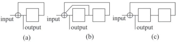
The value of λ to be chosen is a matter of trade-off between the convergence loss and the required MHD. Convergence designates the zone of the error rate vs. signal to noise ratio (SNR) curve where the error rate begins to decrease noticeably. Choosing a large value of λ penalizes the decoder from the convergence point of view. This results from the decoder associated with the post-encoder, which does not benefit from any redundant information at the first iteration and therefore multiplies the errors during the first processing. Let us assume for instance that the post-encoder is the well-known accumulator (i.e. convolutional code with memory 1), depicted in Fig. 3(a). The associated decoder (the pre-decoder), without any extra information, doubles the errors at its input. From (1), the fraction θ of the codeword bits that are post-encoded bits is:
θ = P
n = λR, (2)
where n is the codeword length and R is the coding rate of the 3D turbo code. The fraction θq of the data processed by
the component decoder of each code Cq, (q = 1, 2), that is
processed by the pre-decoder is:
θq= λR 1 + R. (3) i n p u t o u t p u t i n p u t o u t p u t ( a ) ( c ) i n p u t o u t p u t ( b )
Fig. 2. Possible linear post-encoder candidates, with memory 1 or 2.
Then, if p is the probability of error at the channel output, the average probability of error p0 at each decoder intrinsic
input is: p0= 2θ qp + (1 − θq)p = (1 + θq)p. (4) Using (3) we get p0= µ 1 + (1 + λ)R 1 + R ¶ p (5)
i.e. the probability of error at each decoder intrinsic input is
risen by a factor ³
1+(1+λ)R 1+R
´
, inducing a loss in convergence. On the other hand, a large value of λ will translate into a higher MHD.
The strategy for choosing the permeability rate λ ensues directly from (5):
1) for a given acceptable convergence loss and for the curve
p(EbN0) (for instance, erfc(x) for a Gaussian channel),
infer the value of p0
p =
1+(1+λ)R 1+R .
2) For a given coding rate, deduce the value of λ.
3) If the resulting MHD is not sufficient, increase p0 and
go to (1).
Note that the rate of the 3D Tubo Code is necessarily upper bounded by 1
1+λ.
III. THECHOICE OF THEPOST-ENCODER
The choice of the post-encoder is crucial for code perfor-mance. It has to meet the following requirements:
1) Its decoder must be simple, adding little complexity to the classical turbo decoder, while being able to handle soft-in and soft-out information,
2) in order to prevent the decoder suffering from any side effects, because very low error rates are sought for, the post-code has to be a homogeneous block code,
3) at the first iteration (so, without any redundant input information), the pre-decoder associated with the rate-1 post-encoder must not exhibit too much error amplifica-tion, to prevent from a high loss in convergence. Possible candidates, low memory linear RSC codes which satisfy condition (1), are given in Fig. 2.
Condition (2) is compatible with the use of Circular RSC (CRSC) codes having memory 2. Circular convolutional codes (also called tail-biting codes), are such that any state of the encoder register is allowed as the initial state and that the encoding always starts and ends in the same state. This makes the convolutional code a perfect block code and prevents it from any side effects. Moreover, no rate loss is induced by terminating the code. Circular CCs have already been adopted
d i
s
1 , is
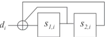
2 , iFig. 3. Linear Feedback Register (LFR) with memory 2 and recursivity polynomial 7 (octal).
in the DVB-RCS turbo code. Note that the code with memory 1 (the accumulate code, Fig. 2a) cannot be made circular by applying state mapping described in eqs. (14-15), and has to be discarded. Code (b) in Fig. 2 can easily be made circular, provided that the number of bits to be encoded is not a multiple of 3. On the other hand, at the first step of the iterative process, its decoder will (roughly) triple the number of errors of its input. Finally, code (c) has a corresponding decoder which only doubles the number of errors at the first step. Therefore, from the convergence point of view, it will be preferable to code (b).
Code (b) cannot be made circular directly. However, a simple trick will allow us to use this code as a CRSC code, as explained below.
A. Generalities on CRSC Codes
Let si and di be the state of the encoder register, and the
encoder data input, respectively, at discrete time i. The encoder state at time i + 1 is given by the following equation:
si+1= Gsi+ di, (6)
where G is the state matrix of the linear feedback register (LFR). For instance, considering the LFR in Fig. 3, whose binary input is denoted di, we have:
si= · s1,i s2,i ¸ , di= · di 0 ¸ , G = · 1 1 1 0 ¸ . (7) More generally, for a memory ν register, vectors si and di
have ν components and G is of size ν × ν. After the encoding of the data sequence {di}, of length P , the final state sp can
be expressed as a function of initial state s0 and {di}:
sP = GPs0+ P X j=1 GP −jd j−1. (8)
If it is possible to find a circulation state, denoted sc, such
that sc= s
0= sP, this is given by:
sc=£I + GP¤−1 P X j=1 GP −jd j−1, (9)
where I is the ν × ν identity matrix.
Note that sc exists if and only if I + GP is invertible. This
condition is never satisfied for some matrices G, whatever P . This is the case of the encoders of Fig. 2(a) and Fig. 2(c), which have G = [1] and G =
· 1 0 0 1
¸
, respectively. For other matrices, I + GP is invertible if P is not a multiple of
the period L of the LFR, defined by GL = I. For instance,
the LFR in Fig. 2(b) has L = 3. Therefore, I + GP is not
invertible for P = 3m, being m and integer. In such cases, the encoder cannot directly be made circular.
Before the encoding of {di}, the knowledge of sc requires
a preliminary step. The encoder is first set up in the all-zero state, and then fed by the data sequence {di}. The final state
is denoted s0 P. From (8), we have s0 P = P X j=1 GP −jd j−1, (10)
and, from (9), sc can be related to s0 P by:
sc=£I + GP¤−1s0P. (11)
Finally, the encoder being initialized to the circulation state, the encoding process can really start to provide the redundancy sequence.
B. The post-encoder with generator polynomial 5
The encoder of Fig. 2(c) can be made circular by introduc-ing some modifications in the principle above. Let us transform the final state given by (8) into:
s0P = AsP, (12) where A = · 1 1 0 1 ¸ if P odd A = · 1 1 1 0 ¸ if P even (13) We then have: s0 P = AGPs0+ A P X j=1 GP −jd j−1, (14)
Under these conditions, a circulation state (sc = s
0= s0P)
always exists, and it is given by: sc = B P X j=1 GP −jdj−1= Bs0p, (15) with B =£I + AGP¤−1A (16)
Note that, because of G = ·
0 1 1 0
¸
, and thanks to the values assigned to A, I + AGP is always invertible.
The encoding procedure can now be described by the following steps:
1) set up the encoder at the all-zero state. Feed it with {di}
and compute the final state s0 P,
2) calculate sc through (15) and (16),
3) encode {di} starting from sc. If needed, use (12) to
transform the final state, in order to verify that the result is sc.
The decoding process has to take transformation (12) into account. This is done by an exchange of metrics after having
i n p u t
o u t p u t
Fig. 4. The non-linear encoder derived from the encoder of Fig. 2(c).
processed address i = P , during the forward recursion, and after having processed address i = 1, during the backward recursion, when the MAP algorithm, or a simplified version, is employed. Table 1 provides the corresponding values of sp
and s0
p, obtained through (12) and the corresponding values of
s0
p and sc, obtained through (15). We can observe that only 2
(if P is odd) or 3 (if P is even) metrics need to be swapped during the decoding process, at the extremity of the block, which represents a very small additional complexity for the 4-state decoder.
For short block sizes (k < 1000 bit) and for medium sizes (1000 < k < 5000) with low rates, the linear post-encoder of Fig. 2(c) was chosen. However, for large blocks (5000 >
k) and for medium sizes with high rates, the 3D-TC with
post-encoder (c) shows a flattening around FER=10−6, due
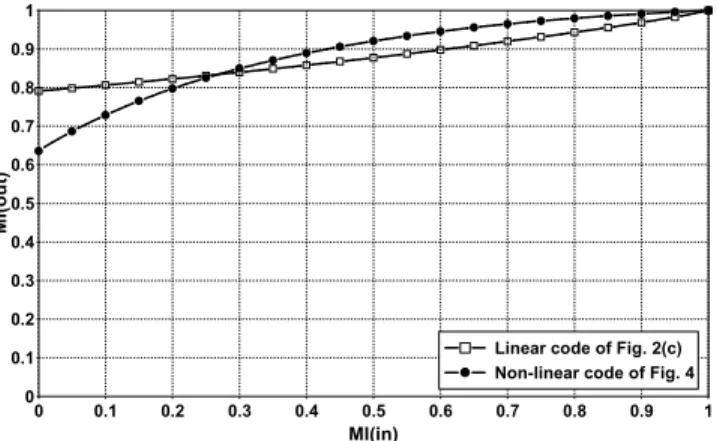
to a poor minimum distance. In these cases, the post-encoder was turned into the non-linear encoder depicted in Fig. 4. In Fig. 5 we report the EXIT curves for the linear post-encoder of Fig. 2(c) and the non-linear encoder of Fig. 4. When no a-priori information is available at the input of the pre-decoder (i.e. first iteration) the Mutual Information (MI) at its output is higher for the linear encoder. In fact, the linear post-encoder doubles the the number of error at the first iteration, while the non-linear post-encoder multiplies the the number of error by a factor 3−4. Therefore, the properties of this code do not seem very appropriate with respect to condition (3) in the choice of the post-encoder. However, the two curves in Fig. 5 cross around input MI 0.3. For high input MI the behavior of the non-linear code is better, indicating a better behavior in the floor region. The non-linear encoder contributes to increase the MHD of the 3D-TC, with favorable consequences in the cases cited above.
IV. PERMUTATIONSΠANDΠ0
The proposed 3D-TC is characterized by two permutations, denoted Π and Π0. Π is the internal permutation of the DB-TC.
Here, we consider Π to be of the Almost Regular Permutation (ARP) type, as described in [?]. The ARP permutation is a generalization of the permutation model used in the DVB-RCS turbo code. A second permutation Π0 is used to spread
the parity bits before post-encoding. We assume Π0 to be the
simplest one. Denote i (1 ≤ i ≤ P ) and j (1 ≤ j ≤ P ) the address in the natural order and in the permuted order, respectively. Then, Π0 is defined by the following congruence
relation: i = Π0(j) = P0j + i0 mod P, (17) 0 0.1 0.2 0.3 0.4 0.5 0.6 0.7 0.8 0.9 1 MI(in) 0 0.1 0.2 0.3 0.4 0.5 0.6 0.7 0.8 0.9 1 M I( o u t)
Linear code of Fig. 2(c) Non-linear code of Fig. 4
Fig. 5. EXIT curves for the linear and non-linear post-encoders.
ru 8 - s t a t e S I S O D E C 1 P P P - 1 rl 8 - s t a t e S I S O D E C 2 a , b 4 - s t a t e S I S O P R E - D E C rw P '- 1 S / P 2 P / S P ' e x t r i n s i c i n f o r m a t i o n a b o u t A , B e x t r i n s i c i n f o r m a t i o n a b o u t yu a n d yl
Fig. 6. Block diagram of the 3D turbo decoder.
where i0 is the starting index, and mcd(P0, P ) = 1.
Note that the two permutations assumed in this paper are based on very simple models, enabling large degrees of parallelism.
V. DECODING THE3D TURBOCODE
The decoding of the 3D TC calls for the classical turbo procedure, as depicted in Fig. 6, in the logarithmic domain. As for standard TCs, the two 8-state SISO decoders (DEC1 and DEC2) exchange extrinsic information on the systematic bits (A, B in Fig. 1) of the received codeword. Also, they must provide the 4-state SISO pre-decoder (PRE-DEC) with extrinsic information on the post-encoded parity bits. In turn, the pre-decoder feeds the 8-state decoders with extrinsic information on these parity bits.
Because DEC1 and DEC2 are quaternary 8-state decoders processing N = k/2 couples of bits and the pre-decoder is a binary 4-state decoder processing P = λk data, the relative computational complexity added by the latter is very small. For instance, with λ = 1/4, the additional complexity is only 6%. To this, however, some extra-functions must be added to the classical turbo decoder, the main one being the calculation of the extrinsic information on parity bits to be fed to the pre-decoder. Overall, the additional complexity, compared to the
C Y1 i n p u t o u t p u t Y2 Y3
Fig. 7. The component double-binary encoder with three outputs.
0 0.5 1 1.5 2 2.5 3 3.5 4 4.5 5 Eb/N0 (dB) 100 10-1 10-2 10-3 10-4 10-5 10-6 10-7 10-8 10-9 F E R 3D-TC DVB-RCS TC 16-state DB TC [7] Theoretical Limit k=188 bytes R=1/4 R=1/2 R=4/5
Fig. 8. Performance, in Frame Error Rate, of the 3D-TC with λ = 1/4 for k = 188 bytes, R = 1/4, 1/2 (linear post-encoder) and 4/5 (non-linear post-encoder) and comparison with the DVB-RCS TC. All simulations used the Max-Log-MAP algorithm with 8 iterations. TL: theoretical limit (sphere packing bound).
classical turbo decoder, is less than 10% for λ = 1/4. VI. SIMULATIONRESULTS
The performance of the 3D-TC was assessed by means of simulation. In Figs. 8 and 9 we report frame error rate results for two typical block sizes, 188 and 57 bytes, respectively, and coding rates 1/4, 1/2 and 4/5. In all simulations λ = 1/4 and a maximum of 8 iterations are assumed. The component decoding algorithm is the simple Max-Log-MAP algorithm (also called the dual Viterbi algorithm). Note that for global coding rate 1/4, the component double-binary encoder in Fig. 1 has to output three parity bits. Fig. 7 depicts the block diagram of the best 8-state encoder that was found to provide three outputs.
The proposed code shows excellent performance for both short and medium block sizes. In particular, for information block size 188 bytes (see Fig. 8) only 0.8 dB loss is observed with respect to the sphere packing bound at 10−7for all rates.
For comparison purpose, the performance of the original DVB-RCS TC is also reported for rates 1/2 and 4/5. As expected, in most cases (except for R = 4/5) the 3D-TC shows a small convergence loss at high error rates with respect to the DVB-RCS TC. On the other hand, the error floor is significantly improved. The largest gain is obtained for 188 bytes and R = 1/2 (about 1.4 dB at FER= 10−7). The performance of the
1 1.5 2 2.5 3 3.5 4 4.5 5 5.5 6 Eb/N0 (dB) 100 10-1 10-2 10-3 10-4 10-5 10-6 10-7 10-8 10-9 F E R 3D-TC DVB-RCS TC 16-state DB TC [7] Theoretical Limit k=57 bytes R=1/4 R=1/2 R=4/5
Fig. 9. Performance, in Frame Error Rate, of the 3D-TC with λ = 1/4 for
k = 57 bytes, R = 1/4, 1/2 and 4/5 (linear post-encoder) and comparison
with the DVB-RCS TC. All simulations used the Max-Log-MAP algorithm with 8 iterations. TL: theoretical limit (sphere packing bound).
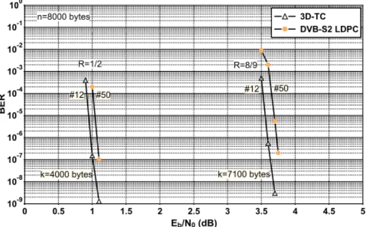
0 0.5 1 1.5 2 2.5 3 3.5 4 4.5 5 Eb/N0 (dB) 100 10-1 10-2 10-3 10-4 10-5 10-6 10-7 10-8 10-9 B E R 3D-TC DVB-S2 LDPC n=8000 bytes R=1/2 R=8/9 #12 #50 k=4000 bytes #12 #50 k=7100 bytes
Fig. 10. Performance, in Bit Error Rate, of the 3D-TC with l = 1/8 for n = 8000 bytes, R = 1/2 and 8/9 (non-linear post-encoder) and comparison with the DVB-S2 LDPC code performance. The number of iterations was 12 for the 3D-TC (using the Max-Log-MAP algorithm) and 50 for the LDPC. The LDPC performance was obtained from an FPGA (courtesy of TurboConcept) while the 3D-TC decoder operated on real channel values (i.e. no quantization).
3D 8-state TC is comparable to that of much more complex 16-state TCs, such as the one described in [3], also reported in the Figs. 8 and 9 for rates 1/2 and 4/5. For a block length of 188, the 3D-TC looses 0.1 dB in convergence w.r.t. the 16-state double-binary Turbo Code in [3]. However, the proposed code improves the 16-state TC in the error floor. A similar behavior is observed in Fig. 9 for a block length of 57 bytes. The proposed code also shows very good performance for large block lengths. In Fig. 10 the bit error rate performance (BER) of the proposed 3D-TC is compared with that of the DVB-S2 standard LDPC code [9], for coding rates 1/2 and 8/9 and a coded block length of 8000 bytes. Here, λ = 1/8 and 12 iterations are assumed for the 3D-TC. Similar performance are observed for the two codes. To the best of our knowledge, this is the first time that a (modified) turbo code achieves such a performance for a long block and a 8/9 coding rate.
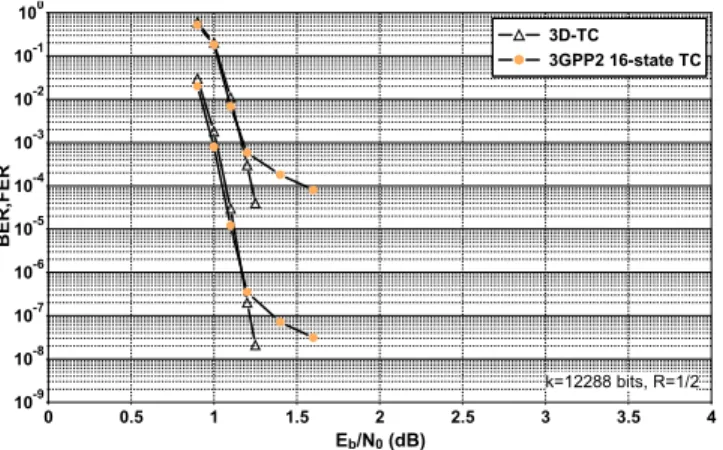
0 0.5 1 1.5 2 2.5 3 3.5 4 Eb/N0 (dB) 100 10-1 10-2 10-3 10-4 10-5 10-6 10-7 10-8 10-9 B E R ,F E R 3D-TC 3GPP2 16-state TC k=12288 bits, R=1/2
Fig. 11. Performance, in Bit Error Rate, of the 3D-TC with l = 1/8 for n = 8000 bytes, R = 1/2 and 8/9 (non-linear post-encoder) and comparison with the DVB-S2 LDPC code performance. The number of iterations was 12 for the 3D-TC (using the Max-Log-MAP algorithm) and 50 for the LDPC. The LDPC performance was obtained from an FPGA (courtesy of TurboConcept) while the 3D-TC decoder operated on real channel values (i.e. no quantization).
Finally, in Fig. 11 performance comparison is given w.r.t. the 16-state TC adopted in the 3GPP2 standard. An informa-tion block length of 12288 bits and 8 iterainforma-tions are assumed for the two codes. Very similar performance are observed in the waterfall region. However, the proposed 3D-TC signifi-cantly improves the 3GPP2 code in the floor. No flattening is observed at FER 10−5. Also note that the complexity of the
proposed code is noticeably lower. VII. CONCLUSIONS
In this paper, we presented a modified turbo code combining the features of parallel and serial concatenation in order to obtain increased Hamming minimum distances compared to those of classical turbo codes. The simulation results corrob-orate the interest of this approach. Frame error rates down to 10−7are obtained near the theoretical limits without the use of
any outer block code, such as BCH or Reed-Solomon codes. This characteristic makes this new code, called 3D turbo code (3D-TC), very versatile from the standpoint of block size and coding rate. Furthermore, the component decoding algorithm (Max-Log-MAP) is simple and does not require the knowledge of the channel. Finally, the internal permutations of the 3D-TC are based on very simple models enabling large degrees of parallelism, if needed.
REFERENCES
[1] Interaction channel for satellite distribution systems. DVB, ETSI EN 301
790, vol. 1.2.2, 2000.
[2] IEEE standard for local and metropolitan area networks. IEEE 802.16a,
2003.
[3] C. Douillard, and C. Berrou, “Turbo Codes with Rate-m/(m + 1)
Constituent Convolutional Codes,” IEEE Trans. Commun., vol. 53, no. 10, pp. 1630-1638, Oct. 2005.
[4] S. Crozier, and P. Guinand, “High-performance Low-memory
Inter-leaver Banks for Turbo-codes,” in Proc. 54th IEEE Vehic. Tech. Conf. (VCT?01), pp. 2394-2398, Oct. 2001.
[5] C. Berrou, Y. Saouter, C. Douillard, S. Keroudan, and M. Jzquel,
“Designing good permutations for turbo codes: towards a single model,” in Proc. IEEE Int. Conf. Commun., Paris, France, June 2004.
[6] J. Li, K. R. Narayanan, and C. N. Georghiades, ”Product Accumulate
Codes: A Class of Codes With Near-Capacity Performance and Low Decoding Complexity”, IEEE Trans. Inform. Theory, vol. 50, no.1, pp. 31-46, Jan. 2004.
[7] H. Gonzalez, C. Berrou, and S. Keroudan, “Serial/Parallel Turbo Codes
for Low Error Rates”, in Proc. IEEE Int. Conf. Commun., Paris, France, June 2004.
[8] C. Berrou, “The Ten-Year-Old Turbo Codes are Entering into Service,”
IEEE Comm. Mag., pp. 110-116, Aug. 2003.
[9] European Telecommunications Standards Institude (ETSI). Digital Video
Broadcasting (DVB) Second generation framing structure for broadband satellite applications. EN 302 307 V1.1.1, 2005.