HAL Id: hal-00288132
https://hal.archives-ouvertes.fr/hal-00288132
Submitted on 7 Oct 2008
HAL is a multi-disciplinary open access
archive for the deposit and dissemination of
sci-entific research documents, whether they are
pub-lished or not. The documents may come from
teaching and research institutions in France or
abroad, or from public or private research centers.
L’archive ouverte pluridisciplinaire HAL, est
destinée au dépôt et à la diffusion de documents
scientifiques de niveau recherche, publiés ou non,
émanant des établissements d’enseignement et de
recherche français ou étrangers, des laboratoires
publics ou privés.
Load repartition for congestion control in multimedia
wireless sensor networks with multipath routing
Moufida Maimour, Cong-Duc Pham, Julien Amelot
To cite this version:
Moufida Maimour, Cong-Duc Pham, Julien Amelot.
Load repartition for congestion
con-trol in multimedia wireless sensor networks with multipath routing.
3rd International
Sympo-sium on Wireless Pervasive Computing, ISWPC 2008, May 2008, Santorini, Greece.
pp.11-15,
�10.1109/ISWPC.2008.4556156�. �hal-00288132�
Load Repartition for Congestion Control in
Multimedia Wireless Sensor Networks with
Multipath Routing
Moufida Maimour
CRAN, Nancy University, CNRS Moufida.Maimour@cran.uhp-nancy.fr
C. Pham
LIUPPA, University of Pau, France Congduc.Pham@univ-pau.fr
Julien Amelot
CRAN, Nancy University, CNRS Julien.Amelot@esial.uhp-nancy.fr
Abstract— Wireless sensor networks hold a great potential in the deployment of several applications of a paramount impor-tance in our daily life. Video sensors are able to improve a number of these applications where new approaches adapted to both wireless sensor networks and video transport specific characteristics are required. The aim of this work is to provide the necessary bandwidth and to alleviate the congestion problem to video streaming. In this paper, we investigate various load repartition strategies for congestion control mechanism on top of a multipath routing feature. Simulations are performed in order to get insight into the performances of our proposals.
Keywords : Congestion control, Multipath routing, Sensor
networks, Video transport.
I. INTRODUCTION
This paper addresses the problem of congestion control in wireless sensor networks (WSN). Congestion control in WSN is particularly difficult as a WSN can usually remain idle for a long period of time and then suddenly become active in response to a detected event, generating a large amount of information from the sources (sensors) to a sink. Even if an event is a few bytes long, the high number of events due to high reporting rates will rapidly create shortage of resources (buffer space, battery life) in the WSN leading to congestion and consequently packet/event drops.
In addition to traditional sensing network infrastructures, a wide range of emerging wireless sensor network applications for object detection, surveillance, recognition, localization, and tracking can be strengthened by introducing a visioning capa-bility. Nowadays, such applications are possible since low-power sensors equipped with a visioning component [8], [3] already exist. In these Wireless Multimedia Sensor Networks (WMSN) [5], congestion control is of prime importance due to the inherently high rate of injection of multimedia packets in the network (video traffic is in the order of 250 kbit/s to 500 kbit/s).
The problem of congestion control have been addressed in many works along with a transport layer protocol proposition. CODA [2], ESRT [10], RMST [9] are some of those proposi-tions to name a few. We believe that cross-layer design holds great potential for addressing video transport challenges. This work is a first step in this direction by addressing congestion control with a multi-path routing facility. In this paper, we investigate various load repartition strategies on top of a
multipath routing feature for congestion control. The target application is video transmission and in order to keep the video quality unchanged, we avoid decreasing the transmission rate. Instead, a video flow is split on multiple paths if there are some available. There have been many work on load balancing or repartition but none for the best of our knowledge has specifically been addressed for or been used on wireless sensor networks. This paper tries to show whether load repartition is useful or not, and if so, where are the expected gains.
The work presented recently in [6] is the closest to our proposition since their End-to-end Packet Scatter (EPS) split traffic on multiple paths, in an attempt to spread network load on a wider area based on the Biased Geographical Routing pro-tocol. However, the complexity of BGR that requires location features and of the congestion control mechanism that adds an In-Network-Packet-Scatter prior to the EPS mechanism is much higher than our proposition. EPS also is much more costly in terms of control messages. We only split the flows at the source and need less control feedback messages. We think that simplicity is of prime importance and should serve as a guideline when designing congestion control on WMSN.
The load repartition strategies vary from the simplest one which distributes uniformly the traffic on all available paths simultaneously to more complex strategies with explicit con-gestion notifications (CN) from congested nodes towards the sources. In these cases, on reception of a CN, a source will try to balance its traffic on available paths in order to keep its sending rate unchanged while reducing the amount of data sent on the current active paths. Congestion inferences could be based on the queue length at intermediary nodes such as in CODA or ESRT. At this point, we must state that the proposed solutions does not seek to obtain the optimal load repartition on all existing paths, but rather to react as quickly as possible to congestion to avoid packet losses in very resource-constrained devices. Therefore we plaid for a simple mechanism that limits both the number of exchanged control messages and the complexity at the sources.
The proposed mechanisms can be used with any multipath routing layer where explicit congestion notification, possibly implemented at a higher layer than the network layer, are available from intermediary nodes. However, in this paper, we study and propose the usage of SLiM (Simple Lifetime-based
Multipath routing protocol) that was previously described in [7] and that provides multipath routing from a set of sources to a given sink with a path’s lifetime criterion.
The paper is organized as follows. Section II presents the network model with the different assumptions considered in this work. The SLiM multipath routing protocol is also briefly presented for the purpose of making the paper self-reading. Section III presents the various load repartition strategies for congestion control on top of SLiM. Some simulation results are presented in section IV before concluding.
II. NETWORKMODEL
We consider a wireless sensor network with video sensors located in strategic locations and other non visual sensors distributed randomly in a field. A video sensor is asleep and is only waked up when alerted by other non visual sensors upon target detection or as a response to a request. In this paper we consider the case of multiple video sensors (referred to as the sources) being reporting video information to the sink at relatively the same time.
Video applications are considered as semi-reliable ones where some losses are tolerated but a minimum data rate is required from the beginning of the transmission. In order to be able to satisfy this requirement, we investigate the use of multiple paths so a maximum bandwidth can be supplied. Therefore, we assume that a multipath routing protocol is available. In this paper, we use SLiM [7] but any other multipath routing protocol able to build and maintain at the same time more than one path can be used by our congestion control scheme.
SLiM, with only local topology knowledge, provides to a source and all intermediary nodes the knowledge of all available paths to the sink. It adopts the sink-initiated approach where the sink is the originator of a request. The sink floods the network with a request until the sensor, referred to as the source, having the target in its field of view is reached. With one flooding, multiple paths are built and maintained at intermediate nodes towards the sink. In SLiM, a request is identified using a path id that corresponds to the first crossed sensor’s id from the sink to the source. Paths are built with respect to a quality metric specified by the application. This metric can be the path length, its available energy, an estimation of its lifetime or any other metric depending on the application requirements.
Each sensor is able to create, maintain and update a path table that records the different paths to the sink. The table contains an entry for each path with the following fields :
• pid, the path id,
• inUse, a flag, when set indicates that the corresponding
path is currently in use,
• nextNode, the next hop towards the sink on this path,
• quality, an estimation of the associated quality metric for
this path.
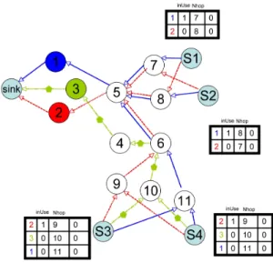
Fig. 1. Network model with multiple paths to the sink.
Figure 1 shows a configuration typically built by SLiM. This scenario shows 15 sensor nodes and 1 sink. Among the 15 sensor nodes, there are 4 sources identified as S1, S2, S3 and S4. We can see that there are 3 different paths with path id 1, 2 and 3, named after the first crossed node’s id from the sink. S1 and S2 have path id 1 and 2 in their forwarding table. S3 and S4 have path id 1, 2, and 3 in their forwarding table. The right-most column keeps the rate repartition as will be explained later on. Note that SLiM avoids constructing different path id at a source with the same predecessor. This was done in order to limit congestion when no congestion control was defined on top of SLiM.
For what follows, the sink is never the bottleneck nor in term of bandwidth nor in term of energy. It can have its battery recharged or replaced in real applications. In contrast, all the sensors have limited energy, are supposed to be stationary but with the ability to dynamically vary their transmission power. We assume that an addressing scheme is available. Globally unique addresses can be very expensive in terms of bandwidth and power consumption. Instead we consider a local address-ing scheme as the one proposed in [1]. We use an address for a sensor that can be reused by an other one located sufficiently far away. We assume, however, a uniquely assigned address to the sink in order to distinguish it from the other sensors.
III. LOAD REPARTITION FOR CONGESTION CONTROL
In this paper we investigate the use of load repartition mechanisms for the purpose of congestion control. In figure 1, after SLiM has constructed the path configuration and forwarding tables, we assume that S1 and S2 use path id 1 as the default path whereas S3 and S4 use path id 2. This information is stored in the source’s forwarding table with the
inU se field. An additional field in the forwarding table keeps
the current data rate (or an estimation if the exact data rate is not known) sent on the path. We assume that each source stores paths in the order of decreasing quality.
A. Load repartition strategies
We define 3 load repartition strategies for congestion con-trol, from mode 1 to mode 3. For the purpose of comparison, mode 0 refers to the no load repartition scenario in which a source uses the same path (the best path in term of lifetime with SLiM) without any congestion control concerns. In mode 1 the source uses all the available paths to a sink from the beginning of the transmission. The traffic is then uniformly load-balanced on these paths. Mode 0 and mode 1 therefore represent the 2 end-points in the load repartition strategies design space.
In modes 2 and 3, explicit congestion notifications are used. At every intermediary node, when the reception queue occupancy is greater than a given threshold (80% of total buffer space for instance) or when the collision rate is above a given threshold, a Congestion Notification (CN) message is sent back to the sources for each path id known by the node. A CN message contains the node id and the path id: CN(nid, pid). For simplicity, we assume that each source sends 1 data flow identified by the source id. A sourceSi should react to
a CN message if the path id contained in the CN message corresponds to an active path in its local forwarding table. The basic principle behind these load repartition strategies is to make each source aware of a congestion on path i and
reacting to it by load-balancing the current traffic on this path on a larger number of paths. Selected paths at the source are then marked as active with the inU se flag, and the data rate
repartition for each path is kept in the forwarding table. In the following paragraphs, we will describe mode 2 and 3.
• Mode 2. The source starts initially with one path. For
each CN(nid, pid) message received, the source adds a new path (the first available path different frompid that is
non active) until all available paths are marked as active. The load is uniformly distributed on the number of active path. It is therefore an incremental approach.
• Mode 3. The source starts initially with one path. Upon
reception of a CN(nid, pid) message the source will uniformly balance the traffic of pathpid on all available
paths (including path pid). Therefore depending on the
number of CNs received for each path, the transmission rate is not the same on all the active paths as opposed to mode 2.
B. Detailed example of mode 3
In the scenario depicted by figure 2, each source sends a flow of events/messages to the sink. Therefore, according to the forwarding tables in each source, node 5 sees 4 flows. Assuming that flows from S1 and S2 are 50kbit/s flows and flows from S3 and S4 are 90kbit/s flows as shown in figure 2, node 5 has to relay a total data rate of 280kbit/s.
If we assume that such a data rate triggers 2 CN messages, CN(5,1) and CN(5,2), from node 5, sources S1 to S4 will receive them by means of the intermediate routing nodes. Upon reception of CN messages, each source will determine which CN message, if any, announces a congestion on an active path in its local forwarding table. For each active patha,
Fig. 2. Initial configuration, then congestion notification from node 5.
Siwill load-balance its current traffic ona on all the available
paths. In the scenario of figure 2, S1 and S2 will use path id 2 in addition to path id 1 on reception of CN(5,1), ignoring CN(5,2), and will send on each of these paths50/2 = 25kbit/s
of data. S3 and S4 will use 3 paths on reception of CN(5,2), and ignoring CN(5,1), by sending 90/3 = 30kbit/s of data
on each of those. Finally, we will end up with the data rate repartition shown in table I. Node 5 sees a total data rate of 25 + 25 + 25 + 25 + 30 + 30 + 30 + 30 = 220kbit/s
instead of 280kbit/s. Nodes 3, 4 and 10 (on path id 3) relay
30 + 30 = 60kbit/s from sources S3 and S4 (figure 3). At this
stage, with this scenario, mode 3 gives the same repartition than mode 2. path id S1 S2 S3 S4 total path id 1 25 25 30 30 110 path id 2 25 25 30 30 110 path id 3 30 30 60 total 50 50 90 90 280 TABLE I
RATE REPARTITION AFTER PROCESSINGCN(5,1)ANDCN(5,2).
Now, in figure 3, let us continue to assume that for some reason node 2 becomes congested (not shown in the figure). At this point, node 2 is relaying30+30+25+25 = 110kbit/s from
4 flows. In this case, S1 to S4 will receive a CN(2,2) that will trigger a new rate repartition. S1 and S2 will then load-balance uniformly their current traffic on path id 2 (25 for each from previous steps) on the 2 available paths. S3 and S4 will also load-balance uniformly their current traffic on path id 2 (30 for each from previous steps) on the 3 available paths. We have now the repartition illustrated in table II. Node 5 that previously sent a CN message now have a total data rate of
25+12.5+25+12.5+12.5+12.5+40+40+10+10 = 200kbit/s
Fig. 3. After congestion notification from node 5.
that path id 3 now carries a total traffic of40 + 40 = 80kbit/s
instead of 60kbit/s. path id S1 S2 S3 S4 total path id 1 25+12.5 25+12.5 40 40 155 path id 2 12.5 12.5 10 10 45 path id 3 40 40 80 total 50 50 90 90 280 TABLE II
RATE REPARTITION AFTER PROCESSINGCN(2,2).
IV. SIMULATIONRESULTS
The routing protocol and the different load repartition strate-gies were implemented with TOSSIM, the bit level simulator for TinyOS platform. We considered a square sensor field of size 1000 × 1000m2 where a given number of static sensor
nodes ranging from 50 to 250 with a step of 50 are randomly deployed. Each node has a maximum radio range. All the sensors have same processing capability. We adopted the energy model of [4] for transmission. The energy dissipation due to processing was neglected in our simulations. The sink is located at the upper right corner (coordinates 1000,1000) and an event occurrence is simulated at the opposite quarter of the field. Every video sensor located close enough to the event will start sensing and transmitting information towards the sink. Experiments were performed and averaged over 100 simulations with different randomly generated topologies (with radio range of 400m) and initial energies at the sensor nodes which are generated following a uniform distribution between
0 and 0.4 Joules.
Figure 4 shows the mean drop rate at the sensor queues as a function of the number of sensors for the various load repartition modes. In mode 0, the different sources transmit data with a fixed rate using only one path without any congestion control. Intermediate nodes, when overloaded, drop packets and hence the number of dropped packets is the
10 20 30 40 50 60 70 80 50 100 150 200 250 Message dropping Nodes number mode 0 mode 1 mode 2 mode 3
Fig. 4. Message dropping rate at sensor queues
largest compared to the other modes. Mode 1 gives the best performances with a dropping rate not more than 35%. This is due to the fact that the sources distribute their flows on all available paths from the beginning hence reducing the probability of overloaded queues. The other modes appears to have similar performances but less than mode 1. This is due to the fact that a source sends data on an other path only when it receives a CN. Meanwhile some packets can be dropped. However, we see that mode 3 that tries to balance the load of a congested path on the other paths does not succeed in reducing the drop rate when compared to a simpler approach such as mode 2, at least for small network size.
We also looked at the fairness among the sources in term of transmission rate when performing congestion control. The following commonly used formula:
(PNs i=1ri)2 Ns PNs i=1r2i (1) gives a fairness metric whereriis the success rate achieved by
sourcei and Nsis the number of sources. Figure 5 shows the
achieved fairness among the sources for the different modes as a function of the number of nodes. It appears that when using only one path per source (mode 0), fairness among sources is the worst. This is due to the fact that every source sends without any coordination since there is no congestion control. When distributing the flows on all available paths from the beginning (mode 1) without assessing the congestion situation, we eliminate any coordination between the sources and fairness among them is difficult to achieve. In modes 2 and 3, a form of implicit coordination is created among the sources since a congestion control mechanism using CN is carried out. We see that in mode 2 for example we achieve a fairness of more than 80% even for a large number of nodes. We also evaluated the load distribution among active sensors (i.e. those taking part in data forwarding). We used the same fairness metric but replaced the transmission rate by the amount of processed data at a given node. Figure 6 draws the load fairness among active sensors for the different modes.
0.3 0.4 0.5 0.6 0.7 0.8 0.9 1 50 100 150 200 250 Throughput fairness Nodes number mode 0 mode 1 mode 2 mode 3
Fig. 5. Rate fairness among sources
0 0.1 0.2 0.3 0.4 0.5 0.6 0.7 0.8 0.9 1 50 100 150 200 250 Load Fairness Nodes number mode 0 mode 1 mode 2 mode 3
Fig. 6. Load fairness among active sensors
Mode 0 achieves the best fairness since there is only one path and the load fairness is computed only for sensors belonging to this unique path. Distributing the flows on all the paths from the beginning (mode 1) does not appear to be interesting from a load distribution perspective. Mode 3 appears to have the best load distribution since we take into consideration the load on a per-path basis and then adjust accordingly the data rate on each active path.
Finally, we looked to assess the energy requirements of the different modes. Figure 7 shows the amount of consumed energy per correctly received packet at the sink. Naturally, mode 0 consumes less energy since, only one path is used and a small amount of data is received by the sink. Mode 1 consumes more energy per received packet than the other modes where load repartition mitigates congestion.
V. CONCLUSION
In this paper, we investigated the use of load repartition for congestion control of video flows in a wireless sensor network with multipath support. The motivation of this study is to maintain the video quality unchanged by splitting a video flow on multiple path instead of decreasing the
0.004 0.006 0.008 0.01 0.012 0.014 0.016 0.018 0.02 0.022 0.024 0.026 50 100 150 200 250
Mean Consumed Energy per Message
Nodes number mode 0
mode 1 mode 2 mode 3
Fig. 7. Mean consumed energy per received packet
mission rate. Various load repartition strategies are therefore proposed and evaluated. The preliminary results show that load repartition does improve congestion control by reducing the packet drop probability. Regarding fairness, which is a key factor in congestion control, the preliminary results show that even simple load repartition strategies can have a very high impact on performances. However, depending on the targeted video applications on the sensor network, one may choose to prefer either rate fairness among sources or load fairness among active sensors. More importantly, it has been shown that distributing the traffic on all the available path from the beginning is not efficient in term of energy nor in term of fairness.
REFERENCES
[1] M. Ali and Z. A. Uzmi. An energy-efficient node address naming scheme for wireless sensor networks. In IEEE International
Networking and Communications Conference (INCC’04), 2004.
[2] S. B. E. C.-Y. Wan and A. T. Campbell. Coda: Congestion detection and avoidance in sensor networks. In Proceedings of
ACM Sensys’03, 2003.
[3] W. chi Feng, B. Code, E. Kaiser, M. Shea, and W. chang Feng. Panoptes: A scalable architecture for video sensor networking applications. ACM Transactions on Multimedia Computing, Communications and Applications, January 2005.
[4] W. Heinzelman, A. Chandrakasan, and H. Balakrishnan. Energy-efficient communication protocol for wireless microsensor net-works. In Proceedings of the 33rd Hawaii International
Con-ference on System Sciences (HICSS ’00), January 2000.
[5] T. M. Ian F. Akyildiz and K. R. Chowdhury. A survey on wireless multimedia sensor networks. Computer Networks, 51, 2007.
[6] I. S. L. Popa, C. Raiciu and D. Rosenblum. Reducing congestion effects in wireless networks by multipath routing. In IEEE ICNP
2006, 2006.
[7] M. Maimour. Multipath routing protocol for layered video transport in wireless sensor networks. In Workshop on Wireless
Sensor Networks in conjunction with NOTERE 2007, Marrakesh,
Morocco, 2007.
[8] M. H. Rahimi, R. Baer, O. I. Iroezi, J. C. Garcia, J. Warrior, D. Estrin, and M. B. Srivastava. Cyclops: in situ image sensing and interpretation in wireless sensor networks. In SenSys, pages 192–204, 2005.
[9] F. Stann and J. Heidemann. Rmst: Reliable data transport in sensor networks. In Proceedings of IEEE SNPA’03, 2003.
[10] O. B. A. Y. Sankarasubramaniam and I. F. Akyidiz. Esrt: Event-to-sink reliable transport in wireless sensor networks. In