Publisher’s version / Version de l'éditeur:
Vous avez des questions? Nous pouvons vous aider. Pour communiquer directement avec un auteur, consultez la
première page de la revue dans laquelle son article a été publié afin de trouver ses coordonnées. Si vous n’arrivez pas à les repérer, communiquez avec nous à [email protected].
Questions? Contact the NRC Publications Archive team at
[email protected]. If you wish to email the authors directly, please see the first page of the publication for their contact information.
https://publications-cnrc.canada.ca/fra/droits
L’accès à ce site Web et l’utilisation de son contenu sont assujettis aux conditions présentées dans le site LISEZ CES CONDITIONS ATTENTIVEMENT AVANT D’UTILISER CE SITE WEB.
Canadian Conference on Electrical and Computer Engineering : Ten Years to
2000 [Proceedings], 1, pp. 14.4.1-14.4.5, 1990
READ THESE TERMS AND CONDITIONS CAREFULLY BEFORE USING THIS WEBSITE. https://nrc-publications.canada.ca/eng/copyright
NRC Publications Archive Record / Notice des Archives des publications du CNRC :
https://nrc-publications.canada.ca/eng/view/object/?id=5e63156c-b33f-48dc-ac62-cc39ac5fc89c
https://publications-cnrc.canada.ca/fra/voir/objet/?id=5e63156c-b33f-48dc-ac62-cc39ac5fc89c
NRC Publications Archive
Archives des publications du CNRC
This publication could be one of several versions: author’s original, accepted manuscript or the publisher’s version. / La version de cette publication peut être l’une des suivantes : la version prépublication de l’auteur, la version acceptée du manuscrit ou la version de l’éditeur.
Access and use of this website and the material on it are subject to the Terms and Conditions set forth at
Integration of regulatory codes with design systems
Canadian Conference on Electrical and Computer Engineering Congres canadien en genie electrique et infonnatique
Ottawa. Ontario. Canada.Sepcember J • 6 sepcembrc 1990
THE INTEGRATION OF REGULATORY CODES WITH DESIGN SYSTEMS
ABSTRACT
Steven M. Cornick, Debbie A. Leishman,
J.
Russell Thomas PhdAdvanced Construction Technology Laboralorj', lnstitme for Research in Construction.
National Research Council of Canada
of this general framework. A model of an lCAD systemis shown in Figure2.
The integration of regulatory codes within CAD design systems is important if designersaretousecomputers effectlvely m the deSIgn process. At present. regulations only implicitly conllUn models of objects within their scope andウセ「ウケウエ・セN These models need toセ
made explicit for incorporatlon mto mtelligent deSIgn systems. This paper outlines one way to incorporate these reference models. The. "oal is to develop systems that use both geomemc and non geomemc (technical and administrative) information aoom the desIgn processIn order to aid the designer in their task. To ensure a fleXIble system,11 is proposed that the reference models (objects in the design and the relationships between the objects) be separated from the techrncal requirements or constraints prescribed by the regulatlon.
INTRODUCTION GMmelrlc 1'1odo1. Non-,,"mltric O.t,
Figure1. A functional view of a mechanical CAD sySlClll [12].
Administrative knowledge is a key component of the knowledgebase One goal of research into lCAD systems is to facilitate the design that comprises a complete design. Information about previous design process by incorporating more of the designer'sォョッキャセ、ァ・ セ、 versions, related families of parts and manuiacruring processes are expertise into the system. This can be achieved by(l)Includmg examples of non-geometric information thatis crucial to the more domain specific knowledge, (2) uSing symbohc as well as successful implementation of a design.
numeric manipUlation. and (3) having interfaces suppon the use of Good design practice and economic arguments suggest that design knowledge as well as geomeuic data. An ICAD system regulations be incorporated into design systems to facilitate the. would be a general framework for incorporating knowledge about compliance process. A designer normally has regulations mmind geometry, technical iniormation (e.g.,.material propenies. functional when designing. However, complex regulations are often so requirements specificallons). and admirnsrranve reqUirements complex that individual designers are not cognizant of all relevant (standards, evolution and versions of design. related families. of . sections and must rely on more experienced persons to check for components. scheduling, inventory). Knowledge contained10thIS conformance. For example. a complex building can take uptofour general framework would be domaIn I.ndependent[1
J,
aXlOmanc months to undergo plan review. The incorporation of building . geometry bemg one example. Spectallzed or domaIn dependant regulations into an intelligent design subsystem could help to。カPQセ knowledge would then be 1I1corporated 1I1to subsystems bullt on tOp. ,the delays and costly errors that can occur when compliance checking14.4.1 REGULATORY INFORMATION Geometric 1'1odo1. Non-Geometric 001,
Figure 2. A model for an intelligentCAD sySlClll [12].
Uoer
The difference between this model of a CAD systemand that shown previouslyis the method by which the designer interfaces with the system, specifically through intelligent design subsystems. A planner monitors the evolving design and provides recommendations that guide the design activity. An intelligent design subsystem contains application-specific information appropriate to the area of design. A VLSI designer, for example, will deal with silicon. interconnection pathways, transistors. while an architectwilldesign with plaster, wood. and concrete. Each deals with different components, taxonomies. and design rules. Design subsystems are programs that contain fundamental design rules (e.g., depth=span / 16, for preliminary steel design). programs that refine preliminary designs (Door layout in steel design), interfaces10libraries of design examples. or programs that evaluate designs.
This paper will outline an approach by which the knowledge contained in a regulatory document can be mcorporated mto an intelligent design system.
INTELLIGENT CAp SYSTEMS
Design is lhe development of a detailed specification so lhat lhe desired object or process conforms 10 constraints reJaung .10 balh tangIble and intangible properties such as function. materIals. cost. phYSIcal dimensions. aeslhetics. etc. A design is complete if lhe specification can be used 10 manufacture. consll'UCI, or realize lhe design. A designis correct if the object or process produced from lhe specification conforms to lhe original constraints for lhe object or process.
A conventional design system allows a designer .toenterァイ。ーィゥセ。ャ
information using a geomeuic input system. TIus mformanonISthen transformed into a "eomeuic model for storage and marupulanon by the design system. "'Technical. administrative, and other information of a non-"eomeuic nature are entered and represented separately from
B・ッュ・オゥセ
data. The "eomeuic model can be analyzed either visually, by displaying theゥョヲセイュ。エゥッョ
on a display, or by using sp.ecially written application software (almosr...-entirely nurnenc) .. InlOal analysis of this model is usually performed by the deSIgner. A description of a conventional CAD system IS shown10Figure1. A considerable amount of research is currently focussed on the . development of intelligent design systems[1]. Part of thatヲッ」オセ IS the incorporation of non-geomemc deSIgn mformatlon mto Intelligen r CAD (lCAD) systems. The non-geomeuic information includes administrative information in the form of regulatory codes and standards. In the construction industry for example. work is progressing on incorporating models into ICAD systems . [2].[6],(13). Brown and Chandrasekaran (4) have cat7
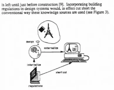
gonzed three types of design; inventive. innovative, and routlne. Smce most design tasksarerepresentative of the latter category much of the work presented in this paperwill apply to rouone deSIgn. A definition of design was proposed by Koegel [12]:is left until juSt before consU11ction [9]. Incorporating building regulations in design systems would. in effect cut shon the conventional way these knowledge sourcesareused (see Figure3).
,.,,,ffJ
o externelizereference models are implicit within the regulations and are scpar:lte from the constraints imposed byaspecific regulation such as the National Building Code of Canada.
There appear to be several different models within a specific
regulation, each forming part of a hierarchy. One such hierarchy, for the National Building Code of Canada (NBCC), is shown in Figure 4. Therearemodels of the major systems within a building (structural, mechanical, elecoical, and plumbing systems for example) as well as various models of use (e.g.• architectural [occupancyl, andfrre (frrezones and smoke control]) at the lower levels of the hierarchy. The representation of various pans ofa
building varies considerably, two-dimensional models with linear elements for structures versus three-dimensional time-dependent models with three-dimensional elements for smoke movement. Since all these models, in fact,arederived from one physical object, or system of objects. all the models should fit together to form a coherent picture of a building. The top-level referencemodels should have knowledge about the various subcomponent modelsand how they interact.
Figure4. Abuilding reference model contllined within theNalionalBuilding Code ofCanada
INCORPORATING REGULATORY INFORMATION INTO DESIGN SYSTEMS
requlat1on.
Figure 3. IncOfllOration of knowledge in building regulations into a design.
Regulations in the construction industryarepredominantly concerned with life safety and consist of a set of minimum requirements that mt'st be met by a given design. A model regulation defines various components that comprise the objects within the scope of the regulation and supplies a set of technical requirements that mustbe
meet The requirements can be viewed as a set of constraints that apply to the atoibutes of objects defined by the document and the relationships between those objects. The technical requirements that comprise such documents fall into one of two categories:(1)
prescriptive or(2)performance.
An example of a prescriptive requirement is:
Strueturel Mecllenical Modal Model
Plumbinq Electrical Architecturel fira Model Model Modal Hodol
3.1.8.1.(5) Eltcept forclosures,therequiredjire-resisUlllCe ratingof evert
firewallshallbe provided by masonry or concrete [16].
An example of performance requirement is:
13.12.3 Connections in Combined Shear and Tension Boles in
a joint requiTed to develop resistance to both tensionand shear shall be proportionedsothat the following relationship is satisfied for the specified loads:
ZZANNNNKセ\]
1.0 Vs nAbFu whereVs = slip rcsist.allce as defined in Clauses 13.12.2. Except that the factored tension TfShall not exceed T r given in Clause 13.11.3. (5].
MODELS IN REGULATORY DOCllMENTS [CAD systems deal with objects. Theyareobject manipulation systems containing geomeoic modelers and large amounts of related information that comprise a design. One view of regulations is that they consist of an implicit model of the systems or artifacts within the scope of the regulation. This model is basically a collection of objects and the relationships between them. Technical requirements in the regulation constitute a set of constraints imposed on the modeL Constructing a reference model consists of explicitly defining the objects and relationships, referred to in the regulations. Representing the actual regulatory requirements consists of defining and
representing the constraints that apply to this model.
Other research on codes and standards has been concerned with the structure, readability. and consistency of regulations [3].[7],[181.
Work in this area models the static surface structure of the regulatory document. The models contain, among other things, the hierarchy of sections and subsections and relationships between sections. This kind of model of regulations is different from the model described above.
The goal of this work is the development of reference models and incorporation of these models into intelligent CAD svstems. These
A reference model of the objects governed by a regulatory document can be derived from the document itself and from ancillary
information. The purpose of the model is to facilitate the design process. Geometric modelers deal with lines, curves.areas.and volumes. The reference model relates these primitive objectsto
tangible objects such as floors. walls, and mechanical equipment In ordertoincorporate regulatory information within a ICAD system a model must be present. The constraints in codes and standardsare
written for and intended to apply to tangible objects rather than geometric primitives. It is essential that objects or groups of primitives be labeled as walls, for example. before a constraint regarding the composition or location of walls can be imposed or satisfied. Several design systems have regulations incorporated within them [8],(9],[10],[11] [14],[15]. These systems. however have embedded the regulatory knowledge directly into the design system. Our approach is to separate the knowledge in the regulations and the model of what's being designed from the ICAD system or geometric modeler. This is analogous to the separation of domain knowledge from the inference mechanism in knowledge-based systems.
BUILDING A MODEL: AN EXAMPLE
Constructing a reference model from a regulation typically consists of the following steps:
I. Enumerate the objects or concepts in the regulation. 2. Identify the relations between the objects.
3. Graph the objects and relations.
4. Build a model from the objects and relations. 5. Identify and represent the constraints.
Building the Reference Model As stated earlier, a regulation defines objects. relationships between objects, and constraints. The reference model consists of the objects and their relationships. while the constraints are external to the model and represent the technical requirements for a particular regulation.
A Section from -the NBCC An article dealing with ducts for low-capaciry heating systems will serve as an example of how a 14.4.2
[entity] [entity] [entity] [entity] [entity] [entity]
SUPPL Y; supplyis Acr of supplying, a generalization of the GIVE
Acr; triadicrelation
[supply]-(agent) .>
(n:pt) -> (00)) ->
TRANSFORM;theAcr TRANSFORM transformsanentityto
another, triadic relatioo [lI'anSfonnI·
(agent) -> (result) ->
(ob)) .>
SERVES:towork for;tosupply,toprovide. beusedby,tofunction for,tomeet a need orn:quiremenL;X SERVES Y
Havingセョオュ・イ。エ・、 theーッウウゥ「セ・ objects in a model and identifying ,the relanons between .those objects the first stepinthe process of
consrrucnng aュセ・ャ ts the generation of object/relation graphs. The graph. shown m FIgure 5 shows a generalization hierarchy derived by graphing the IS_A relation. Component hierarchies can be generated ,by graphing the PART_OF relation.
Ar!ifocU
,
セセセ
M o c f t 0 f \ t C l l Tr"nl<1nq
EQutplMnt
..----r---...
I
Co/l4ult I'lp. DuctAppll.nee
!"'-.
セ
R,turftsuGpセGQ
セZNLZZ Clreuloti"" fon Duct. Duc1.
Vantiloli"" tleolinq Air-Conclitio/linq AI 01 I ti
I
AO,I1tnce Ap,litnc:a ."U8te.t F.: rcu, nq V.rtitl)
I
セオイョSPICIHe,ttrMJ Ducts
Appll'llCO
ウーッ」ッセNイョ
...HootO'
I
I
fI ropl_ Slow" So; .rUnit Centnl linter furM(.e ... F•• I-rlm furneee ___ Solid FUll fired Furlll<t
PART_OF; relation ofpartStoa compositeObject,aggregation:Xis
PART_OFY
Graphing the Obiects and Relat;ons
NUMBER_OF: indicalCS the numbCioI lhing; X NUMBER_OF Y read as number of Xisy
Building a Model
fイッセ the object relation graphs the model consrruction process can begm. Although there ts no well-defined algorithm for constructing a model, the process can be described as a combination of domain knowledge with background knowledge. Figure 6 shows two models. one for a duet and the other for an appliance. The models
arerepresented using a concepmal graph [17]. Concepmal graphs were chosen because of their concise and clear nature. For example. the conceprual graph representing the duct shown in Figure 6 canbe read.as: A duct is an artifact that serves one or more spaces or appliances. Two or more openings fonn pan of the duct and the openings are located in a space or at an appliance. Ductsaremade of aュ。エ・ョセ and the materialhas a combustibility attribute. A similar descnpnon canbe glven for the the model of an appliance. These ,two examples demonstrate the derivation of partial models from a
regulatory document. They are relatively independent of the ,document tend to be functional in their description. The list of objects after expanding the tenns to one level is:
Relurn ductmeans a duct for conveying air fromaspace being heated.
vcntilated or ::tir-condilioncd backtolhe healing, venti1:lting or::tir· condiLioning appliaJU:e.
retumduct
duet ::Ur
space
heating/ventilating/air conditioning appliallce radiation
furnaceheal exchanger
f = e radiaLin g part f = e space-healing appliance warmaic healing medium duets furnacecasing furnace noncombUSlible a=plaJlcc criteria CAN4-S1l4
ATIR: altribute of an object or conccpt: X is an A1TR of Y
6.2.4.5.(3) Whereanypan of areturn ductwiUbe CJ(posedto
mdialion from thefurnace heatexchanger or olher radiatingpart wilhin
lhefurnaa.such pan of areturn ductdirectly aboveorwithin 600 mm
of lhe outsidefurnacecasingshallbenoncombustible.
LoeATION: indicalCS lhc 10C:llion of an objccl in space; X LOCATION isY
return duJ:t
radiation
furnaceheat exchanger
radiating part
jiunace
furnacecasing
noncombustible
Tne process of tenn expansion continues until each tenn in the list is fully expanded. An expanded list of the potential objects defined by a sample sentence of the Code is given in Cornick [6].
Identifv the Relationships The next step in consrructing a model is the identification of the relationships between the objects in the document. Consider the following possible relationships between objects [17]:
To constrUct a model, all potential objects should be elaborated on until they can no longer be expanded (this is analogous to a LISP macroexpand). The first object selected for expansion in the list is the object return duct. The definition of a return duct is given in the Code:
The list of objects and concepts contained within the sentence is: partial reference model can be consrruCted using the infonnation contained within the NBCC. This article, number 6.2.4.(5) [17] was chosen arbitrarily from the Codeland contains fifteen sentences penaining to ducts.
Bujldjng The Model· Enumerate the Objects The first step in defining a partial building reference model istoenumerate all the objects contained within the article. (Italicized wordsarespectal tenns defined within the scope of the NBCC.) Consider the following sentence:
MATR: material of rclation. indic:'lcS lhal whal the objcct/concept is made of: X is MATR of Y.
Figure5. Partialgeneralization hierarchy derived from Article6.2.4.5.of lhe NBCC.
I Code refers10the Naliorol Building Codc of Canadll
[duct]_ (s.rv.s)_ l(spec.l_ ( o r ) _ {aPllllclltlc.-n
/
(parLof) (numb.r-of) - 1>=il
;
(opening) _ (Iocetlon) _ Ilspecel _ ( o r ) _ {appllcance-II
•
(number_of) - (>-21
(motr)
,
Imato,;al! _ _ (attr> _ [combusttbillty]
Generalization hierarchies are also a form of constraint. Constraints on attributeS or characteristics of objects are generated as
specialization occurs. Figure 8 demonstrates the application of constraints as the specialization from a generic appliance to a space-heater is made. These constraints are applied to the model of the generic appliance shown in Figure 6.
SpllCt-llttti nq .pplhnc. ml.n, .n .pplt.nce;nt.nded fer the ,upplセゥ nq of lleat ;0 • room
ッイLセ 、ゥイ・」エャセL ,uen u a ,poe. h••tlr. firlplecl, or unit heet.r, or IG room. or
'PIC"of. bU1ldlnq throuqh. Ilutinq '\jOtlm .uch ... centrol furhKO or. boilor.
[spllce)
USING THE MODEL AND CONSTRAINTS
Figure8 Specialization of the appliance model expressed as consuaints. The defInitions are from the NBCC.
MM{suppQyiセ
1
(rcpt)(Ot!J)
j
[Jatl lspllce heeterl ---- (ognt)
セ
HpッイセoヲI
[duct!
_ _- - - [specel (locat1on)
[spece-heeting opplloncel- (egnl) - [supplyl ... (rept)
•
t
(obP
セ
[hellt]
Spttt He.;er m..", • ,poc.- ....tinq Ipplt.nct for Ilutinq t...roamor.poet 'oIHhln ...hich ittoI...tod, 'oIithaut the u.. of ducu.
Applt,nc:. mltMaセ・エ to corwert (cal into ant'" aM tnctudal ,II CltftPl"'ftt., ceIlt"1.
,.;rtnq .... ptpl nq re,UlreOtobo p.n of tho dmCl「セ lho .ppIlCllbl. rtollCllrO roforr"toInth,.Code.
[appllence) _ (agnt) - [tronsform)- (reSull) - [.n.rgy) - (oltr)
j
(parLof) _[component]i
"""
(obi>{ウエッャセZMxi
(location) , [cantrallI
I
Iwirel 'f.'f I ) [on.rgy] -(atlr) - !slalt:"yl (spocel pipe
Figure 6. Two models. a model of duct and model of an appliance. as defined by the NBCC.
6.2.4.5.(4) Relurn dUClSserving solid-fuel fll'edfurMces shall be
consuucted of lWncombusrible material.
The technical requirements of a specific regulation
represent
constraints imposed on the objeCts within the scope of document Consider the following two requirements of ducts:
6.2.4.5.(7) Avertical relurn dUCI shall have openingstoretllrn air on not more than I floor.
These requirements constrain the combustibility attribute of dUCts in one case and the configuration of the duct system in the second. If the constraints are represented as relations then conceptual graphs can alsobeused to express constraints on the modeL These constraints are shown in Figure 7. The first constraint can be viewed in two ways. A conventional view is that it constrains an attribute-value slot of the material object, however it could alsobeviewed as a constraint on the type of object a combustible duct may serve. i.e. a solid fuel-fired furnace.
Constraint -, 6.2.4.5.(4)
Return ouct, sorvinq .. lid fuel-fired furnllCn ,h.nbeconstructed of noncombu,11 bt Ie m.teri.1
(return oucU-- (serves)--- (solid fuel-(ireO furnecel
I
,
(motr)I
,
[meteriol] ( o t t r ) - [noncombustibleIModels and constraints derived from regulatory documents can be used in two ways. Firstly, a model could be used to establish design expectations. If some object in a design were created or a labeled as a duct the design system would generate a set of expectations about openings. spaces. appliances. and materials for example. These expectations would have to be met in order to complete the design. A second use is for the verification of designs. Verification could occur either during the design process or during a post-design phase. Using a model for interactive verification is similar to the
establishment of design expectations. As the design becomes refined, expectations change and regulatory constraints and be brought to bear. For example.ifduring a design an item is labeled
0-duct then a space or appliance would 'be expected because of the serve relation. If that expectation slot were filled with a solid fuel-fired furnace then the combustibility attribute of the duct material wouldbeconstrained to be noncombustible. A combustible material would not be allow to fulfill that expectation. In post-design verification a given design canbematched against the model to insure completeness and then against applicable constraints to ensure compliance.
CONCLUSIONS
Con,tr.int-2 6.2.4.5.(7)
Averic.1 return duct 'hell ha"e openinq, to return .ir on not more th.n I floor
[verticol return duct! _ _ (serves) _ _ [floor oreel
Lーッ」セッイI
/GLBュLセL⦅ッョセ
",
I[return-oJr _ _ Oocetion) openingsl
1
(number_of) - -[>= II
To enable designers to design effectively using computers. knowledge about regulations must be included in CAD systems. Models of artifacts. such as buildings. are encoded implicitly into regulations and. therefore. a considerable amount of work needs to be carried out on the representation of these regulations. In orderto
incorporate regulations into CAD systems. one or several reference models implicit in regulations mustbeexplicated in order to couple nongeometric information with geometric modelers. Linking the geometric objects of a CAD system to the objects of a building reference model would embody the objects with technical and administrative knowledge required for intelligent design. A flexible approach involves separation of the reference model. that is. objects and the relationships between objects, from the technical
requirements or constraints prescribed by the regulation.
Figure 7. The represenmtion of requirements 6.2.4.5.(4) and (7) as constraints.
REFERENCES
[l)F.Arbab, "A paradigm for intelligent CAD." In:P.Hagen and T. Tomiyama (eds.) Inteiliient CAP systems I: Theorencal and methodolQgical aspects Berlin: Springer-Verlag pp. 20-39. 1987 [2] B-C. Bjork. "Ratas -aproposed Finnish building prcxiuct
model." Acta Polytechnica Scandinavica: Civil Engineering and Building ConsIDIction Series (92), pp. 97 -106. 1989
[3] J.M. Blackmore, "The development of the building code of Australia, The project management of
a
complex code." In:セ・・、ゥョァウ of the International Conference onmオョゥ」ゥーセ Code AdminisqationJ3ui1ding Safety and the Computer Winrnpeg, Manitoba, Canada, 24-28 September 1989, Manitoba Building Officials Associations Inc pp. 27-42.
[4]D.C. Brown and B. Chandrasekaran. "Expert systems fora
class of design activity." In: 1. S. Gero(ed) eroceedjnis Qf the
IFIP
WG5,2 WQrkini CQnference on KnQwledge Eniineering in Computer-Aided DesilID, Budapest. Hungary, 17·19 September 1984, Amsterdam: North Holland pp.258-282.[5] CAN3-S 16.1-M78 Steel strYcttlres for buildings - Limit states
セr・ク、。ャ・ Ontario Canada: Canadian Standards Association. 1978
[14] P. D. Mitusch. Expert system.fQr theセッイキ・ァゥ。ョ 「オゥャ、ゥョセ reflUlatiQOS - A new approach, Oslo. Norway: Norwegian Building Research Institute, P.O. Box H 123, Blindhem N-0314 Oslo. Norway. 1988
[15] W. B. Mugridge. and 1.
G.
Hosking, (1988) "The development of anExpert
System for wall bracing design." Reprint No. 73U2m.
Reprintedfrom Proceedings of the Third New Zealand Conference on Expert Systems. 11-13 May, 1988. Wellington N.Z. Porirua, New Zealand: Building Research Association of New Zealand. Moonshine Road, J udgeford Postal Address -Private Bag, Porirua, New Zealand. 1988[16] NBCC. The NatiQnalbyゥャ、ゥョセ Code; ofc。ョ。、セ (9th ed,).
Ottawa
Ontario Canada:Issued by the Associate Committee on the National BuildingCode,
National Research Councilof Canada. 1985.[171J.F. Sowa,cqョ」セーエオ。A Structures: InformariQn Processing in Mind
and
Machine,Don Mills.Ontario, Addison-Wesley, 1984 [18]D.
J. Vanier. "Computerization of Building Regulations." In: Proceedings of the International CQnt:erence on Municipal CQde AdministratiQn Building SafetY and the Computer, Winnipeg Manitoba Canada. 24-28 September, Manitoba Building Officials Associations Inc pp. 43-62. 1989.(6] S. M. Cornick. D. A. Leishman. and J. R. Thomas.
"Incorporating Building Regulations into Design Systems: An Object Oriented Approach." ASHBAE TransactiQns, Vol. 96, Pt. 2, 1990.
[7] S. M. Cornick. "HyperCode: The building code as a
hyper<iocument." Submitted to Engineering with Computers: An InteroatiQnal Journal for Computer-Aided Mechanical and Structural Engineering, 1990.
[8] A.H. Dechapunya, and R. S. Whimey "Knowledge-based systems for building technology in New Zealand." Reprint No. 83 (988). Reprinted from the Proceedings of Symposium on Knowledge-based Systems in Civil Engineering, August 1988, Monash University, Clayton. Porirua. New Zealand: Building Research Association of New Zealand, Moonshine Road. Judgeford Postal Address - Private Bag, Porirua, New Zealand. 1988.
[9] C.L.Dym. R. P. Henchy, E. A. Felis. and S. Gonick, "A knowledge-based system for automated arehitecrural code checking." Computer-Aided Design. Vol. 20 No.3 April 1990. pp. 137-145.
[10] J. G. Hosking, S. Lomas. W. B. Mugridge, and A.J: .
Cranston. "The development of an expert system forselSIlllC loading." Reprint NQ. 84(988). Reprinted from the . Proceedings of Symposium on Knowledge-based Systems10
CivilEngineering, August 1988. Monash Umverslty, Clayton. Porirua, New Zealand: Building Research Association of New Zealand. Moonshine Road. Judgeford Postal Address - Private Bag, Porirua. New Zealand. 1988
[11] J.G.Hosking, W. B. Mugridge. and M. Buis "Expert systems for regulations and codes." Reprint No.66(1987), Reprinted from Proceedings of the Second New Zealand Conference on Expert Systems,2-4February 1987 Auckland N.Z. Porirua. New Zealand: Building Research Association of New Zealand, Moonshine Road. Judgeford Postal Address - Private Bag, Porirua. New Zealand 1987..
[12]J.F. Koegel, "A Theoretical model for intelligent CAD." In: P. Hagen and T. Tomiyama (eds). Intelligent Cft.D SystemsI:
Theoretical and methodologJcaJ aspects, Berlin: Sprmger- Verlag pp. 206-223. 1987
[13J J. Lundequist. and Kjelldahl.L."Models in computer-aided . . architecrural design work." Acta PQlytechmca ScandinavlCa: Civ11 Engineering and Building Conscruction Series (92), pp. 19-25, 1989.
![Figure 1. A functional view of a mechanical CAD sySlClll [12].](https://thumb-eu.123doks.com/thumbv2/123doknet/14265067.489725/2.912.64.889.47.1147/figure-functional-view-mechanical-cad-syslclll.webp)