HAL Id: tel-00609347
https://tel.archives-ouvertes.fr/tel-00609347
Submitted on 18 Jul 2011HAL is a multi-disciplinary open access archive for the deposit and dissemination of sci-entific research documents, whether they are pub-lished or not. The documents may come from teaching and research institutions in France or
L’archive ouverte pluridisciplinaire HAL, est destinée au dépôt et à la diffusion de documents scientifiques de niveau recherche, publiés ou non, émanant des établissements d’enseignement et de recherche français ou étrangers, des laboratoires
Experimental Investigation on the Morphology of
Interstellar Ice Analogues
Mario Accolla
To cite this version:
Mario Accolla. Experimental Investigation on the Morphology of Interstellar Ice Analogues. Astro-physics [astro-ph]. Université de Cergy Pontoise, 2010. English. �tel-00609347�
If I have seen further,
it is by standing on
the shoulders of Giants
(Sir Isaac Newton)
Questo lavoro è dedicato alla mia piccola figlioletta,
e alla sua contagiosa voglia di vivere
Preface
Laboratory astrophysics is one of the youngest branches of Astrophysics. Specifically, it denotes the investigation of solid or gas phases in the different astrophysical environments by laboratory simulation experiments. Actually, prosperous developments in astrophysics would have been impossible with-out a strong laboratory background. So, for example, it was the case of spectroscopy: the interpretation of extraterrestrial absorption and emission spectra of dust, molecules, ions and radicals would have been impossible without the comparison with the laboratory ones.
Moreover, laboratory studies have allowed and allow the comprehension of many chemical and physical phenomena in the interstellar medium, as the origin and the evolution of some molecules. To date, around 150 molecular species have been tentatively or definitively identified in interstellar or cir-cumstellar clouds1. However, the problem of their formation still remains in many case an open question. For instance, many papers have been dedicated to the problem of molecular hydrogen formation both through laboratory simulations (Duley & Williams, 1984; Pirronello et al., 1997; Manicó et al., 2001) and through numerical simulations (Katz et al., 1999; Cazaux & Tie-lens, 2004; Perets et al., 2005). Actually, H2 is the most abundant molecule
in the Universe, and it has been observed in a wide variety of galactic and extragalactic environments, such as diffuse or molecular clouds, PDRs, plan-etary nebulae, supernova remnants, AGN, etc. Although many steps forward
1You can find a list of the interstellar and circumstellar molecules continuously updated in the following web-site: http://www.astro.uni-koeln.de/cdms/molecules
have been taken, at the moment the problem of the H2 formation is only
par-tially understood. Anyway, it has been recognized that gas phase chemistry alone is not efficient enough to explain its observed high abundances. So, as long ago as 1963, Gould & Salpeter began to consider the possible interplay between gas and dust grains. Actually, grain surface chemistry is now rec-ognized as the most efficient route to form H2 and other simple molecules in
environments where the ionization degree is low.
For this reason, chemical models and experiments have been aimed at de-scribing the complicated chemistry that occurs on grain surfaces. So, an important part of the laboratory astrophysics (sometimes known as Astro-chemistry) is dealing with the kinetics of grain surface reactions in astro-physical conditions. Astrochemistry, describing the different pathways by which the molecules are formed and destroyed, is today a firmly established subject (Fraser et al., 2002). Although the extreme astrophysical environ-ments are reproduced into a laboratory in a quite simplified manner, this kind of experiments try to reproduce in the conditions encountered in inter-stellar clouds in the short span of a few hours the chemical-physical reactions occurring there in thousands of years.
I spent about half of my Italian doctorate in the astrophysical laboratory in Cergy - Pontoise University (France), where I carried out all the experi-ments discussed in this thesis. The impressive experimental set-up housed in this laboratory (called FORMOLISM, i.e. FORmation of MOLecules in the ISM) has been developed with the purpose of studying the interaction of atoms and molecules and the chemical reactions among them on surfaces that simulate those of dust grains under interstellar conditions. Specifically, the surface chemistry investigated by FORMOLISM regards the interaction between gas and interstellar ice analogues. Indeed, laboratory simulations on icy samples allow us to understand why there is a great difference between gas and solid composition. It is known, in fact, that in dense molecular clouds, ices are irradiated by a weak flux of UV photons and by cosmic rays, that are able to break the chemical bonds of the species there present, and the fragments so created are able to recombine producing new chemical species that were not present within the ice. In the astrophysical laboratory, it is possible to simulate the effects induced by photons and energetic ions on the composition and morphology of the ices.
As it will be described in Chapter 1, in interstellar dark clouds dust grains
are covered with icy mantles, mainly constituted by amorphous solid water (ASW). Although the morphology of these ices plays an important role in the interstellar chemistry, to date we have poor knowledge about their in-ternal structure. Within this picture, it lies the heart of the present thesis. In fact, the first set of experiments has been developed to study the gradual compaction of an highly porous ice following the atomic hydrogen exposure. The second set of experiments shows that the solid water formed through the hydrogenation of solid O2 under ultrahigh vacuum conditions is amorphous
with a rather compact (or non-porous) structure.
This thesis is organized as follows:
Chapter 1: The subject of this chapter is the interstellar medium (ISM). In particular, it has been dealt with the gas and the solid phase and their mutual interaction in the ISM, the different kinds of clouds and their chem-ical and physchem-ical characteristics. The aim of this chapter is to emphasize the astrophysical framework of the experiments performed, described and discussed in the Chapters 4 and 5.
Chapter 2: A quite detailed description of the different parts that form the set-up FORMOLISM (the laboratory equipment in Cergy-Pontoise Uni-versity) is given in this chapter.
Chapter 3 : This chapter describes the experimental procedures used to carry out the experiments. Therefore, it is described the different methods of water ice growing used in our set-up, the TPD technique (by stressing its use as probe of ice morphology) and eventually the methods that allow to calibrate the flux of each experimental beam.
Chapter 4 : The present chapter deals with the description and the analysis of the experimental result that emphasize the gradual compaction of an highly porous interstellar ice analogues as consequence of the atomic hydrogen exposure.
Chapter 5 : The experiments discussed in this chapter study a water formation mechanism due to the hydrogenation of molecular oxygen. This
water formation pathway seems to be very efficient in the interstellar condi-tions. Moreover, the water produced through this route is amorphous and with a compact structure.
Contents
1 Astrophysical Framework: the Interstellar Medium 1
1.1 The Milk Way . . . 2
1.2 The interstellar medium . . . 4
1.2.1 The interstellar gas . . . 6
1.2.2 The interstellar dust . . . 8
1.2.3 Interstellar ices . . . 11
1.3 Interstellar clouds . . . 16
1.4 The lifecycle of the Galaxy . . . 21
2 The experimental apparatus: FORMOLISM 23 2.1 Overview of experimental apparatus . . . 24
2.2 The main chamber . . . 24
2.2.1 Baking procedure . . . 26
2.3 The sample holder . . . 28
2.4 The water vapour diffuser . . . 30
2.5 The quadrupole mass spectrometer . . . 30
2.6 Beam lines and microwave cavity . . . 32
3 Experimental procedures 35 3.1 Water ice films on the sample holder . . . 35
3.1.1 Spray deposition . . . 36
3.1.2 Background deposition . . . 37
3.2 TPD technique . . . 39
3.2.1 Theoretical considerations . . . 39
3.2.2 Study of ice morphology through TPD technique . . . 42
3.3 Flux calibration of the beams . . . 46
CONTENTS
3.3.2 Calibration of O2 beam . . . 50
4 Hydrogen exposure of interstellar ice analogues 55 4.1 The experimental method . . . 56
4.2 The experimental results . . . 58
4.3 Analysis of the experimental data: method of direct inversion . . . 60
4.3.1 Description of the method . . . 60
4.3.2 Porosity reduction . . . 63
4.3.3 Discussion . . . 66
4.4 Analysis of the experimental data: Thermal equilibrium model . . . 67
4.5 Origin of the decrease of the porosity . . . 69
4.6 Astrophysical implication . . . 71
4.7 Alternative analysis of the experimental data . . . 73
4.7.1 Theoretical bases of the new model . . . 74
4.7.2 Results obtained with the new model . . . 77
4.7.3 Estimation of molecules formed during the TPD . . . . 86
5 Morphology of just formed water 91 5.1 Models of H2O formation . . . 91
5.2 Previous experiments about H2O formation . . . 92
5.3 The experimental procedure . . . 94
5.3.1 Controlling the D and O2 dose . . . 94
5.4 Experiments on a compact ice substrate . . . 96
5.4.1 H2O formed on a compact ice substrate . . . 99
5.5 Experiments on a porous ice substrate . . . 100
5.5.1 H2O formed on a porous ice substrate . . . 102
Chapter 1
Astrophysical Framework:
the Interstellar Medium
Borrowing a definition of Donald Osterbrock, we can say that the interstel-lar medium is anything not in the stars. Actually, the space among the stars is not empty, but is filled with a tenuous hydrogen and helium gas, and a sprinkling of heavier atoms and molecules, mixed with dust grains.
This matter is not uniformly spread out in space, but it is for the majority concentrated in very large regions, called interstellar clouds (look at the section 1.3). In the Milk Way, the galaxy to which the solar system belongs, clouds are concentrated along the spiral arms, but also occur in the regions between the arms and in the galactic halo, above and below the galactic plane.
In the past, the obscuration due to the interstellar medium was regarded merely as a hindrance to the observation of astronomical objects as stars and galaxies. Therefore, the efforts that astronomers made were simply to find ways of accounting for the extinction of the light of distant objects as accurately as possible, so that the propriety of stars and galaxies might be accurately known. Gradually, however, it became clear that the obscuring medium was interesting in itself. As a matter of fact, for instance, inter-stellar clouds take legitimately part in the cyclic process of inter-stellar evolution.
1.1 The Milk Way
In fact, dense regions inside molecular clouds can be considered proper stel-lar nurseries: their chemical-physical characteristics allow the gravitational collapse of dust and gas, thereby giving life to stellar objects. On the other hand, interstellar material is continuously yielded by stellar winds and super-novae explosions. In this way, the metal contents of the interstellar medium is continuously enriched with heavier elements synthesized during the nucle-osynthesis taking place in the various evolutionary stages of stars.
In the visible part of the electromagnetic spectrum, it is the dust responsible for the interstellar extinction, namely the partial blocking of starlight, that arises from two physical processes, scattering and absorption.
Hence, the ISM is not just detritus of previous generations of stars that blew out matter in the form of dust particles and gas; it is also the site where all the interactions between matter and the different energetic sources (such as cosmic rays, ultraviolet radiation fields, X-rays, shock waves generated by supernovae explosions, gravitational and magnetic fields, etc) take place. For this reason, this astrophysical environment is as much physically and chem-ically complex as crucial to understand the lifecycle of stars in the Galaxy and hence the structure and the dynamics of the galaxy itself.
1.1
The Milk Way
The Milk Way is a spiral galaxy that can be represented as a disc with a spheroidal bulge, and some spiral arms. Fig.1.1.1 shows a schematization of the Milk Way, while Fig.1.1.2 shows what we are able to observe at different wavelengths from our position in the Galaxy.
It was H. Shapley that in the early 1920s determined for the first time the position of the solar system into the Galaxy. In fact, from the observation of Cepheids and RR Lyrae variables1, he found that the majority of the
ob-servable star clusters (called globular clusters) form a spherical distribution. The center of this distribution coincides with the center of the Galaxy and it
1Cepheids and RR Lyrae variables are two particular classes of pulsating variable stars. They present two important characteristics: first of all, it is not hard to know their mean absolute magnitude; then, there is a quite precise relationship between the variable luminosity and the pulsation period. As the difference between absolute and relative magnitude is the distance modulus, the observation of these variable stars provide us two methods of measuring distances, even in other galaxies.
1. ASTROPHYSICAL FRAMEWORK: THE INTERSTELLAR MEDIUM
is about 10 kpc2 far from the Sun. Moreover, the Sun moves in a quasi
cir-cular orbit around the center of the Galaxy, with a rotation period of about 2.3 × 10⁸ years.
According to their abundances of metals, we refer to high metal stars as
Figure 1.1.1: Schematic drawn of our Galaxy, the Milk Way. Top and side view are shown here.
Population I and low metal stars as Population II. Population I stars are
2In Astronomy, the parsec (abbreviated pc) is a basic unit of length.
1 pc is defined as the distance (d) from the Earth to an astronomical object which has a parallax angle (p) of 1 arcsecond.
1.2 The interstellar medium
confined to the galactic plane: they are young enough to have some of their parent cloud around them. On the contrary, Population II stars have no gas and dust around them. They are found in globular clusters and for this reason form a spherical distribution (the so-called halo).
Therefore, the halo consists of the oldest stars known and it is also filled with a very diffuse, hot, highly ionized gas. The spiral arms of our Galaxy contain the interstellar matter, diffuse nebulae, young stars and open clusters emerging from this matter. Because of the difficulties of studying the spiral arms in our Galaxy, much of our understanding of spiral structure comes from comparing our Galaxy to other galaxies. Thus, for instance, it has been observed that spiral arms are sites of ongoing star formation and are brighter than the surrounding disc because of young, hot OB stars that inhabit them. Finally, the visual extinction in the galactic plane makes optical studies of the galactic centre virtually impossible. On the contrary, we are able to ob-serve the galactic centre in the radio and in the infrared parts of spectrum. It is known that the centers of many other galaxies are not simply geomet-rical locations, but they are sites of unusual activity. Even in the Milk Way, some evidences seem to suggest the presence of a central object, that might be a few million M black hole. However, this is an hypothesis, still to be
confirmed.
1.2
The interstellar medium
The interstellar medium (ISM, for short) fills the volume of space among the stars and accounts for 10 - 15% of the total barionic mass of the Galaxy. The gas represents about 99% by mass of the ISM, while the remainder 1% by mass is in the form of dust grains. Usually, gas and dust are well mixed in the clouds: in fact, the 21 cm line emission (due to the spin flip transition in the atomic hydrogen) is strictly related to the optical obscuration due to the presence of dust. Actually, it is the interaction between gas and dust that allows the formation of new molecules or the accretion of dirty ices on the grain surface.
1. ASTROPHYSICAL FRAMEWORK: THE INTERSTELLAR MEDIUM
Figure 1.1.2: Images that show the Milk Way at different wavelenghths (http://adc.astro.umd.edu/mw/ ).
1.2 The interstellar medium
1.2.1
The interstellar gas
The chemical composition of the interstellar matter is close to the so called cosmic composition inferred from element abundances in the Sun. Thus, in-terstellar gas consists mostly of hydrogen (∼ 90% by number) and helium (∼ 10 % by number). Oxygen, carbon and nitrogen comprise about 0.1% by number; all other elements are present only in trace quantities. Because of its higher abundance with respect to the dust, it is the gas that determines the main characteristics of an interstellar cloud. For this reason, as it will be discussed in one of the next sections, interstellar clouds are classified ac-cording to the form in which the hydrogen is found.
Earlier studies of cold interstellar gas utilized optical absorption lines. When the light of an embedded object in the star-forming region or the light from a star passes through a cloud (field star ), some energy is removed at wave-lenghts corresponding to the transitions in the atoms and molecules (see Fig.1.2.1). These studies have allowed the identification of many species (Snow, 1980), some of them result unstable in terrestrial laboratory. How-ever, no hydrogen adsorption line can be observed in this way: in fact, most of the hydrogen is in its ground state because of the low temperature in clouds. Therefore, Lyman lines are the only spectroscopic features of H de-tectable in the far ultraviolet by satellites.
Most of what we know about the interstellar gas comes from radio obser-vations. In the early 1950s, Purcell and his collaborators made the first de-tection of the 21 cm hyperfine structure line from interstellar neutral atomic hydrogen3. At once, the extensive observation of the 21 cm line became a powerful tool for studying the interstellar gas. In fact, as the interstellar dust is transparent at radio wavelengths, radio telescopes are able to detect ob-jects across the Galaxy, far beyond what we can see optically in the presence of dust. However, in this way, it is possible to map only the clouds in which the hydrogen is mostly in the atomic form (the so called HI clouds). About
3Atomic hydrogen in the ground electronic state can produce a radio line at wavelength of 21 cm. This line is due to the hyperfine splitting arising from the spins of the proton and the electron changing from a parallel to an anti-parallel configuration, and vice versa. Indeed, electron and proton spins can be either parallel and anti-parallel. To the state with the spins of the protons and the electron parallel corresponds a higher energy than to the state with spins anti-parallel. The atom can undergo transitions between these two states: their energy difference (of the order of 10−6 eV) corresponds to a frequency of about 1400 M Hz (λ ≈ 21 cm)
1. ASTROPHYSICAL FRAMEWORK: THE INTERSTELLAR MEDIUM
Figure 1.2.1: The interaction between the starlight and the interstellar matter that lies along roughly the same line of sight allows to study the elements that populate the cloud.
the clouds in which the hydrogen is mostly molecular (molecular clouds), other methods have to be used.
Actually, in the Universe, H2 is the most abundant molecule by far, but it is
also the most elusive: in fact it is a homonuclear diatomic molecule, and for this reason it has not permanent electric dipole moment, which means that only quadrupole transitions are allowed by which H2 molecule can radiate.
Thus, cold H2 is invisible for radio or sub-mm observations. As the majority
of the cold H2 remains invisible to direct study, most of our knowledge about
the H2 contents is estimated only indirectly, coming from observations of
other molecules, primarily CO that is the second most abundant molecule in the ISM (10−4 − 10−5 times the hydrogen abundances). Thus, in molecular
clouds, H2 makes its presence felt by forcing the electronic transition J = 1-0
of the carbon monoxide, observed in the millimetric region of spectrum. In fact, when an H2 strikes a CO, H2 can loose kinetic energy, by exciting
col-lisionally CO to a higher roto-vibrational energy state; when CO de-excites radiatively emitting a photon, it carries to the observer the information of the presence of molecular hydrogen, that is most frequent collisional partner
1.2 The interstellar medium
of CO. In rarer cases, H2 can gain kinetic energy de-exciting CO.
The ratio of the abundances of molecular to atomic gas (H2 / H) varies as a
function of position in our Galaxy. Molecular hydrogen is most tightly con-fined to the plane of the Galaxy, with vertical scale height above or below the Galactic midplane of roughly 90 pc. On the contrary, atomic hydrogen can be found in the region from 3 kpc out to the edge of the Galactic disk. In the solar neighbourhood the total mass density of gas is 0.04 M pc−3, of which
atomic hydrogen accounts for approximately 77%, molecules contribute for about 17% and ions add an additional 6%.
The optically obscured regions of ISM are dominated by H2 and are
under-abundant in atomic H, whereas regions irradiated by strong radiation fields are dominated by atomic H. The problem of H2 formation at a rate
com-patible with estimated abundances and the photo-dissociation has been in-vestigated by several authors both from a theoretical point of view (recently Cazaux & Tielens, 2004; Perets & Biham, 2006) and from an experimental one (e.g. Pirronello et al., 1997; Manicó et al., 2001; Hornekær et al., 2003). It has long been recognized that hydrogen recombination (H + H → H2)
occurs with high efficiency on surfaces of interstellar dust grains (that serve as catalyst for this process) under a wide range of physical condition. On the contrary, it is widely accepted that gas phase routes for the conversion of hydrogen atoms to molecules are not rather efficient to account for observed H2 abundances (Hollenbach & Salpeter, 1971).
1.2.2
The interstellar dust
Although dust grains contribute only approximately 1% of the barionic mass in interstellar clouds, they play a crucial part in the interstellar chemistry and in the evolution of clouds. Indeed, dust grains act as catalyst in ISM, allowing the atoms adsorbed on the surface to move along their surface, meet each other and react. The grains also allow the newly formed molecules to lose their energy, and therefore prevent them from redissociating once they are formed (it is the case, for instance, of the molecular hydrogen).
Many evidences confirm the presence of solid small particles in the ISM, with a range of sizes between 1 nm and 3 µm 4. First of all, the so called
4It is possible to estimate grain sizes, studying the variation of the interstellar extinction with the wavelength. So, if the grain size r is much greater than the wavelength λ,
1. ASTROPHYSICAL FRAMEWORK: THE INTERSTELLAR MEDIUM
extinction curve of starlight in the visible and ultraviolet wavelengths, due to the scattering and the absorption of the starlight. The amount of ex-tinction is wavelength-dependent: the shorter the wavelength, the higher the extinction. Thus, red light is not scattered as strongly as blue light. For this reason, starlight, passing through dust clouds, becomes reddened as the blue is removed. This effect, called interstellar reddening, causes stars to appear redder than their effective colour.
Even the weak linear polarization of starlight is a proof of the existence of dust grains in the ISM. This necessarily implies that cannot be spherical, as often assumed in modelling. Grains are elongate particles, modeled as asymmetric spheroids made of paramagnetic material and therefore partially aligned by interstellar magnetic field.
The analyses of the infrared absorption features (for example those acquired by the satellite ISO) indicate that interstellar dust grains are mainly com-posed of silicates or carbonaceous material. The adsorption features observed at 10 µm and 12 µm are due to the vibrational transitions in silicates (SiO and SiO2) and water ice. On the contrary, the interstellar extinction on the
ultraviolet window can be explained by small graphite grains.
Information about the composition of cosmic dust can be worked out also from considerations of the so-called elemental depletions. In fact, while some species, such as N and S, have gas phase abundances (relative to H) which are approximately solar, certain others (such as M g, Al, Si, T i, Ca, F e, N i, Cr) show abundances which are far below solar. Since we presume that the interstellar abundances are approximately solar (Sofia & Meyer, 2001), the atoms missing from the gas must be locked up in dust grain (Snow & Witt, 1996). Therefore, the observed elemental depletions provide a clue to the composition of interstellar dust (Fig.1.2.2). Interstellar dust grains are presumably ejected from hot stars: in fact, the densities in the interstel-lar clouds are too low for the grains to be formed directly where they are
then geometric optics can be applied and the extinction is roughly constant. If r λ, the extinction is very small. If r is comparable to λ, the diffraction effects in the scattering process are important. Hence, the wavelength dependence of the extinction is very important when r ∼= λ. Comparing observation with theoretical calculation, we find that interstellar grain are not all the same size: the visible extinction is due to grains with a typical size of 0.2 µm. The ultraviolet extinction, on the other hands, reflects the presence of grains with sizes in the range 5-20 nm, and the size distribution is believed to follow a power law of the radius with exponent -3.5 (Mathis, 1996).
1.2 The interstellar medium
Figure 1.2.2: Elemental depletion (i.e. the difference: log (abundance measured) - log (abundance cosmic) ) in the molecular cloud ζ Oph is plotted as a function of the condensation temperature of elements. Elements with Tc≥ 1200 K are able
to form "refractory" solid. For instance, look at the depletion of Ca: log D ∼ -4 → 104 times less than solar abundance
1. ASTROPHYSICAL FRAMEWORK: THE INTERSTELLAR MEDIUM
observed. Thus, towards the end of their lives, stars on asymptotic giant branch of the H-R diagram (AGB stars) are known to eject much of their envelope into space. So, these stars are surrounded by rather extended atmo-spheres, that are cool and dense enough to facilitate the nucleation of atoms and molecules, forming small solid particles. Stellar outflows can be carbon reach or oxygen rich: the two types determine the nature of the dust that is produced. Where carbon is more abundant than oxygen, oxygen is almost entirely locked up in carbon monoxide, and the excess carbon produces a rich chemistry of carbon-based molecules and carbonaceous dust. On the other hand, where oxygen in an envelope is more abundant than carbon, the excess of oxygen makes metallic oxide that nucleate to form solid oxide and silicates (Williams & Herbst, 2002).
1.2.3
Interstellar ices
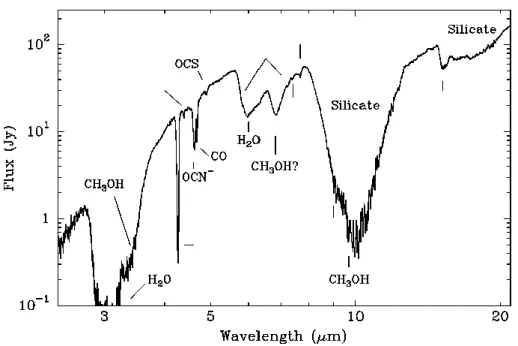
In cold and dense clouds (that are interstellar regions well shielded from the far ultra-violet radiation) spectroscopy studies have shown the existence of ice mantles on the grain surfaces (e.g. Pontoppidan et al., 2004). Interstellar ices are mainly formed of water, unambiguously identified by bending mode of amorphous H2O ice (6.0 µm) and by the O-H stretching mode in H2O ice
(3.1 µm). However, interstellar water ice is mixed with several other species such as CO, CO2, CH3OH, CH4, N H3, OCS, etc (look at Table 1.1 and
Fig. 1.2.3). In part, these molecules freeze out onto the grains from the gas phase; however, mantle composition doesn’t reflect gas phase composition or abundances. For instance, despite numerous searches, CO2 has not yet been
observed in gas phase, while it is widely detected as an ice condensed onto dust surfaces (Boonman et al., 2000).
Hence, new molecules are formed when reactive gaseous species condense on the grain surfaces or when ices are energetically processed by UV radiation and cosmic rays; several laboratory investigations support this interpreta-tion too. Indeed, it is generally accepted that also water ice forms because of surface reactions on grain mantle at low temperature. On the contrary, direct accretion of most complex gas phase species play a very minor role in determining interstellar ice composition.
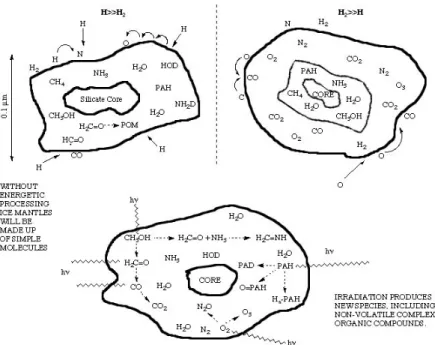
Actually, ice composition in molecular clouds depends on the local condi-tions (Fig.1.3.1); being hydrogen largely the most abundant element in the Universe, overall grain surface chemistry is moderated by the H/H2 ratio.
1.2 The interstellar medium
Figure 1.2.3: This spectrum (Gibb et al., 2000) is an inventory of interstellar ices toward the embedded protostar W33A. It shows the absorption features both due to the dust grains (silicate bands) and due to the "dirty" ice mantles.
1. ASTROPHYSICAL FRAMEWORK: THE INTERSTELLAR MEDIUM
Molecule Abundance(%) Molecule Abundance(%)
H2O 100 CO 3-50 CO2 7-25 N H3 < 10 CH3OH 2-25 CH4 0.9-1.9 H2CO 3-7 OCS 0.1 C2H6 ≤ 0.4 OCN− ≤ 1.9 N H4+ 3-17 HCOOH ≤ 1.7
Table 1.1: Molecules detected in interstellar ices towards protostars. Molecular abundances are relative to the water ice (Van Broekhuizen, PhD thesis)
In regions where this ratio is large, H atom addition dominates and species as H2O, N H3 and CH4 are expected to be prominent. If the H/H2 ratio is
less than 1, reactive species such as O and N are free to interact with one another, forming molecules such as CO, CO2, O2 and N2. Thus, at least two
qualitatively different types of ice mantles are expected to be produced by grain surface reactions, one dominated by polar H-bounded molecules and the other dominates by non-polar (or only slightly polar) highly unsaturated molecules (Tielens et al., 1991). By way of an example, analyzing the profile of solid CO band coming from young stellar objects, it is possible to recog-nize the two kinds of ice mixture (polar and non-polar one) and in addition a third kind, which nature is still uncertain. In fact, CO stretching profile (2140 cm−1) can be thought as superposition of 3 components, each one de-scribing a different icy mixture. Thus, according to the physical condition of each cloud, it can be prevalent one of this component (Pontoppidan et al., 2003).
Even though water is the main constituent in interstellar ice mantles, its chemical origin is not well understood. Some theoretical works (e.g. Tielens
1.2 The interstellar medium
Figure 1.2.4: Schematic representation of the different types of ices mantles and their components. The interstellar ice composition in dark clouds depends on the local condition, as the ratio H2/H or the cosmic ray and the radiation field.
1. ASTROPHYSICAL FRAMEWORK: THE INTERSTELLAR MEDIUM
& Hagen, 1982 ; Cuppen & Herbst, 2007) have suggested three main possible pathways for water formation: hydrogenation of O, O2 and O3. However,
up to the time, the lack of realistic experimental simulations has not allowed to clarify the real contribution of each pathway. In the last years, many steps forward have been taken about this subject. Thus, now it is widely accepted that water molecule formation in the gas phase and the following direct accretion on the grain is not efficient enough to reproduce the ob-served H2O ice abundances (e.g. Ceccarelli et al., 2007). In 2006, some
experiments performed through the set-up FORMOLISM have allowed to study the formation of water molecules by exposing a water ice substrate to D and O atoms and O2 molecules, thus simulating water formation in dense
interstellar clouds (Dulieu et al., in preparation). During these experiments, it has been shown that D2 molecules do not react with O atoms nor with O2
molecules residing on the ASW ice surface. Therefore, the water formation process requires hydrogen in atomic form.
Very recently, the H + O2 pathway has been analysed using IR spectroscopy
in situ, by different groups dealing with Astrochemistry. All the experiments (performed in condition roughly similar to the interstellar one) show that the formation route that converts O2 into H2O via H2O2 is more efficient
than previously assumed by theoretical study (Miyauchi et al., 2008; Ioppolo et al., 2008). Moreover, it has been confirmed that the hydrogenation of the molecular oxygen produces amorphous water, with a compact (or non-porous) structure (Oba et al., 2009).
Interstellar water ice is believed to be mainly amorphous, that is to say without a distinct crystalline structure. This has been shown both observa-tionally (Smith et al., 1989) and theoretically (Kouchi et al., 1994). So, while there is quite a general consensus that interstellar water ice is mainly amor-phous, its morphology still remains poorly known, although this parameter has a great importance for interstellar gas-grain reactions. Indeed, labora-tory simulations have demonstrated that ice porosity influences greatly both the efficiency of H2 formation (Roser et al., 2002) and the energy contents
of H2 as it is released from the grain on the ISM just upon its formation
(Hornekær et al., 2003). Moreover, it has been observed (Ayotte et al., 2001) that a porous ice film is able to adsorb between 20 and 50 times more gas than a compact one.
Identification of ice porosity can be based on weak infrared absorption fea-tures (∼ 2.7 µm) due to the O − H vibration of dangling bonds on the
1.3 Interstellar clouds
pore surface (Rowland et al., 1991). But, according our knowledge, to date there have been no detection of dangling bond adsorptions in the infrared spectra of interstellar ices, perhaps suggesting that they have a compact na-ture (Keane et al., 2001). So, it is possible that, after surface reactions only compact amorphous water ice forms on interstellar grains. Otherwise, in con-formity with the results of several laboratory simulations, interstellar porous ice could be compacted by transient heating or stellar radiation or cosmic rays or by some other process.
The work in the present thesis takes place in this picture. Chapter 4, it is shown experimentally the gradual compaction of the porous interstellar ice analogues following atomic hydrogen exposure; whereas, Chapter 5 empha-sizes that the water ice formed through the pathway D + O2 has a non-porous
structure.
1.3
Interstellar clouds
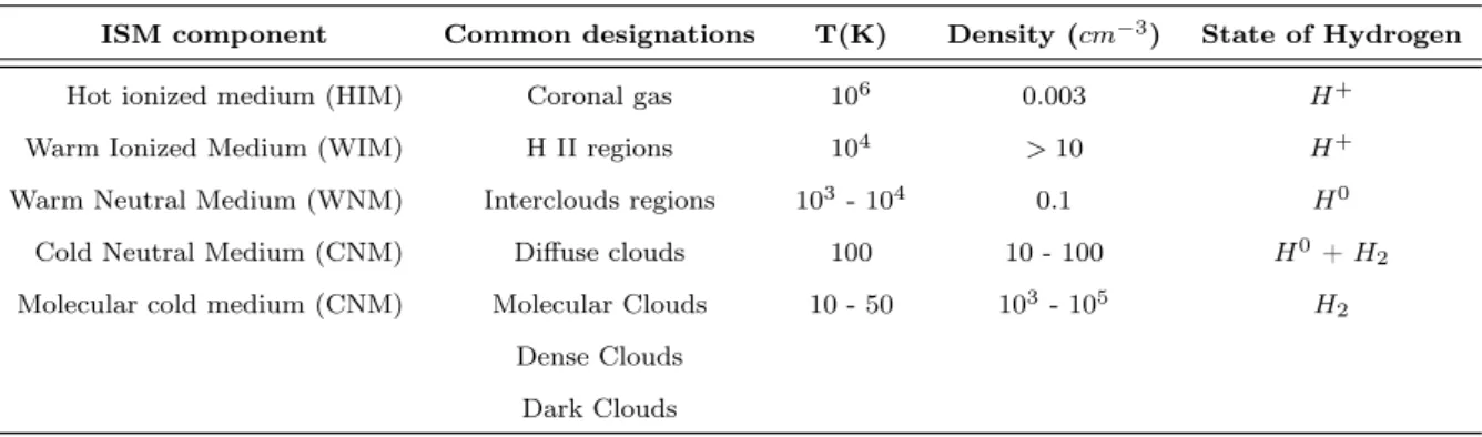
Although it is difficult to classify rigorously the complexity of the interstellar medium, it is possible to identify five broad kinds of interstellar environments according to temperature, phase and density of the hydrogen (see Table 1.2). The physical characteristics of each interstellar cloud depend on the balance between the different heating and cooling mechanisms.
For the subject discussed in the present thesis, denser and cooler interstellar regions are indisputably the more interesting, because only in these regions dust grains are covered by ice. However, for the sake of completeness, a brief description of the other important interstellar environments is given here-after.
A large fraction of the volume of the Milk Way (∼ 50 %) is filled with a tenuous (∼ 10−3 cm−3), ionized and very hot gas (T ∼ 105− 106 K), known
as coronal gas, because comparable to that of the solar corona. This hot gas can be traced through UV absorption lines of highly ionized species (e.g. C IV , S V I, O V I) observed against bright background sources. More-over, such hot plasmas emit continuum (such as bremsstrahlung and radia-tive recombination) and line radiation in the extreme ultraviolet and X-ray wavelenght regions. Supernovae explosions and early type stars generate the
1. ASTROPHYSICAL FRAMEWORK: THE INTERSTELLAR MEDIUM
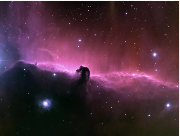
Figure 1.3.1: The Horse Head Nebula is part of Orion molecular cloud. The nebula is formed by the dust blocking the light from the glowing gas in the back-ground. The fuzzy blue patch at lower left of the Horsehead is a reflection nebula, where dust is scattering light from a hidden background star towards us.
1.3 Interstellar clouds
ISM component Common designations T(K) Density (cm−3) State of Hydrogen
Hot ionized medium (HIM) Coronal gas 106 0.003 H+
Warm Ionized Medium (WIM) H II regions 104 > 10 H+
Warm Neutral Medium (WNM) Interclouds regions 103 - 104 0.1 H0
Cold Neutral Medium (CNM) Diffuse clouds 100 10 - 100 H0+ H 2
Molecular cold medium (CNM) Molecular Clouds 10 - 50 103- 105 H 2
Dense Clouds Dark Clouds
Table 1.2: Classification of interstellar clouds. This table is compiled according to the information got in Wooden et al., 2004.
coronal gas when their energetic winds collide with and shock the surround-ing medium. Dust grains in such gas are rapidly destroyed by sputtersurround-ing.
Ionized gas nebulae (or H II regions) are often detected either as bright visible nebulous objects or through optical and UV ionic absorption lines against background sources, or through the emission in the H α recombi-nation line. These regions have a low density (∼ 0.1 cm−3) and relatively high temperatures (∼ 104 K). The source of ionization is not entirely clear.
It seems that these regions are formed by young massive stars with spectral type earlier than B1. These stars emit copious amount of energetic photons (E = hν > 13.6 eV ) able to ionise and heat the surrounding clouds of gas. In H II regions, dust tends to be eroded.
As already discussed, the 21 cm line due to the atomic hydrogen traces the neutral gas of the ISM. This neutral gas can also be observed in optical and UV absorption lines of various element towards bright background stars. The neutral medium is organized in cold (∼ 80 − 100 K) diffuse H I clouds ( CNM, cold neutral medium) and warm (∼ 8000 K) interclouds gas ( WNM, warm neutral medium). A standard H I cloud has a typical density of 50 cm−3 and a size of 10 pc. Interclouds (or WNM) regions have lower density (∼ 0.5 cm−3); they occupy ∼ 30% of the volume of the ISM, and are located
1. ASTROPHYSICAL FRAMEWORK: THE INTERSTELLAR MEDIUM
mainly in photodissociation regions, on the boundaries of HII regions or molecular clouds.
Diffuse clouds are characterized by a low number density; so, UV and visible light from stars can penetrate them and ionise most of the elements, except for the case of hydrogen, which is roughly equally divided into neu-tral atoms and molecules. In these regions, the coexistence of gas and dust is verified: the hydrogen column density shows a correlation with the visual extinction. Furthermore, the high H2 abundance detected in diffuse clouds
concurrently with photo-dissociation entails the presence of an active grain-surface chemistry. The detection of more complex molecules is a further evidence that gas and dust are well mixed.
Molecular clouds are dense enough that they are opaque to starlight. They comprise ∼ 30% of the mass of ISM, but occupy only ∼ 0.05 % of its volume. Although a small but detectable amount of the atomic hydrogen remains (Li & Goldsmith, 2003), the hydrogen is mainly molecular, thereby remaining for the majority invisible to direct study. Therefore, the transition at 2.6 mm due to the carbon monoxide is commonly used as a tracer of molecular gas, even though H2 is always the dominant molecular species, with a H2/CO
ra-tio of 104− 105. In molecular clouds, the material is shielded so well from the
ultraviolet radiation fields than complex molecules can form and dust grains can be covered by thin icy mantles whose composition does not reflect that in the gas phase, thereby stressing a rich grain surface chemistry. In fact, to date more than 150 different molecular species have been detected (mainly through their rotational transitions in the submillimeter wavelength regions) in the shielded environments of molecular clouds. A list of the molecules detected till now is shown in Fig.1.3.2. It is widely recognized the role of the molecules as crucial in the thermal balance of gas in astrophysical objects. In fact, in the Universe, molecules act as natural temperature regulators. They can cool gas to low temperatures and, thereby, allow gravity to overcome thermal forces and clouds to collapse to form new stars and planets. Because of its predominance, molecular hydrogen is turned out to be the most im-portant coolant: this molecule is, in fact, able to extract kinetic energy from the gas and lose it via radiative emission. For the mentioned reasons, in a friendly way, molecular clouds are also called stellar nurseries.
1.3 Interstellar clouds
Figure 1.3.2: List of the interstellar and circumstellar molecules observed until the beginning of 2009. In red are molecules that have been detected by their ro-vibration spectrum, (*) denotes those that have been detected by electronic spectroscopy and (?) denotes tentative detections that have a reasonable chance to
1. ASTROPHYSICAL FRAMEWORK: THE INTERSTELLAR MEDIUM
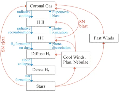
Figure 1.3.3: Scheme of life cycle of the interstellar clouds.
1.4
The lifecycle of the Galaxy
There is a complex link between star formation and the interstellar medium. The interaction between stars and ISM determines the structure, composi-tion, chemical evolution and observational characteristics of the interstellar medium in the Milk Way.
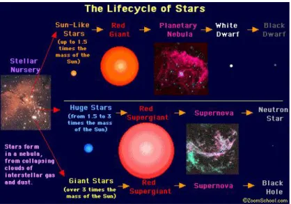
The cold clouds characterized by molecular hydrogen are the birthplace of new stars when they become gravitationally unstable and collapse. Depend-ing on the mass, the formation of the star can follow different routes pro-ducing: Sun-like mass, high-mass or giant-mass star (Fig. 1.4.1). For every routes, each step of the star formation process is characterised by different chemical species, which can be the "signatures" of each of these steps.
All the stars, ejecting gas and dust into the ISM through their wind, influ-ence the interstellar chemistry and thereby the star formation rate. Actually, winds from low-mass stars control the total mass balance of interstellar gas and contribute substantially to the injection of dust and polycyclic aromatic
1.4 The lifecycle of the Galaxy
Figure 1.4.1: According to the initial mass of the collapsing object, star’s evo-lution can follow three different routes.
hydrocarbon molecules (PAHs), that are important heating agents in the in-terstellar gas because likely act as electron donors in the photoelectric effect induced by UV absorption. On the other side, massive stars regulate the ultra-violet photon energy budget and the cosmic-ray flux, which are impor-tant heating, ionization and dissociation sources of the interstellar gas. They are also the source of intermediate-mass elements that play an important role in the interstellar dust.
Because of all these interactions, it is worth stressing that the complexity of the ISM is also due to the fact that this environment is far from being in thermodynamic equilibrium. In fact, in thermodynamic equilibrium, matter is characterized by a single temperature, which describes the velocity dis-tribution, excitation, ionization and molecular composition of the gas. The velocity distribution of the interstellar gas can generally be well described by a single temperature, but excitation, ionization and molecular composi-tion are often very different from thermodynamic equilibrium values at this temperature.
Chapter 2
The experimental apparatus:
FORMOLISM
All the experiments described in this thesis are performed in the astrophys-ical laboratory in Cergy-Pointoise University (France). The apparatus is called FORMOLISM, i.e. FORmation of MOLecules in the ISM, and it is dedicated for investigation of physical-chemical reactions on surfaces of astrophysical interest, in condition roughly similar to the interstellar one, namely low temperature and low density.
I spent about half of my Italian doctorate in that university. Thanks to the availability, the patience and the competence of the scientific team of FORMOLISM, in a short time I became self-confident with the complex experimental device. Actually, I was personally able to carry out all the ex-periments that will be reported in next chapters.
The present chapter describes in detail the laboratory equipment, focusing in particular on the experimental devices used during my experiments.
2.1 Overview of experimental apparatus
2.1
Overview of experimental apparatus
A schematic drawing of FORMOLISM (the experimental equipment in Cergy-Pointoise University) is shown in the Fig.2.1.1. Following the numbers in the figure, the apparatus consists of:
1. An ultra high vacuum (UHV) chamber, i.e. the main chamber; 2. A quadrupole mass spectrometer (QMS);
3. A sample holder connected to a cryostat;
4. Two triple differentially pumped atomic/molecular beam lines.
Each part will be described in detail in the next sections.
2.2
The main chamber
The main chamber consists of a stainless steel cylinder, with radius equal to 15 cm and height equal to 120 cm. So, its volume is ∼ 85 litres, and it is mainly evacuated by a turbo molecular pump (with pumping speed ∼ 1000 l/s), but also by an ion pump and a titanium sublimation pump. In this way, the residual pressure inside the chamber (mainly due to molecular hydrogen and water vapour) can reach values lower than 10−10 mbar, corresponding to a molecular/atomic density of 2 × 106 cm−3. Actually, this density is
still rather high compared to the interstellar one: in a dark cloud, density is estimated to be ∼ 104cm−3 (Williams & Herbst, 2002). However, to date it is
technically impossible to get better vacuum in terrestrial laboratories. There is, in fact, a continuous desorption of species (H2 and H2O, mainly) coming
from the different portions of the apparatus, especially from the walls of the vacuum chamber. In order to minimize this effect, the chamber is periodically warmed up to 100◦C for a few days (baking procedure). In this way, the rate of degassing is drastically cut down when the room temperature is established again into the chamber. Further details about this baking procedure can be found in next Section.
Anyway, residual pressures into the main chamber are low enough to make not very important the pollution level on the surface of the solid sample: indeed, it is easy to evaluate that, at a pressure of 10−10 mbar and a surface
2. THE EXPERIMENTAL APPARATUS: FORMOLISM
Figure 2.1.1: Scheme of FORMOLISM (top view), the laboratory equipment dedicated to the study of solid state for Astrophysics, in Cergy-Pontoise University.
2.2 The main chamber
temperature of 10 K, the sample-holder is coated with ∼1 ML of water vapour only after ∼ 5000 minutes.
Althoug not shown in Fig.2.1.1, the chamber houses a leak valve equipped with a microchannel doser. Once the leak valve is opened, water vapour dif-fuses into the chamber via a micro capillary array. The controlled dosing of the water vapour allows to grow interstellar ice analogues on the previously cooled surface. Two different experimental methods are used depending on the kind of ice we want to grow. Both methods will be carefully described in Section 3.1.
In the experiments discussed in this thesis, the porous ice films (few lay-ers of H2O as thickness) are grown on the top of a quite thick (∼100 ML)
compact ice layer. In this way, our samples are completely isolated from the Cu sample-holder surface, avoiding, thus, complication in the TPD spec-tra arising from the interaction of the gas with the underlying hydrophilic substrate.
2.2.1
Baking procedure
A continuous desorption of species (H2 and H2O, especially) coming from
the walls of the chamber affects the quality of the vacuum into the chamber. Of course, this desorption is compensated by continuous pumping; the com-bination of desorption and pumping gives the limiting pressure value. The rate of degassing from the walls can be drastically cut down through the so called baking procedure. This operation is performed whenever the residual pressure in the chamber at room temperature is higher than 10−9 mbar, for example after each opening of the experimental set-up.
Actually, the baking procedure consists on heating up to ∼100◦C the main chamber for few days. In this way, the rate of desorption is temporarily in-creased and a large amount of the adsorbed species is removed from the walls of the chamber. Thus, when cooling down back to room temperature, the rate of degassing is cut down, and consequently the base pressure is lowered.
During my long stay in the research team of FORMOLISM, we were obliged to open the apparatus many times because of the failures in the mass spec-trometer and the appearance of micrometric leaks in the chamber. For this reason, baking procedure was repeated many times.
electric-2. THE EXPERIMENTAL APPARATUS: FORMOLISM
heating wires and then covered with isolating aluminium foils that help to maintain and homogenize the temperature of the walls. A homemade Lab-view procedure drives the heating phase, allowing the regulation and the control of the heating rate; in this way, the most fragile parts of the set-up (like the windows) are safeguarded from excessive heating.
Figure 2.2.1: Residual gases detected by the mass spectrometer in the UHV chamber before (red) and after (black) a baking procedure. The different species are normalised respect to water vapor (100%) detected before the baking.
Fig.2.2.1 illustrates the importance of the baking procedure, showing the different abundances of the various species forming the residual gas in the main chamber before and after the baking. In the figure, signals detected by the QMS for every mass have been normalized to that of H2O detected
before heating of the set-up. After baking, nitrogen has almost completely disappeared, while the amount of water vapour is reduced by a factor of 100.
2.3 The sample holder
2.3
The sample holder
The sample holder consists of an high conductivity copper circular cylinder, with radius equal to 5 mm. It lies in the main chamber, at the same height of the beam lines, and is connected with the so-called "800 K interface". A very thin silver foil insures a good thermal conductivity between these two elements. Finally, the "800 K interface" is mounted on the second stage of the cryocooler (Fig.2.3.1).
The "800 K interface" (sold by ARSCRYO ) contains an internal thermal switch which protects the cold end of the cryostat from excessive and poten-tially harmful heat while experiments are carried out at elevated tempera-tures. In particular, the switch is automatically open when the temperature of the sample holder becomes higher than 350 K: in this way, the heat trans-fer to the coldest end of the cryostat results unimportant. Moreover, "800 K interface" having an electric resistance, is able to heat the sample holder until 800 K. Therefore, our sample holder can withstand a range of potential temperatures between 8 and 800 K.
The cryostat connected to the "800 K interface" is a two stage cryocooler that operates on the principle of the Gifford-McMahon refrigerator cycle 1.
Although the temperature at the bottom of the second stage is 4.2 K, the lowest temperatures reached by the sample are never lower than 8 K because of the natural thermic losses.
The whole set is mounted on a translation plate, that allows us to move back and forth the sample holder with respect to the centre of the chamber in order to allow a better positioning of the QMS or the water vaporizer.
As shown in Fig.2.3.1, a thermic buckler - made of a mixture of copper and nickel - is screwed at the base of cryostat. It protects and isolates the sample holder, the "800 K interface" and the second stage of the cryostat from IR radiation (the thermal one) coming largely from the wall of the chamber. In this way, it is possible to keep rather stable the temperature of
1Although out of the aims of this thesis, it is worth spending some words about the Gifford-McMahon cycle. Actually, Gifford-McMahon (GM, briefly) refrigerators are the largest application of cryocoolers. A GM cooler is a variation of a Stirling one, because the physical principle is the same. Helium is used as working fluid because of its ideal gas properties and its high thermal conductivity. In practice, the coordinated motion of a piston and a displacer allows the realization of the GM cycle: the thermal cycle consists in a (quasi) isothermal compression and in a (quasi) isothermal expansion of the He gas, besides two isometric transformation.
2. THE EXPERIMENTAL APPARATUS: FORMOLISM
the sample holder, minimizing the heating effect due to the IR irradiation. Fig.2.3.1 shows also the position of the three different types of sensors that measure the temperature. Thus, there is a KP-type thermocouple (Au-F e/Chromel), a K-type thermocouple (Nickel-Chromium/Nickel-aluminium) and a Silicone diode.
The thermometers and the electric resistance in "800 K interface" are con-nected to a controller (Lakeshore 340 ), that allows the reading of the different temperatures and the regulation of the sample temperature, just by varing the power of the heating resistance.
A homemade software code (using Labview ) enables us to check and con-trol the sample temperature by a computer. That is very important because Labview is able to control accurately the heating power setting in order to get a linear increase of the sample temperature during a TPD experiment. Moreover Labview allows also to monitor and to record the trend of the differ-ent temperatures measured by every thermometer as function of the elapsed time.
Figure 2.3.1: Scheme of the cryostat, with longitudinal section of the farthest part.
2.4 The water vapour diffuser
2.4
The water vapour diffuser
The water diffuser in the main chamber can be easily moved and placed in two main positions (in front of or above the sample holder) depending on the kind of water ice we would like to grow (see Paragraph 3.1 for further details).
A small glass vial (∼ 100 cm3) containing liquid water 2 is connected with the UHV chamber via a low rate leak valve. The small vial is also connected to a turbo pump and a pressure gauge. In this way, we are able to read and to controll the saturating water vapour pressure behind the leak valve, before its opening. Generally its value is fixed ∼ 20 mbar.
Once the leak valve is opened, water vapour diffuses into the chamber via a micro capillary array diffuser at the end of ∼ 30 cm stainless steel tube: this rather long pipeline ensures the uniformity of water vapour flux. The micro-capillary system presents a round surface (∼ 1 cm in diameter) composed of hundred channels with an aperture of ∼ 45◦.
2.5
The quadrupole mass spectrometer
A movable quadrupole mass spectrometer (QMS) is mounted in the upper part of the main chamber: at the moment, it represents the main analysis instrument in this laboratory 3.
The QMS (an HIDEN model ) is able to analyze the composition and the abundances of the residual gas into the main chamber or to characterize the atomic/molecular jet coming from the beam lines or to check the desorbed species from the sample during a TPD experiment.
The QMS can be translated vertically and rotated. In the upper position, it serves to analyse the gases present in the chamber, while in the lower position it can either face one of the beams to characterize them and to measure the dissociation rate or face the sample surface to measure the desorption rate.
Fig.2.5.1 shows schematically the main parts that form a QMS. The
in-2When it is necessary to fill the vial, the demineralised water undergoes a purification process. It consists in a series of solidification - fusion cycles: in this way, all the gaseous impurities dissolved in the water are released in the gas phase and can be pumped out.
3FORMOLISM will be soon enriched with an infrared spectrometer able to analyse the icy sample in situ
2. THE EXPERIMENTAL APPARATUS: FORMOLISM
Figure 2.5.1: Schematic description of a quadrupole mass spectrometer (QMS).
strument can be divided into three parts: the ionization zone, the ion flight zone and the ion detector. So, atoms/molecules, entering the quadrupole probe, are ionized via electron bombardment by passing near to a heated tungsten filament and are subsequently accelerated towards the four straight and parallel rods (the ion flight zone). These four metallic rods represent the ion mass filter able to select species according to their mass-to charge ratio (m/z); in fact, a voltage combination of a direct and a radio frequency component is applied between adjacent and opposite rods. Once inside the quadrupole, only ions of a certain m/z will reach the detector, guided by the resonance with the oscillating voltage. The other ions will be expelled from the ion flight zone. Varying the direct and the radio frequency component, the QMS is able to scan all the ions up to a chose mass to charge ratio tech-nically fixed (in our case 50 m/z).
The ion detector is a Channeltron, that is an electron multiplier able to induce a cascade of secondary electrons for each ion impact. The output current so generated in the Channeltron is converted into a digital signal. The digitalized signal is then controlled by a software provided by HIDEN. It allows to monitor and record the acquired information, but also to ad-just the electronic setting of the QMS and the dwelling times between two measurement. Moreover, it is possible to record simultaneously the sample temperature measured by Lakeshore controller during TPD experiments. Our detector must work with residual pressures lower than 10−6 mbar, and it is able to detect partial pressures up to 10−14 mbar.
2.6 Beam lines and microwave cavity
2.6
Beam lines and microwave cavity
FORMOLISM uses the same architecture devised by Pirronello et al. (1997), i.e. it is equipped with two triple differentially pumped atomic/molecular beam lines that are connected with the main chamber and aimed at the sur-face of the sample holder (Fig.2.6.1). In this way, it is possible to expose the sample to two different species simultaneously (e.g. D/D2 and O/O2). Each
Figure 2.6.1: Photo of the three diffentially pumped beam line in FORMOLISM. As here shown, a plasma of deuterium can be created in the tube, behind the first stage.
beam line is composed of three differentially pumped stages: thus a rather low and well-collimated flux of particles can be created in the direction of the sample. The rationale is to select in the gas phase only particles with a precise trajectory, thereby enabling them to reach the sample surface with a very small solid angle (∼ 8 × 10⁻⁶ str). In fact, the gas beam, prior to reach the UHV chamber, must pass in the three stages (i.e. chambers pumped
2. THE EXPERIMENTAL APPARATUS: FORMOLISM
separately) shown in Fig.2.6.1: three aligned (millimetric) diaphragms con-nect each stage with its adjacent. During this three steps, the gas pressure decreases gradually from 1 mbar (in the initial tube) to 10−10 mbar (in the main chamber).
In practice, the gas (molecular hydrogen, for example) is introduced into the first stage of the beam line, with a pressure of 1 mbar as order of magnitude. Through a first tiny diaphragm, a small quantity of the gas passes into the second stage, where there is a lower residual pressure. Here, a second tiny diaphragm (aligned with the previous and the next one) connects to the third stage, where there is a residual pressure of ∼ 10−8 mbar. Between the second and the third stage there is a valve, because last stage is directly connected with the main chamber by the third diaphragm.
A small revolvable metallic plate (called "beam flag") is placed between the third stage and the main chamber. When this flag is closed, the jet of par-ticles reaches directly the sample surface. On the contrary, when the flag is open, the jet is broken and its particles do not arrive straight to the icy sam-ple, but they fill the main chamber: in this case, the particles will condense on the icy sample by "background" deposition.
The methods used to estimate the atomic/molecular flux will be described in the next Chapter. Anyway, its estimation is ∼ 1012 - 1013 cm−2s−1, namely several order of magnitude higher than the interstellar ones. Therefore, mod-els are often necessary in order to extrapolate from laboratory data informa-tion useful for astrophysics.
The first stage of each beam line houses a microwave cavity ( a Surfatron cavity delivering 300 W at 2.45 GHz) for dissociating molecular gases such as hydrogen, deuterium or oxygen. Microwaves are, in fact, able to transfer their energy to the gas, thereby exciting and ionizing the gas that is thus changed into a plasma.
In order to inhibit (or, better, to minimize) the spontaneous recombination of the atomic species on the walls of the discharge tube (a quartz one), the system is cooled by a constant jet of compressed air round the tube and by a water circuit round the metallic parts.
In particular, it is estimated that, in our apparatus, the rate of dissociation is about 70-90% for D2 and 60-80% for H2. These values are determined by
the mass spectrometer, just comparing the molecular signal (H2 or D2) when
2.6 Beam lines and microwave cavity
Chapter 3
Experimental procedures
This chapter is devoted to the description of all the experimental procedures used to carry out our experiments. The order of the sections that constitute the present chapter follows the logical succession of operations made during the experimental work. Therefore the methods used to grow water ice films with different porosity on the cold sample holder; the TPD technique and the method used to probe the morphology of an icy sample by studing the thermal desorption of gases adsorbed on it; the different methods used in order to calibrate the experimental beams.
3.1
Water ice films on the sample holder
It is known that in nature water ice exists in a large number of phases (amor-phous, hexagonal, cubic, rhomboedric, etc.), depending on the temperature and the pressure under which it is formed (Petrenko & Whitworth, 2002). Spectroscopy studies of dark clouds have emphasized that the water ices mantles grown over dust grains are mainly amorphous, namely without some crystalline structure (Leger et al., 1979). Although there is quite a general consensus that interstellar water ice is mainly amorphous, its morphology (more or less porous, see Fig.3.1.2) still remains poorly known.
3.1 Water ice films on the sample holder
As the experiments described in this work are mainly aimed at the study of interstellar ice analogues, films of amorphous solid water (ASW, briefly) are grown under ultrahigh vacuum by slow deposition of water vapor over the cold sample holder.
As already studied (e.g. Stevenson et al., 1999), in the laboratory ice morphology depends on two main factors as the surface temperature during deposition and the angular distribution of the water molecules incident from the gas phase. Because of the configuration of the set-up FORMOLISM, ice morphology can be settled only by the choice of the surface temperature during the deposition.
Two different methods of water ice growing are used in our set-up: either the spray deposition or the background deposition. Both of them will be described in the following two sections.
3.1.1
Spray deposition
The deposition by spraying is a direct method to grow the ASW quite fast. For this reasons, it is used to deposit large amount of water molecules, for example when we want to grow a substrate of compact ice that isolates another type of ASW film from the metallic sample holder.
During the spray deposition, the microchannel array doser is installed at 2 cm in front of the sample holder surface maintained at 120 K, as shown in Fig.3.1.1. As already described in the previous chapter, a small glass vial contained liquid water is connected with the water diffuser into UHV chamber via a low rate leak valve. When we open this leak valve, the local pressure in the region between the diffuser and the copper substrate is estimated ∼ 10−6 mbar, while the residual pressure into the chamber is regulated around 10−9 mbar. It has been evaluated that the mean free path of H2O molecules
is about 1 m while the residual pressure is 10−6 mbar. As the distance between diffuser and cold surface is very short compared to the mean free path, we can say that the majority of the water molecules will hit and stick the sample holder and the cryoshield. For this reason, water molecules put into the chamber during the direct deposition contribute marginally to the global pressure.
We have calculated that spray deposition allows the grown of about a hundred monolayers of ASW during 5 minutes of deposition (i.e. ∼ 0.33 ML/s), while
3. EXPERIMENTAL PROCEDURES
Figure 3.1.1: Photo of the water diffuser facing the sample holder surface, during a water ice grown. The temperature of the copper surface is fixed at 120 K, in order to form a compact ASW.
the residual pressure into the chamber is maintained 10−9mbar. This method does not allow to know exactly the number of layers deposited on the sample holder; however, that is not very important: the lack of a network of pores makes the kinetics characteristics of a compact ice non dependent on its thickness. Moreover, often the compact is grown just as insulating layer over which a porous sample is created.
3.1.2
Background deposition
During the background deposition, the microchannel doser is placed high above the sample holder surface. This method provides that water vapor fills uniformly the entire volume of the chamber before its condensation on the cold surface. Hence, the angular distribution of the water molecules impinging on the sample holder from the gas phase is, in this case, fully isotropic.
An ad hoc software is able to evaluate, during each second of deposition, the quantity of molecules already stuck on the cold surface, just monitoring in real time the water partial pressure into the chamber. In fact, knowing pres-sure (P ), temperature in the chamber (T ) and mass of impinging molecules (m), the flux ϕ of molecules hitting the cold surface can be easily evaluated
3.1 Water ice films on the sample holder as follows: ϕ = 1 4vn = 1 4 P KT r 8KT πm (3.1.1)
where v and n are respectively the molecular mean velocity and the molecular density. The factor 14 is a geometric factor that allows for the bidimensional sample holder: in practice, 14 is a corrective factor due to the projection of a sphere on a disk.
In theory, the sticking coefficient has to be taken in consideration. However, the sticking probability of H2O in the range of temperature 10 - 120 K is
close to unity (Tielens, 2005); in other words, almost 100 % of the molecules hitting the cold surface will stick on it.
It is worth stressing that background method can be used only for growth of
Figure 3.1.2: Two different methods allow the growing of ice films with different morphology: non porous ice (left) and porous ice (right).
thin ice films. In fact, as the water molecules can be adsorbed from the wall of chamber, this method could deteriorate the vacuum into the chamber, if used for long deposition.
In the experiments discussed in this thesis, background deposition is used to create thin films of highly porous ice on the top of a compact ASW thick substrate, previously grown at 120 K by spraying and then held at 10 K. Maintaining 10−8mbar the value of the pressure into the chamber during the background deposition, 1 ML of water will be grown after 5 minutes, namely
3. EXPERIMENTAL PROCEDURES
a rate of water growing equal to ∼ 0.003 ML/s.
3.2
TPD technique
3.2.1
Theoretical considerations
The Temperature Programmed Desorption (TPD) is a straightforward and powerful technique for the determination of kinetics and thermodynamical parameters of desorption processes. Experimentally, TPD technique is very simple: a sample surface at low temperature is heated with a linear ramp and the partial pressures of atoms and/or molecules desorbing from the sam-ple are measured by a mass spectrometer. In particular, when the surface reaches a specific temperature, called desorption temperature (different for each adsorbed species), the energy transferred to the adsorbed species causes its desorption, namely the rupture of adsorption bonds and the resulting re-moval of adsorbed particles from the surface. By carefully controlling the temperature ramp, the time-dependent thermal desorption process can be converted to a temperature-dependent process: in this way, we can obtain additional information on properties of adsorbate and on desorption kinetics. The thermal desorption of an adsorbate specie from a cold surface follows Polanyi-Wigner law:
QM S signal ∝ −dϑ(t)
dt = Am ϑ(t)
m e−Ed/kT (3.2.1)
where
dϑ(t)/dt : the rate of desorption;
ϑ(t) : the coverage (i.e. the number of adsorbed atoms or molecules); m : the order of the desorption process (m is an integer number, 0 ≤ m ≤ 2); Am : the pre-exponential factor;
Ed : the energy barrier for desorption;
k : the Boltzmann constant; T : the absolute temperature.
3.2 TPD technique
The three following figures show the different profiles that characterize the TPD curves of zero, first and second order.
Zero-order desorption kinetics (m = 0)
Zero-order implies that desorption rate does not depend on the coverage, such as in the case in which desorption comes from a multilayer adsorbate. As evident in Fig.3.2.1, TPD spectra show a common leading edge for all coverages and a rapid drop when all the molecules have desorbed.
Figure 3.2.1: Typical thermal desorption profiles of zero-order.
First-order desorption kinetics (m = 1)
First-order implies that desorption rate is proportional to the instantaneous coverage. It corresponds to the thermal desorption of molecules already adsorbed on the cold surface. As evident in Fig.3.2.2, peak positions in desorption spectra does not change with the coverage; moreover, peak shapes are asymmetric.