HAL Id: cel-01535669
https://hal.archives-ouvertes.fr/cel-01535669
Submitted on 9 Jun 2017HAL is a multi-disciplinary open access archive for the deposit and dissemination of sci-entific research documents, whether they are pub-lished or not. The documents may come from teaching and research institutions in France or abroad, or from public or private research centers.
L’archive ouverte pluridisciplinaire HAL, est destinée au dépôt et à la diffusion de documents scientifiques de niveau recherche, publiés ou non, émanant des établissements d’enseignement et de recherche français ou étrangers, des laboratoires publics ou privés.
Distributed under a Creative Commons Attribution - NonCommercial| 4.0 International License
Jérôme Juillard
To cite this version:
Jérôme Juillard. Reduced-order modeling of electrostatic MEMS resonators. Master. France. 2015. �cel-01535669�
Jérôme Juillard – CentraleSupélec / GEEPS –[email protected]
1
Reduced-order modeling of
electrostatic MEMS resonators
General equation of motion of a resonator
We consider the electrostatic actuation of a MEMS resonator with stiffness K , mass M , natural pulsation 0 K M/ and quality factor Q .
An electrode with surface area S is situated across a gap e G from the resonator, supposed to be 0 very small with respect to the lateral dimensions of the electrode. A voltage V t
VbVAC
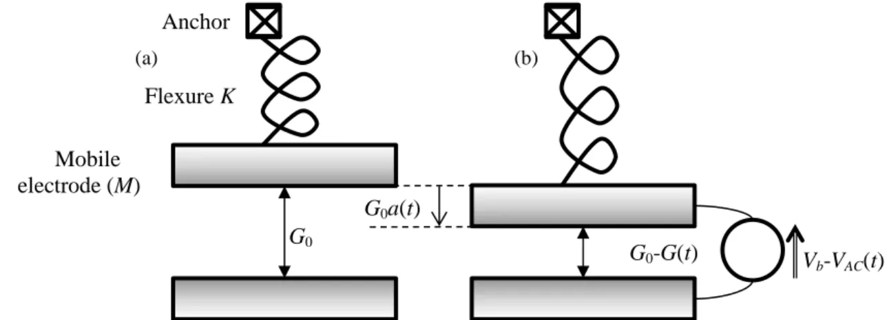
t is applied across the gap. It exerts an electrostatic force on the resonator and sets it into motion. Throughout the paper, the actuation voltage is assumed to be very small with respect to the bias voltage, i.e. VAC V . bThe position of the resonator as it moves across the gap is given by G t
G a t0
, so that a1means that the structure touches the opposite electrode (Fig. 1).
Fig. 1 – MEMS resonator with no voltage applied (a) and in a deflected position (b). Defining the electromechanical coefficient as:
0 3 0 2 e S MG , (1)
where 0 is the permittivity of vacuum, the dynamics of the resonator are governed by:
2 2 2 2 0 0 2 1 b AC d a da a a V V N a Q dt dt (2)where is the Duffing coefficient of the elastic spring, and N a
represents the dependence of the electrostatic force with respect to a. This function depends on the resonator geometry (parallel-plate, CC-beam, cantilever) and also on the effective area of the electrode (the electrode might be smaller than the resonator).Anchor Flexure K Mobile electrode (M) G0 G0-G(t) G0a(t) Vb-VAC(t) (a) (b)
Jérôme Juillard – CentraleSupélec / GEEPS –[email protected] 2
2 2 2 2 2 0 0 2 1 b AC b det d a da a a V V N a V V N a Q dt dt . (3)Fig. 2 – Double-sided configuration. The lower electrode is used for actuation, the upper one for detection.
With these notations, the input capacitance (capacitance between the actuation electrode and the mobile electrode) is equal to:
0 0 0 e in S C a C a G (4)and the output capacitance is equal to:
0
out
C C a (5) where
a is a geometry-dependent function.Typical expressions of ,
a , N a
, K and M are given hereafter for various geometries.Parallel-plate resonator
This case is typically met when a large seismic mass is supported by small flexures. In that case, one may derive K and from a static analysis of the flexures, while M is just the mass of the rigid part. We also have:
2 1 1 N a a (6) and
1 1 a a . (7)Clamped-clamped beam
A clamped-clamped beam (or CC-beam) is a beam fixed at both ends (Fig. 3). In that case, a t
represents the motion of the midpoint of the beam. The beam has the following properties: Young’s modulus E, density , length L, thickness (in direction of motion) h and width b.
The beam is supposed to be initially straight and unconstrained. The in/out electrodes have the same length as the beam (SebL) and the aspect ratio of the device guarantees that the parallel-plate
approximation holds in a cross-section of the beam.
G0-G(t) Vb-VAC(t)
Vb-Vdet
Jérôme Juillard – CentraleSupélec / GEEPS –[email protected]
3
Fig. 3 – Sensing element of the M&NEMS project: a CC-beam between two electrodes. In that case, we have:
3 3 16.56Ebh K L , M 0.397bhL, 2 0 2 0.719G h , (8)
3/ 2 1 0.017 0.523 1 a N a a , (9)
1/ 2 1 0.029 1 a a a . (10)Cantilever beam
A cantilever beam is a beam fixed at one end and free to move at the other end. In that case, a t
represents the motion of the free extremity of the beam. The beam has the following properties: Young’s modulus E, density , length L, thickness (in direction of motion) h and width b. The beam is supposed to be initially straight and unconstrained. The in/out electrodes have the same length as the beam ( Se bL ) and the aspect ratio of the device guarantees that the parallel-plate
approximation holds in a cross-section of the beam.
Jérôme Juillard – CentraleSupélec / GEEPS –[email protected] 4 3 0.257 K L , M0.25bhL, 0, (11)
1 0 783
0.392 0 531 0 114 log 1 1 + . a N a + . + . a - a a , (12)
a 1 0 505. a
0.888 0 201. a
log 1- a . (13)Other geometries
In the case of beam resonators, the reduced order models of the modal force N a
are obtained as in [1], by minimizing the relative error between a numerical estimation of the projection of the electrostatic force on the first beam eigenmode, denoted by w1:
1
2 1 1 w x dx aw N x a
(14)and a model parameterized by θ, N a θˆ
, . The relative error is summed over a set of chosen modal amplitudes a , so that the optimal parameters are given by: i
2 ˆ , arg min 1 i opt i i N a N a
θ θ . (15)For a clamped-clamped beam, provided 1 (the actuation electrode is centered), the model has the following form:
3/ 2
1
1 ˆ , NCC a a a N . (16)For a cantilever beam, provided 1 (the actuation electrode extends to the tip of the beam), it can be chosen as:
1
1 2 3 2 3 1 1 ˆ , , , log 1 CA a N a N a a a . (17) The coefficients CCN and NCA are calculated so that Nˆ 0,
θ N
0 , i.e. the model and theprojection of the electrostatic force coincide when a0. The structure of the model, independently of its parameters, guarantees that the asymptotic behavior (as a goes to 1) of N a θˆ
, is the same as that of N a
, as shown in [1], so that the relative error is bounded across the whole gap.To obtain the parameters appearing in (9) and (12), (15) is solved: this is a trivial linear least squares problem. The error is minimized over a set of 100 values ai of the modal amplitude,
uniformly spaced between -0.99 and 0.99.
Introducing the log function in the ROM of the cantilever beam (17) gives better results than the approach proposed in [1]. This approach was already used in [2].
The same approach can be used to approximate integrals of the form:
1 11
, , p n N a w dx aw x n p
, (18)and thus account for fringing field effects (n p 1), other nonlinear forces (e.g. squeezed-film damping, Van der Waals, etc.). It is also used to compute the approximations used for the capacitance (10) (13), which corresponds to the case n0, p1.
Note that, it is possible to compute N a
with finite element software without having to use the parallel-plate assumption. This calculation is very expensive though. But the same reduced-order modeling approach as above can still be used to fit a model to the numerical estimation of N a
.Jérôme Juillard – CentraleSupélec / GEEPS –[email protected]
5
Electrical equivalent
To derive an electrical equivalent of the system, (3) is linearized, the constant terms are dropped and the bias voltage is assumed large with respect to the other voltages, leading to:
2 2 2 0 0 2 ' 0 b 2 b AC 0 d a da N V a V V N Q dt dt , (19)where 1 in the single-sided configuration and 2 in the double-sided configuration, and the prime denotes differentiation with respect to a . From (5), the motional current is given by:
0 ' 0 0 0
mot b b
i V C a V C N a. (20) It is thus found that:
0 2 2 0 1 1 2 0 m b R C Q N V , (21)
2 2 0 2 2 0 2 0 ' 0 b m b N V C C N V , (22)
2 2 0 1 1 2 0 m b L C N V . (23)The value of N' 0
is 2 for parallel-plate resonators, 0.794 for CC-beams and 0.5 for cantilever beams.References
[1] J. Juillard, G. Arndt, E. Colinet, “Modeling of micromachined beams subject to nonlinear restoring or damping forces”, Journal of Microelectromechanical Systems, vol. 20, pp. 165-177, 2011
[2] J. Juillard, “Analysis of resonant pull-in of micro-electromechanical oscillators,” Journal of Sound and Vibration, vol. 350, pp. 123-139, 2015.