HAL Id: hal-01469082
https://hal.archives-ouvertes.fr/hal-01469082
Submitted on 16 Feb 2017
HAL is a multi-disciplinary open access
archive for the deposit and dissemination of
sci-entific research documents, whether they are
pub-lished or not. The documents may come from
L’archive ouverte pluridisciplinaire HAL, est
destinée au dépôt et à la diffusion de documents
scientifiques de niveau recherche, publiés ou non,
émanant des établissements d’enseignement et de
In situ observation of solidification patterns in diffusive
conditions
Silvère Akamatsu, Henri Nguyen-Thi
To cite this version:
Silvère Akamatsu, Henri Nguyen-Thi. In situ observation of solidification patterns in diffusive
con-ditions. Acta Materialia, Elsevier, 2016, 108, pp.325 - 346. �10.1016/j.actamat.2016.01.024�.
�hal-01469082�
In situ observation of solidification patterns in diffusive
conditions
Silv`ere Akamatsu
Sorbonne Universit´es, UPMC Univ Paris 06, CNRS UMR 7588, Institut des NanoSciences de Paris, Case courrier 840, 4 place Jussieu, 75252 Paris Cedex 5, France
Henri Nguyen-Thi
Aix-Marseille University & CNRS, IM2NP UMR 7334, Campus Saint-J´erˆome, Case 142, 13397 Marseille Cedex 20, France
Abstract
We present a review of recent in situ experimentation studies on solidification front patterns and microstructures in alloys. Front-tracking diagnostics and real-time observation methods using high-resolution optical or X-ray imaging devices currently apply to model transparent systems as well as metallic alloys in thin and bulk samples. On a theoretical basis that spans the physics of nonequilibrium pattern formation and materials science, in combination with time-resolved numerical simulations, conclusive results of both fundamental-and applied-science interest have been obtained on major problems relative to multiscale microstructure selection, morphological transitions, and crystallo-graphic effects during single- and multi-phase solidification. We will mainly focus on the dynamics of cellular, dendritic, and eutectic growth patterns in diffusive-growth conditions, that is, in the absence of convection in the liquid. This can be achieved in (semi-)thin samples, or, for bulk solidification, in the reduced-gravity environment of orbiting facilities. A selection of emerging work on, e.g., faceted growth and adaptive control of solidification patterns will fur-thermore be reported. We conclude by pointing out open questions and new
∗Corresponding author
perspectives for future research.
Keywords: in situ experimentation, solidification, microstructures, microgravity, metallurgy, nonlinear physics
1. Introduction
The prediction and control of solidification microstructures in alloys actively stimulates abundant laboratory research linking fundamental and applied sci-ences. The advancement of in situ experimental methods for real-time obser-vation of the propagating solid-liquid interface during solidification is key to
5
this vast scientific enterprise. Solidification microstructures –modulations of chemical composition, regular arrangements of finely dispersed crystal phases, and lattice defect networks in polycrystals– are a trace, left frozen in the bulk solid, imprinted by growth front patterns. In metals, and nonfaceted materials in general, these self-organizing phenomena are essentially determined by the
10
redistribution of heat and chemical species by diffusion –often “assisted” by convection motions in the melt– and by local equilibrium or fast attachment kinetics at the interfaces. The dynamical origin of solidification microstructures has long been attested [1, 2, 3], and their complexity more and more clearly re-vealed over time by metallurgical studies,but a consistent nonlinear-physics
ap-15
proach of nonequilibrium pattern formation phenomena has been fostered only in the 1980’s [4, 5, 6, 7]. During the last two decades, systematic experimental studies have been undertaken in a coherent theoretical context, implementing high-resolution front-tracking diagnostics and real-time observation methods in polycrystals and multiphase composites on the required time and space scales.
20
In parallel, time-resolved numerical simulations quickly developed [8, 9, 10]. By these combined means, conclusive results have been obtained with unparalleled accuracy on major questions concerning morphology selection and transition processes, microstructural defects, and crystallographic effects during one- and multi-phase solidification, thus opening up to further prospects on both
theo-25
We present a review of recent experimental results obtained by real-time observation methods during solidification of dilute and eutectic alloys. Ma-jor breakthroughs from in situ solidification (shortly speaking) research can be traced back to the implementation, in the 1960s, of thin-sample directional
so-30
lidification of transparent alloys “that freeze like metals” by Jackson and Hunt [11, 12], and further developments during the 1970-1980 decades [13] (also see Ref. [14]). Since the middle of the 1990’s, discoveries have followed an accel-erated pace. Retime observation has been extended to bulk transparent al-loys during directional solidification, and, by taking advantage of high-brilliance
35
X-ray facilities, to metallic alloys. For clarification, we will consider situations where perturbing factors coming from gravity- (or capillarity-) driven convection in the liquid were minimised, thus closely approaching the ideal limit of diffusion controlled growth. We also deliberately place ourselves in conditions close to conventional casting, therefore excluding fast solidification from our report.
Fo-40
cus will be put on experimental studies based on directional-solidification meth-ods performed with thin samples, and, for bulk solidification, in reduced-gravity conditions in orbiting facilities. We will highlight the success of a synergic re-search combining in situ solidification and numerical modelling, which is highly exemplary, and particularly fertile. In these conditions, the morphological
sta-45
bility of dendritic, cellular, and lamellar/rod-eutectic solidification patterns have been carefully tested. Moreover, remarkable growth shapes (doublon, spiral two-phase dendrite) and complex space-time phenomena in drifting and oscilla-tory patterns have been discovered. The strong hisoscilla-tory and boundary-condition dependency of extended solidification patterns has been clearly demonstrated.
50
New insights into initial and transient stages, as well as mild instrumental forc-ing (thermal bias, isotherm curvature) have been gained. Our understandforc-ing of the interplay of the solidification dynamics with crystal-lattice defects, and with the crystallographic anisotropy of the solid-liquid and solid-solid interfaces involved in the solidification process is also deeply improving. Most of the
55
overviewed studies share in common a general-physics approach of solidification front pattern formation and stability, and are directed towards the unraveling
of complex aspects of the nonlinear dynamics involved in the formation of so-lidification microstructures. They also openly keep a tight link with pending questions of great importance in materials science (e.g. columnar vs equiaxed
60
growth, polycrystal and eutectic-grain textures), from which they are obviously inspired, and on which they cast new light. This corpus of experimental find-ings is of essential help for validating fundamental models and existing predictive codes. It should moreover provide a new basis for optimising the modelisation of natural and industrial solidification processes, during which fluid flow in the
65
liquid and plastic deformation in the solid are involved.
This review is structured as follows. We briefly present the general context (diffusion controlled growth experiments in thin samples and in microgravity) in Section 2. In Section 3, novel observation methods are briefly presented. The main results are presented in the following order. Section 4 is dedicated to
70
dendritic and cellular patterns in dilute alloys. It is divided into three parts. In Section 4.1 (thin-sample solidification), particular emphasis will be put on the role of interfacial anisotropy in the stability of dendritic (Section 4.1.1) and cel-lular (Section 4.1.2) patterns. The dynamics of grain-boundary grooves (Section 4.1.3), and a novel method developed for a local adaptive control of solidification
75
patterns (Section 4.1.4) will be briefly presented. In Section 4.2, we will focus on bulk solidification in nearly diffusive conditions, that is, in practice, in micro-gravity (µg) facilities. After a brief report on pioneering work (Section 4.2.1), optical observations of cellular and dendritic arrays in transparent alloys (Sec-tion 4.2.2) will be described. The presentation of X-ray radiography studies of
80
columnar and equiaxed growth regimes in metallic samples (Section 4.2.3) opens up to a brief discussion on possible mechanisms (including convection or advec-tion moadvec-tions in the interdendritic liquid) at play in dendrite-arm fragmentaadvec-tion processes. In Section 4.3, some prospective studies on faceted growth –in par-ticular, polycrystalline silicon– will be mentioned. Eutectic growth is presented
85
in Section 5. It will begin with thin-sample directional solidification of binary eutectics (morphology diagram; Section 5.1.1) and ternary eutectic alloys (spiral two-phase dendrite, three-phase patterns; Section 5.1.2). We present new
in-sight into the problem of the formation of eutectic grains (interphase boundary anisotropy) in Section 5.2. Finally, complex features of lamellar and rod-like
90
eutectic growth in bulk transparent samples will be presented in Section 5.3. Conclusions and perspectives are proposed in the last section.
2. General context
Nonfaceted crystal growth from the melt is practically equivalent to diffusion controlled growth. [The theory of the solidification problem has been presented
95
in many textbooks (e.g. Ref. [9]).] Similar solidification pattern formation phenomena are observed in nonfaceted alloys, independently of their chemical nature –those include metals, salts [15], rare gases [16, 17] and some organic compounds with a low melting entropy (Jackson criterion) [11]. In simple cases, heat is rapidly evacuated (“frozen temperature field”), and solute diffusion in the
100
solid negligible. The solidification dynamics is then dominated by the diffusion of chemical species in the liquid. For growth rates in an ordinary range for bulk solidification (<< 1 mms−1), attachment kinetics at the solid-liquid interface can most often be assumed to be instantaneous. Therefore, in addition to solute diffusion in the liquid, the free-boundary problem includes mass conservation
105
at the moving solid-liquid interface (Stefan condition) and local equilibrium at the interface (and at trijunctions for coupled, multiphase growth). We recall the definition of the diffusion length ld = D/V (with D the solute diffusion
coefficient in the liquid for a binary alloy, and V the propagation velocity of the solidification front), which measures the strength of the diffusive couplings
110
close to the interface (ld typically varies within 10 − 1000 µm). The capillary
length d0 is proportional to the solid-liquid surface tension γ, and is associated
to curvature effects (d0 does not exceed a few 10 nm). Characteristic scaling
lengths of, e.g., cellular and eutectic patterns, are nonlinear combinations of ld
and d0.
115
Explicit theoretical tracking of the nonlinear, multiscale solidification prob-lem can be performed only for a few particularly simple situations (steady-state
patterns, short transients). Paradigmatic cases are the Mullins-Sekerka (MS) analysis of the cellular instability of the planar front in dilute alloys [3], the free dendrite at small undercooling [7], and the Jackson-Hunt theory of lamellar
120
eutectics [12]. For more realistic phenomena, time-resolved numerical simula-tions are required. Front-tracking methods (sharp interface) [18], and, more fre-quently at present, phase-field (PF) models are of current use [8, 10]. On space scales approaching casting conditions, scale-bridging models [19, 20, 21, 22] and numerical automata (e.g. CAFE, Cellular Automaton-Finite Element [23, 24])
125
for polycrystal growth are progressively improved. For quantitative purposes, special attention is also brought to high-accuracy thermophysical measurements [25]. The thus obtained results serve as quantitative references/benchmark data for realistic integrated computational materials engineering (ICME) programs using multiscale numerical simulations. In this overview, key numerical results
130
will be mentioned in correspondence with experimental studies.
In normal gravity, thermosolutal convection during solidification is induced by built-in constitutional and thermal gradients, and/or by instrumental im-perfections (tilted, nonplanar isotherms). The flows in the liquid modify the diffusion layer, and generally prevent the formation of steady solidification
pat-135
terns with uniform features. These effects can be avoided in samples with a reduced size (at least in one dimension). In very thin, flat samples of thickness in the 10µm range, diffusive growth occurs in an essentially two-dimensional (2D) geometry, with good thermal control. Solidification experiments with weak convection can be performed in samples of thickness in the 100 µm range (and
140
also in cylindrical capillaries of inner diameter of less than 1 mm for metal-lic alloys [26]). Suppressing convection motions in bulk samples (also referred to as three-dimensional, or 3D, samples) during solidification is a much more challenging task. Vanishing convective mass transport can be achieved in an orbiting microgravity facility, independently of alloy composition and container
145
shape. Considering the large characteristic times of diffusion controlled growth, long-duration microgravity conditions with reduced parasitic accelerations (g-jitters) are required. Accordingly, dedicated in situ solidification setups have
been installed on board of various space orbiting platforms (e.g. the now re-tired space shuttles or MIR station, or Foton satellites) and more recently on
150
the International Space Station (ISS) or sounding rocket (MASER), under the cooperative control of several space agencies in the world [27]. We will present below several successful real-time solidification experiments under microgravity, in bulk transparent (visible-light optical diagnostics) and metallic (microfocus X-ray) alloys. Perturbing effects induced by gravity during solidification
inves-155
tigated by mean of synchrotron X-ray radiography have been presented in many previous publications (for a review, see, e.g. Ref. [28]).
3. Real-time imaging methods 3.1. Directional solidification
Most laboratory investigations of solidification pattern formation are
car-160
ried out in the presence of a thermal gradient. In directional solidification (DS) properly speaking, crystal growth is performed by pulling the sample at constant velocity V in a fixed temperature gradient G (axis z) between two thermally regulated blocks (Bridgman method). Ordinary G values fall in the 10−100 Kcm−1range, and V is commonly varied between 0.01 and 100 µms−1,
165
depending on the problem under consideration. Directional solidification allows for the formation of steady-state patterns over large time and space scales after relatively short transients. Periodic patterns are characterised by the spatial period or “spacing” λ. In steady-state conditions, the solidification front fol-lows, in average, a given isotherm parallel to the xy plane, and perpendicular
170
to z. Deviations from this ideal situation will be reported below. An alterna-tive way to achieve DS is to decrease the temperatures of both hot and cold zones of the furnace at a given rate by keeping the sample fixed. There is no well-defined steady-state in that case (see columnar growth during casting), but this protocol permits efficient (and easier) image processing when using in situ
175
A basic DS protocol consists of: (i) partial directional melting, and solid-liquid equilibration at rest (V = 0); (ii) pulling at given V until a steady state is reached; (iii) morphological-stability tests upon successive up- or downward velocity changes. Particular attention has to be paid to the initial state
(ho-180
mogenisation of the liquid, crystal selection). The (visible-light or X-ray) images are collected by a digital camera via a suitable optics, and recorded on a PC for further processing and analysis. This procedure is largely inspired by the physics of nonequilibrium pattern forming systems. In brief, we consider steady periodic patterns that are stable over a finite spacing range, at fixed control
pa-185
rameters. Inside the region of stability (stability balloon [30]), a modulated pat-tern [spacing distribution λ(x, y, t)] undergoes a general uniformization process (Section 5.1.1). Outside the stability balloon, the system restabilises into a new symmetry-broken periodic pattern, or displays a complex spatio-temporal dy-namics. This phenomenology has been extensively documented in thin-sample
190
DS (in short, thin-DS), and in 2D simulations (see, e.g., Ref. [31]). Bulk so-lidification is much more challenging, due to the large number of geometrical degrees of freedom.
Isothermal growth of a single crystal in a uniformly cooled sample (also see equiaxed growth) has also been used [13, 32, 33]. This method appears
195
quite simple, but is made difficult, in practice, by long solute and heat diffusion transients and finite-size effects (incidentally, fast changes of undercooling of less than 0.1K in organic materials could be achieved by a Clausius-Clapeyron effect [34, 35, 36]).
3.2. Transparent alloys
200
3.2.1. Model alloys
For real-time observation, DS experiments are most commonly carried out with transparent organic alloys (molecular “plastic” crystals [37]), in particular alloys based on succinonitrile (SCN) [13, 38, 39, 40, 41, 42, 43, 44] or carbon-tetrabromide (CBr4) [12, 45, 46] (also see liquid-crystal systems [34, 35, 47],
205
purified compounds with impurity levels of a few 10−2 mol% or less are used. Trace impurities (in particular, residual gases) with a low partition coefficient slowly accumulating at the growth front can induce substantial perturbations [46, 49, 50, 51].
210
3.2.2. Thin-sample directional solidification
Very thin samples are made of flat glass plates separated by spacers that fix the film thickness w (in the transverse direction y) in the 10 µm range. They are of centimetric dimensions in the sample plane xz. Convection fluxes in the liquid are suppressed by viscous effects at the walls. Solidification occurs in an
215
essentially 2D geometry, as long as the characteristic size of the pattern remains higher than, or comparable with w. The growth of large (single) crystals can be achieved by using a crystal selector [52]. Flat samples of thickness in the 100 µm range are also commonly used, with a marked confined-3D character, and lesser convection reduction efficiency. Real-time imaging of the profile-line of the
solid-220
liquid interface is performed in side view with a standard optics coupled with a digital camera. Transmitted light is used for transparent alloys. The thin-DS method has been recently extended to metallic alloys (reflected-light mode) [53]. Thin-DS can be used for in situ alloy characterisation (measurement of diffu-sion coefficients, capillary lengths, important features of the equilibrium phase
225
diagram, and impurity amount), in particular by quantitatively analysing the initial transient [46, 51, 54]. In a dilute-alloy sample maintained at rest (V = 0), the unmelted solid equilibrates with the liquid at the liquidus temperature Tl.
In steady-state (V 6= 0), the planar front is at the temperature of the solidus Ts
(< Tl). During the solute redistribution transient, the interface recoils over a
230
distance lt= ∆T0/G (∆T0= Tl−Ts) in the thermal gradient [55]. A theoretical
analysis of this transient in a quasistatic approximation was made by Warren and Langer [56]. In bulk samples, the release of latent heat at the interface cannot be neglected, even at low velocities [57].
3.2.3. Bulk-sample directional solidification
235
In recent years, much progress has been made in real-time imaging of so-lidification front patterns in bulk transparent samples. Two major issues must be addressed. The first one concerns the detrimental effects of convection mo-tions in the liquid. This justifies, as explained above, the use of microgravity facilities. The second difficulty is related to the formation of good images of
240
the solid-liquid surface in a top view with sharp contrast and suitable spatial resolution. Two distinct methods developed for eutectic alloys on the one hand, and cellular and dendritic patterns in dilute alloys on the other hand will be shortly presented.
The DIRSOL instrument (Fig. 1a) has been developed for real-time
ob-245
servation of eutectic solidification in (semi-)bulk samples of transparent alloys [58]. The technical characteristics of both the DS bench (G ≈ 100Kcm−1; V = 0.01 − 10µms−1) and the (flat-wall) cartridges are similar to those of thin-sample setups, but the inner thickness of the thin-samples ranges between 300 and 500 µm (much larger than the interphase spacing in eutectic microstructures,
250
which typically falls in the 10 µm range). Real-time observation is performed with a long-distance microscope that focusses the solid-liquid interface in an oblique direction (40 − 50o) relative to the solidification axis, through the liquid
and a glass wall (non-invasive method). Illumination is applied in an oblique way as well, through the solid. A low numerical aperture is used to select light
255
rays from one of the two eutectic phases only, and to form a dark-field image with a nearly white-and-black contrast between the two solids at the interface (effective optical resolution of about 3 µm). Two conditions must be met for achieving a clear picture of the whole front despite the inclination of the micro-scope: (i) the viewing angle must be such that the image plane of the microscope
260
coincides with the image of the solidification front (this optimum angle depends on the refractive index of the liquid; it also maximises the image aspect ratio); (ii) the aperture of the microscope must be low enough to limit the astigmatism inherent in optical devices with planar diopters. Thermosolutal convection can
be avoided (vertical DS setup) for alloys of near-eutectic concentration.
Rep-265
resentative images of lamellar (CBr4-C2Cl6) and rod-like (SCN-DC) patterns
are shown in Figs. 1b and 1c, respectively. More detailed results are presented in Section 5.3. A multi-user apparatus (called “Transparent Alloys”) based on the same optical method as DIRSOL, and dedicated to in situ solidification in microgravity (ISS), is currently being developed by the European Space Agency
270
(ESA) [59]. Recently, another original observation method has been developed by Witusiewicz et al [60, 61]: the image of the solidification front is reflected by a small mirror immersed in the liquid inside the sample (and inclined by 45owith
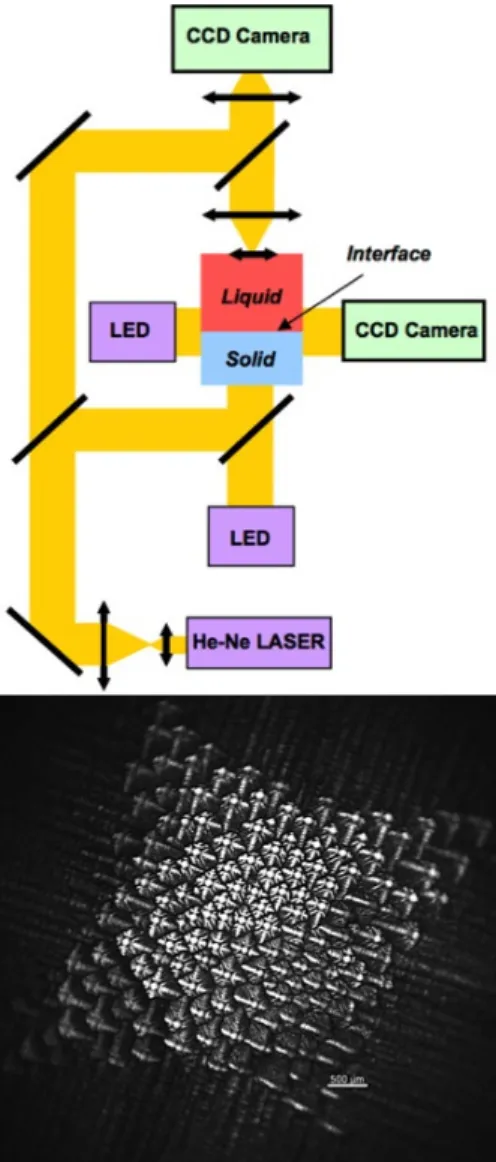
respect to the solidification z), and focused onto a long-distance microscope. The Directional Solidification Insert (DSI) of the multi-user DECLIC
(DE-275
vice for the study of Critical LIquids and Crystallisation) facility has been devel-oped by the French Space Agency (CNES), and installed on the ISS in August 2009 as part of a joint NASA/CNES microgravity-research program [62]. Based on a similar principle as the pioneering MOMO apparatus [63], DSI is dedicated to real-time observation of DS front patterns in bulk samples of dilute
trans-280
parent alloys (Fig. 2). The samples are 10-cm long cylindric fused-quartz tubes with an inner diameter of 1 cm, filled with a dilute SCN-based alloy (the inter-cell or dendrite spacing usually falls in the 100 µm range). This makes possible long-time solidification of extended 3D patterns over several centimetres in well-established steady state, free of noticeable finite-size effects (G = 10−30Kcm−1;
285
V = 0.1 − 30µms−1). A volume-compensation system accommodates density variations associated to phase changes in the sample. An endoscopic optics is immersed in the liquid and automatically focuses the solidification front in a top view. The light source is placed at the cold end of the sample, just behind an optically flat glass window. In the main observation mode, axial observation of
290
the solidification pattern takes advantage of the complete transparency of the medium. The light propagates through the solid, and is refracted when pass-ing through the (patterned) solid-liquid interface. The image of the interface is formed on a grey-level CCD camera. In addition, a Mach-Zehnder interferome-ter is set along the visualisation axis. Ininterferome-terferograms at the solid-liquid ininterferome-terface
Figure 1: a) Principle of the DIRSOL apparatus: oblique observation (angle θ) of the solid-liquid interface during DS of a transparent eutectic alloy. z: direction of the thermal gradient G and of pulling (velocity V ). y: normal to the glass walls. The optical axis lies in the yz plane. w: thickness of the sample. L: lateral width of the sample (L >> w). b) Lamellar pattern in a w = 350-µm thick sample of near-eutectic CBr4-C2Cl6alloy (V = 0.37 µms−1).
Bright (dark) lamellae: α (β) phase. c) Rod-like pattern in a 350-µm sample of a eutectic succinonitrile-d,camphor alloy (V = 0.035 µms−1). Bright spots: DC fibers (the SCN matrix
provide a precise 3D image (contour lines) of the growth shape [64]. An exter-nal optics for side-view observation also gives useful information on the average shape of the interface along the thermal axis. The operator scientists have the possibility to follow and remotely control the experiments by tele-science in near real-time conditions. Six runs of 2 − 3 weeks each were performed from April
300
2010 to April 2011. Two solidification runs have been performed on ground with the same control parameters as in the µg experiments. Some of the results are presented in Section 4.2.2.
3.3. Metallic alloys
Real-time observation of the solidification process in non-transparent
ma-305
terials (metals and semiconductors) has been a critical issue for a long time. Standard investigation techniques, such as quenching or decanting, do not pro-vide the interface evolution over time in 3D, but gives only a “frozen” picture of the solid microstructure. A first attempt to follow in situ the interface be-haviour during solidification was made in a seminal microgravity study of
time-310
dependent solidification phenomena in large metallic samples of Sn-Bi alloys (Mephisto apparatus) [65, 66]. In that program [which was conducted in the now retired shuttle, United States Microgravity Payload (USMP) missions] a sophisticated DS furnace was used to process three samples in parallel, and gain complementary information about alloy composition, actual growth
veloc-315
ity and temperature gradient at the interface. The most salient feature was the implementation of a real-time thermo-electric (Seebeck) diagnostic between two solid-liquid interfaces, one providing a fixed temperature reference, while the other was allowed to move at controlled V . A strong Seebeck signal was obtained with Sn rich alloys doped with Bi (1-mol% range). In planar-front
con-320
ditions, the Seebeck signal is directly proportional to the interface undercooling. The analysis was more complicated in cellular or dendritic configurations. Other experimental methods for front tracking in metallic alloys include: (i) side-view observations of the solidification front position in cylindrical metallic samples during DS through a transparent aerogel mould (see, e.g., Ref [67]), and (ii)
Figure 2: Top: principle of the optical diagnostics of the DECLIC-DSI apparatus; yellow lines: optical paths. CCD cameras: top- and side-view imaging. He-Ne laser: interferometry imaging. Colour online. Bottom: dendritic array observed with DECLIC-DSI on board of the ISS (SCN-0.24wt% camphor; V = 30 µms−1; G = 28Kcm−1). White bar: 500 µm. Courtesy N. Bergeon.
ultrasonic detection (see, e.g., Ref [68]). Those techniques are, however, lim-ited to global information on the solidification front dynamics, and do not give reliable access to microstructural features.
This difficulty could be partly circumvented in alloys, in which the solid-liquid interface is strongly sensitive to a thermoelectric effect (Peltier interface
330
demarcation technique). A short-current pulse of high intensity is transmitted through the solidifying sample, thus leaving a thin frozen-in compositional trace in the solid, which more or less delineates a contour of the solid-liquid interface. A time sequence of electric pulses thus results in a spatial series of compositional marking, which, after proper etching of a longitudinal section, reveals the
inter-335
face position and shape at successive times during growth [69]. This technique has proven its capabilities for the study of faceted growth of Bi-Sb alloys [70].
For deeper insight into metallic-alloy solidification, a major breakthrough was the use of high-intensity X-ray sources. Indeed, the features (intense and coherent beams) associated with modern synchrotron radiation (SR) resulted
340
in a substantial extension of X-ray imaging capabilities to high (spatial and temporal) resolution, and 3D tomographic images. This allows one to gain key information on crystal growth-related phenomena that was not available hith-erto. Synchrotron-radiation X-ray imaging techniques can be basically divided into two main types:
345
1-Bragg diffraction imaging, such aspolychromatic (white-beam) X-ray topog-raphy, allows for a characterisation of the long-range strain field around crystal-lographic defects, as well as weak distortions in bulk crystals [71, 72, 73, 74, 75]. X-ray topography has been widely used for the study of the interplay between crystal defects (dislocations, twins, stacking faults, inclusions or precipitates)
350
and crystal growth mechanisms [76]. In brief, when a crystal fulfils the Bragg conditions for some of the wavelength(s) of the white beam, part of the incoming light is diffracted in specific directions. Crystal-lattice defects are revealed by intensity variations associated to local mechanical distortions (lattice parameter variation or lattice rotation) of the crystal. In practice, several diffracted spots
355
crystal grain. The analysis of the different diffraction spots for a given crys-tal gives complementary information about strains and misorientations in the solidification microstructure [74, 77]. The high SR flux makes it possible to record simultaneously several diffracted images (1-s exposure time) on the same
360
detector with a high sensitivity (< 10−6− 10−3) and a spatial resolution in the micrometer range, and to use relatively large samples (a few cm2× 0.1cm).
2-Radiography techniques are based on the local changes in the amplitude of a transmitted X-ray beam due to differential absorption by an inhomogeneous sample [78, 79, 80, 81]. (Fast and ultra-fast tomography for 3D imaging in small
365
cylindrical samples has hardly been used for in situ study of the solidification dynamics in proper; it will not be addressed in this review [82, 83, 84, 85].) Since the early 2000s, high-brilliance SR, combined with the most advanced X-ray optics and cameras, makes it possible to capture real-time video sequences of flat (thickness of 150 − 200µm) metallic alloys during DS. The image contrast
370
results firstly from the segregation of chemical species (see, e.g., Al-Cu) and sec-ondly from density difference between the solid and the liquid (see, e.g., Al-Si, and pure Si). The principles of SR-based radiographic acquisition methods can be simply recalled as follows. A monochromatic X-ray beam illuminates the sample. The transmitted beam is collected by a 2D detector (basically a CCD
375
camera equipped with a high resolution scintillator) behind the sample. Radio-graphs with image resolution down to 100 nm at frame rates of 20 Hz could be obtained in the best conditions. Breakthrough observations were obtained on columnar growth [86], columnar-to-equiaxed transition [87, 88], dendrite frag-mentation [89, 90] (see Section 4.2.3), bending of secondary arms [91], equiaxed
380
growth [92], and the influence of convection during planar-front solidification [93] (details on DS devices adapted to SR facilities can be found in those refer-ences). Globally, SR-imaging studies pinpointed the strong influence of gravity (convection and buoyancy forces) on the solidification microstructures in normal gravity environment.
385
Recent developments of the microfocus X-ray technique, along with increas-ingly powerful X-ray sources and sensitive detectors, have led to vast
improve-ments in the performance of laboratory radiography setups (see, e.g., Ref. [94]). In the framework of an ESA project, a novel microfocus X-ray radiography fa-cility dedicated to the study of the solidification of Al-based alloys has been
de-390
veloped, and successfully utilised during MASER-12 sounding rocket campaign [95], and parabolic flight [96]. This compact facility, called XRMON-GF (X-ray MONitoring of solidification process - Gradient Furnace), comprises a Bridgman furnace and an X-ray imaging device. The latter consists of a specific microfo-cus X-ray tube, with a 3µm focal spot (Viscom AG, Germany; in cooperation
395
with DLR, German Aerospace Center), and a digital camera system (Vosskuhler 11000) with a CCD sensor (24 × 36mm2) adapted for X-ray usage [95]. Images
(2048x1334 pixels) can be captured at a rate up to 6 Hz. Experiments have been performed with adequate flux to capture at 2 Hz during MASER-12 mission. While synchrotron sources mostly provide parallel beams, a microfocus source
400
delivers a cone-shaped beam, and permits an image magnification up to a factor 15, depending on the source-to-sample and source-to-detector distances. In the MASER-12 experiment, a factor 5 for the image magnification was used to en-able one to analyse the dynamics of the whole solidification microstructure of the sample. A similar apparatus has been very recently developed in parallel by
405
the german space agency DLR (Deutsches Zentrum f¨ur Luft- und Raumfahrt), which is mainly dedicated to the study of equiaxed microstructure evolution in nearly isothermal conditions in thin metallic samples [97]. This newly developed apparatus has not been used in microgravity environment up to now.
4. Dendrites and cells
410
4.1. Purely diffusive conditions: thin samples 4.1.1. Dendritic and seaweed patterns
The dendrite is the most prevalent morphology of diffusion controlled crys-tal growth in mecrys-tallic and nonfaceted alloys. Complex microstructural features of great practical impact such as microsegregation, intermetallic precipitation,
415
the characteristic size distribution of dendritic structures. A dendrite is a finger-like, single-crystal growth shape, which propagates at constant velocity V along a particular (high-symmetry) crystal axis. The overall profile of a steady-state dendrite can be approximated, for convenience, by a paraboloid near the tip (tip
420
radius of curvature ρ), but the detailed shape is, in fact, rather complex, and depends on interfacial-anisotropy parameters. In addition, secondary branching occurring at a distance at the rear of the tip is responsible for the typical tree-like aspect of the dendrite. The theoretical analysis of the dendrite problem is a long story. It started in the late 1940’s with the Ivantsov theory of the
nee-425
dle crystal [98], and was completed about 40 years later, when a self-consistent solution of the problem with finite capillarity could eventually be found. A “microsolvability” condition was obtained, which states that the selection pa-rameter σ∗ = d0D(ρ2V )−1 is a constant of the material, and depends on the
anisotropy of the solid-liquid surface tension [6, 7, 99]. Numerical simulations
430
have essentially confirmed this theoretical scheme [100, 101].
Interfacial anisotropy designates the dependence of the free energy γ of the considered interface on its inclination with respect to the crystal lattice. This crystallographic anisotropy is determined on an atomic scale, and naturally respects the symmetries of the crystal (see [102, 103] and refs. therein). For
435
some applications, it is convenient to refer to the polar representation of the anisotropy function γ(ˆn) (γ-plot), where ˆn is the normal unit vector of the interface (see, e.g., Ref. [104]). In a nonfaceted system, solid-liquid anisotropy coefficients do not exceed a few percents, and are difficult to measure in situ [13, 33, 103, 105].
440
An experimental demonstration of the dependency of dendritic growth on crystallographic anisotropy has been brought by the discovery of the so-called seaweed structure by 2D numerical simulations [106, 107, 108] and thin-DS ex-periments [52]. The key experimental point is that in very thin samples, solidi-fication patterns qualitatively depend on the orientation of the growing crystal
445
with respect to the solidification device: the effective 2D anisotropy function is given by the cross-section of the 3D γ-plot of the solid-liquid interface by the
sample plane. In Ref. [52], axial dendrites were observed when a [100] axis of the bcc crystal was aligned with the main growth axis. In a first approximation, the 2D anisotropy was of the standard cos4θ form (also see Refs. [38, 41, 109]).
450
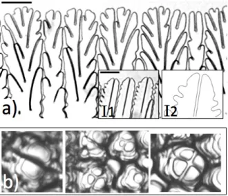
In contrast, by selecting a crystal with a (three-fold symmetry) [111] axis per-pendicular to the sample plane, dendritic patterns were not observed, but were replaced by unsteady seaweed structures (Fig. 3a) [52, 110, 111]. Close to such an orientation, the fourfold anisotropy vanishes, and the 2D system is es-sentially isotropic (assuming that anisotropy components of higher order are
455
negligible). Fundamentally, below a certain anisotropy level, the ordinary den-drite is replaced by a split-denden-drite growth shape called doublon (two mirror-image asymmetric fingers separated by a thin liquid channel; inset I2 in Fig. 3a). The morphological features of the doublon are uniquely determined at given control parameters, like those of the standard dendrite, except that its
460
growth direction is free, hence the unsteadiness of seaweed patterns. Steady doublons can be stabilised by a small anisotropy (inset I1 in Fig. 3a), and co-exist with dendrites. Doublon-like shapes have been observed in 3D, at least transitorily, during isotherm growth [112] and in DS (Fig. 3b). The formation of twinned doublons (rather than dendrites) could also contribute to the formation
465
of “feathery” microstructures in aluminium alloys [113].
Some more complicated dendritic-growth phenomena in cubic crystals can-not be explained by considering a single fourfold component in the γ-plot (see, e.g., Ref. [114]). In particular, changes in dendritic-growth directions and mor-phologies have been observed as a function of the undercooling in transparent
470
systems [115], and of the concentration in Al-Zn alloys (ex situ observations) [116]. Plausible explanations have been proposed in both cases (competition between kinetic and capillary effects in the first case [117], and a variation of the γ-plot as a function of the Zn concentration in the second), but our under-standing remains incomplete. Further progress can be expected due to the
de-475
velopment of atomic-scale simulations for calculating the solid-liquid surface free energy and its anisotropy [102, 118]. The calculated γ-plot (and the anisotropy of the kinetic coefficient) of pure nickel could be included in phase-field
simula-Figure 3: a) Seaweed pattern during thin-DS of a transparent (CBr4-8mol%C2Cl6) alloy
(V = 20 µms−1; G = 110 Kcm−1). A [111] axis of the crystal was nearly perpendicular to
the sample plane. The growth direction (z axis) is vertical. Insets: Stable doublons in a CBr4
-4mol%C2Cl6 alloy (I1), and in a numerical simulation (I2; courtesy T. Ihle). Bars: 100 µm.
For details, see Ref.[52]. b) Transient (3D) doublons, triplons and quadruplons observed in top view during a bulk-DS experiment in DSI-DECLIC (N. Bergeon).
tions, which were compared to ex situ metallographs [119]. Systematic studies combining molecular dynamics calculations of the γ-plot, phase-field modelling
480
and in situ experiments with full information on the crystal orientation are still lacking, to the best of our knowledge.
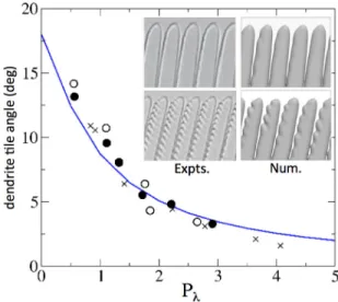
In DS, the growth of dendritic arrays is affected by the thermal gradient and the diffusive coupling between neighbouring dendrites [120, 121]. Special attention has been brought to tilted-dendrite patterns in (cubic) crystals such
485
that the [100] axis (or its projection in the sample plane) is inclined, that is, the direction of a minimum of γ in the xz plane makes an angle θ0 from z.
The dendrite tilt angle θ is then systematically smaller than θ0, increases when
V or the dendritic spacing λ increase, but is quite insensitive to G. In fact, θ is found to depend on the sole quantity Pλ = λ/ld = λV /D, independently
490
of the thermal gradient G, and tends to θ0 for, say, Pλ > 10 (Fig. 4) [122].
This behaviour has been observed in various compounds [123], and confirmed numerically [122, 124, 125]. Empirical scaling laws have been proposed in order to account for the influence of sidebranching at large Pλ values [123]. For
particular crystal orientations such that two maxima of γ point more or less
495
symmetrically about z, unsteady “degenerate” patterns are observed [52] (also see Refs. [126, 127]), which resemble to, but must not be confused, in principle, with the (vanishing-anisotropy) seaweed patterns. The morphological transition between tilted dendrites and degenerate patterns as a function of the growth rate could be a good indicator of the level of anisotropy, and/or the relative
500
strength of capillary and kinetic anisotropies. The dynamics of tilted-dendrite arrays plays a crucial role during grain growth competition in polycrystals (see, e.g., [125, 128, 129, 130]).
Let us finally briefly consider the (still largely open) problem of dendrite sidebranching [131]. There is a clear consensus about the λsb ∼ ρ scaling
be-505
haviour of the sidebranch spacing λsb [32, 38, 39]. Other noticeable aspects
are: 1-The onset of sidebranching critically depends on the shape of the den-drite [41]. Some observations indicate that denden-drites with a “pointed” shape that substantially deviate from a parabola (and plausibly stabilised by a kinetic
Figure 4: Tilt angle of DS dendrites (measured from the main growth axis z) as a function of P´eclet number Pλ(see text). Symbols: experimental (crosses) and 3D numerical (circles)
data. Line: empirical scaling-law. Typical experimental and numerical images are shown in the insets. Courtesy A. Pocheau, M. Georgelin and J.M. Debierre –for details, see Ref. [124] and refs. therein.
anisotropy) are less sensitive to sidebranching [52, 132]. More importantly,
side-510
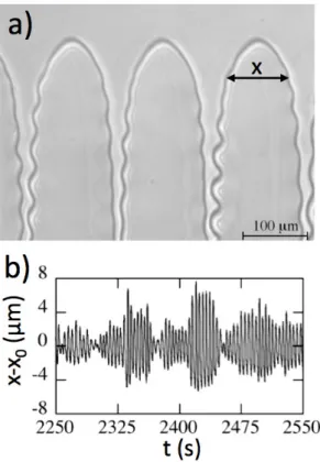
branching of 3D dendrites occurs along the so-called “fins” (see Section 4.2.1). 2-The sidebranching instability is noise-dependent. Under certain conditions (DS), a resonant, synchronised oscillatory instability seems to arise, at least in the form of localised bursts (Fig. 5) [133, 134], thus delivering periodically, and symmetrically spaced secondary branches. Regular sidebranching could be
515
sustained over long times by external excitations ([39, 135]). There is, however, no clear experimental results substantiating a conjectural deterministic dendrite sidebranching process, to the best of our knowledge [136]. 3-The growth direc-tion of well-developed secondary branches depends on the crystal anisotropy and the direction of the main dendritic trunk. 4-A strongly nonlinear
compe-520
tition dynamics of sidebranches starts at a relatively short distance from the tip [20, 137]. This coarsening process controls the ternary branching (tail in-stability) by which a new dendrite can grow and fill in the space between two neighbouring dendrites.
Figure 5: Sidebranching of dendritic fingers during directional solidification of a succinonitrile-based dilute alloy (G = 78Kcm−1; V = 15µm−1). a) Snapshot of the analysed growth pattern. b) Amplitude x − x0 of the fluctuations of the width x of a dendrite in the x
direction (x0: average width) at a fixed distance from the tip as a function of time t. There
is evidence of the occurrence of bursts of 4 to 15 oscillations. Courtesy: A. Pocheau, M. Georgelin (see Ref [133]).
4.1.2. Cell-to-dendrite transition
525
In directional solidification, dendritic arrays arise from a cellular instability of the planar front above a threshold velocity Vc (for an experimental
inves-tigation of the early stages of the cellular instability, see Ref. [54]). For V slightly above Vc (Pλ < 1), the system restabilizes into shallow-cell patterns,
the dynamics of which is generally strongly nonlinear [50, 138, 139, 140, 141]
530
(for more sinusoid-like cells in a mesomorphic system, see Ref. [47]). From thin-DS studies, it was concluded that (i) a finite amount of interfacial anisotropy is needed to stabilise steady cell patterns; (ii) stable axial-cell patterns are ob-served within a finite interval of intercell spacing values at fixed V , which is limited by period-doubling (oscillatory or steady) instabilities [141, 142]; (iii)
535
split-cells (or doublets) can be observed at large cell spacings [142, 143] (for a numerical analysis, see Ref. [144]).
When V is increased, the shape of deep axial cells evolves from a smooth, rounded finger [109, 145] –theoretically analogous to a Saffman-Taylor finger in viscous flow [121]– to a more pointed, dendritic profile with sidebranches.
540
This cell-to-dendrite transition not only depends on V and G, but also on the cell spacing λ, and the interfacial anisotropy. Numerical evidence has been brought that for a relatively large anisotropy, the transition from deep cells to dendritic patterns occurs continuously along a single branch of solutions upon varying V and/or λ, whereas, for a low anisotropy, the two shapes correspond
545
to two separate branches of solutions [121]. This result can serve as a basis for explaining a hysteresis in λ(V ) curves measured experimentally upon increasing or decreasing V . It is also clear experimentally that axial-dendrite arrays possess a strikingly large stable interval of λ [146]. This interval is limited by ternary branching (upper limit), and (at least in 2D) a period-doubling instability that
550
leads to the elimination of one dendrite out of two (lower limit) [147].
4.1.3. Grain boundaries
The formation and motion of grain boundaries (GBs) during growth is a major issue in metallurgy. Ordinary, large-misorientation GBs with a large free
energy are decorated by a thin wetting layer (wet GBs) when put in contact with
555
the liquid [148], and are very mobile in the solid down to temperatures much lower that the melting temperature. In a thermal gradient, wet GBs rapidly mi-grate and reach an equilibrium configuration, thus running perpendicular to the solid-liquid interface [149]. Incidentally, the shape analysis of the solid-liquid meniscus (groove) at the intersect with a GB is a well-known method for
es-560
timating interfacial free energies [150, 151, 152]. In contrast to ordinary GBs, subboundaries (SBs) with a low interfacial energy are practically immobile in the solid. Some insight into the question of the formation of SBs during growth above the cellular threshold was provided by a pioneering study by Grange et al. [71] (synchrotron X-ray topography), who were able to visualise the
organ-565
isation of (bunches of) dislocations in the solid associated to the solidification of metallic alloys. During deep-cell growth, dislocations remain attached at the triple contact line between the liquid, the crystal and the container wall. They grow passively, until they arrange themselves (possibly under the effect of a thermal stress) and form a SB. This phenomenon can repeat itself during
570
growth, and cause a progressive polygonization of the initial single crystal. Dynamic polygonization also occurs during slow growth (planar front) [153]. A theoretical analysis of this phenomenon has been made on the basis of in situ observations during thin-DS [149]. It predicts that, due to their coupling with the movements of the solidification front precursory to the Mullins-Sekerka
575
instability itself, the characteristic spacing between SBs decreases with V ap-proximately as V−1/2. Once formed, SBs align onto a low-energy plane, and intersect the solid-liquid interface obliquely. Therefore, SB grooves move later-ally during solidification. Finlater-ally, there is some indication that, at low velocity, the SB-groove drift is fully determined by the (strong) anisotropy of the SB,
580
but vanishes as V approaches Vc due to the interaction of the SB groove with
4.1.4. Local control
Active control of solidification microstructures is a challenging subject in en-gineering metallurgy. For both laboratory and application purposes, attempts
585
to produce regular microstructures over long solidification distances can be made by implementing predefined experimental protocols based on directional-solidification techniques. Such global-control techniques still remain only partly effective, and poorly reproducible. In contrast, a local adaptive control of solid-ification structures can be achieved by using real-time, micron-scale
perturba-590
tions. A method in transparent alloys, first introduced by Qian and Cummins [39], consists of focussing a collection of light (UV or laser) spots in the vicinity of the solid-liquid interface [54, 147]. Heating due to partial light absorption by the liquid modifies the local shape of the thermal field, and slows down the solidification (or melts back the solid) on a 5 − 50 µm scale, depending on the
595
injected power and the focussing optics. During thin-DS, it was possible to impose a“pre-patterning” of a planar interface, and to guide the system toward a cellular pattern of chosen periodicity within the stable range. Periodic ar-rays of doublet-cell structures have also been obtained for values of the cellular spacing at which they do not spontaneously appear from a MS instability of
600
the planar front, but for which their stability is duly demonstrated experimen-tally with full agreement with phase-field simulations [143]. More specifically, in an experimental and numerical proof-of-concept study [155], a feedback-control scheme was applied to stabilise deep-cell patterns with a (small) spacing outside the natural stability domain, that is, more precisely, below the period-doubling
605
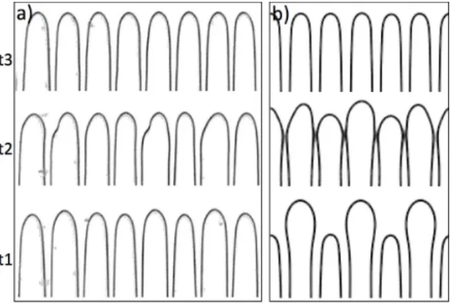
instability threshold mentioned above (Fig. 6). Other possible applications in-clude the space-time control of eutectic growth patterns [156]. Extending such methods to bulk (poly)crystals [157] still remains under prospect.
4.2. Near-diffusive conditions
4.2.1. Pioneering studies in microgravity
610
Microgravity experimentation remains an irreplaceable way to study the formation of solidification microstructures in bulk containers in near-diffusive
Figure 6: Feedback control of a small-spacing cellular pattern. a) Thin-DS experiment (dilute SCN-coumarin 153 alloy; V = 4.6µms−1; G = 10Kcm−1). A numerically addressable device focuses laser spots (not visible) in the liquid just ahead of the cell tips that overhang the average position (local heating). Horizontal dimension: 0.8 mm. b) Phase-field simulation (courtesy A. Karma). Control off (t1): the cell pattern is undergoing a period-doubling instability (elimination of one cell out of two). Control on: transient stage (t2) and stabilised pattern (t3). For details, see Ref. [155].
conditions. By comparison, solidification studies in ordinary laboratory condi-tions reveal important effects associated to gravity [28]. A pioneering, inspiring series of microgravity studies has been carried out by Glicksman and coworkers
615
more than thirty years ago [13, 158]. The Isothermal Dendritic Growth Ex-periment (IDGE) was developed specifically to test dendritic growth theories by performing measurements with ultrapure succinonitrile (SCN) and pivalic anhydrid acid (PVA) under strictly diffusion-controlled conditions. The IDGE instrument was flown three times (from 1994 to 1997) aboard the space shuttle
620
Columbia at a mean quasi-static acceleration of about 0.7 × 10⁻⁶g0 (g0:
nor-mal gravity) [159, 160, 161, 162]. This series of experiments provided a huge quantity of experimental documents, showing dendritic solidification at various undercoolings. The dendrite tip velocity V and radius ρ were measured as a function of the imposed undercooling, and a test of the theory was performed by
625
examining the variation of the P´eclet number P = ρD/V as a function of the un-dercooling. Good repeatability of the experiments was established, bringing the
first solid evidence of dendritic growth fully governed by heat diffusion in a pure substance. Interestingly, P´eclet numbers measured under reduced gravity were substantially different from terrestrial data, and much closer to the theoretical
630
predictions. A slight discrepancy at low undercooling in µg experiments was at-tributed to residual convection in the melt or a finite-size effect [163]. The value of the selection constant σ∗, estimated over a large undercooling range, did not show significative deviation between microgravity and laboratory measurement, but exhibited a slight decrease at large undercooling (note that the analytical
635
scaling theory of dendrite growth was derived under a small-undercooling hy-pothesis). In brief, while the Ivantsov law is substantially affected by convection motions (and finite-size effects), the ρ2V = cst scaling law is quite robust, at least in a pure substance, against mild perturbations [36, 164]. This experi-mental campaign was a first, seminal success for further microgravity science in
640
solidification. (As a complementary approach, mild natural convection effects were probed in dedicated setups [165, 166, 167].)
For completeness, let us also mention some remarkable results obtained in laboratory conditions. A fully 3D morphological study of dendrites growing in rare gases has been performed by Bilgram and coworkers (Fig. 7a) [17, 168, 169]
645
(also see [16]). Similar measurements have been done with solutal dendrites in binary alloys (Fig. 7b) [166, 170]. Experimental evidence was given that the basic shape of a 3D dendrite slightly departs from a paraboloid in the tip region. At a larger distance from the tip, a clear change of the basic dendrite morphology is observed: longitudinal “fins” develop, that is, the cross-section of the dendrite
650
is no longer a circle, but exhibits a number of protruding bumps (four as concerns [100] dendrites in cubic crystals), which depends on the symmetry of the crystal and the growth axis. This agrees well with theoretical [171] and numerical predictions [100, 101].
Finally, in a remarkable work by Dupouy and coworkers (post-mortem
obser-655
vations of Al-Cu samples solidified during the D1-Spacelab mission; see Ref. [172]), the difference between space and ground samples showing very different primary spacings and dendritic-array morphologies was thoroughly analysed. This work
Figure 7: Free-dendrite growth. a) Pure xenon (reprinted from Ref. [168], with per-mission from EDP Sciences; http://epljournal.edpsciences.org/). b) Succinonitrile-0.0086 mol%acetone alloy (reprinted from Ref. [170], Copyright 2012, with permission from Else-vier).
has been further extended to the influence of gravity on eutectic-dendritic and cell-dendrite transitions [173, 174]. More recently, the influence of convection on
660
the columnar-to-equiaxed transition was studied based on microgravity experi-ments carried out in the Material Science Laboratory (MSL), in the framework of CETSOL (Columnar-to-Equiaxed Transition during SOLidification process-ing) project of ESA [175]. Further in situ and real-time characterisation of space experiments is still required to deepen our understanding of more complex
mi-665
crostructural transitions and periodic or unsteady phenomena during transient stages or under fluctuating thermal conditions. For this purpose, a new gen-eration of space facilities has been developed, which integrate advanced in situ diagnostics giving access to real-time information. In the following, we present a selection of outstanding results obtained during recent space missions, carried
670
out on different facilities and devoted to the study of directional solidification with in situ observation.
4.2.2. Large-scale dynamics of cellular arrays in bulk samples
Real-time observation of cell and dendrite arrays in bulk transparent-alloy samples has been performed in the DSI instrument, installed on the DECLIC/CNES
675
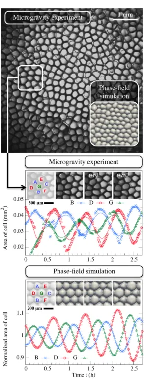
facility of the ISS (Section 3.2.3). Thanks to a drastic reduction of convection effects, microgravity experiments have allowed to create spatially extended so-lidification patterns with a relatively uniform spatial distribution, as required for benchmark data and for analysis of the fundamental mechanisms of pattern formation, and spacing selection [62]. Unprecedented observations of secondary
680
instabilities of cellular patterns have thus been made possible [57, 176]. In the DSI experiments, cellular patterns with a local hexagonal order presented a marked topological disorder on a large scale, which persisted over the whole solidification time (Fig. 8), and was accompanied by cell-splitting and/or elimi-nation events. In some conditions, an oscillatory mode has been identified within
685
a narrow range of growth parameters (including the intercell spacing) –note that periodic oscillatory patterns had been previously observed and analysed in de-tail in 2D cellular and dendritic patterns in thin samples (see Sections 4.1.2
above, and 5 below), but not in 3D experiments during DS. Cells were observed to oscillate with a well defined time period, within experimental accuracy, but
690
the oscillations were spatiotemporally uncorrelated at long distance. In (scarce) domains displaying a pronounced hexagonal order, the oscillating mode was shown to correspond to an alternate oscillation of the three sub-lattices of the hexagonal arrangement with a phase relation of approximately ±2π/3 (Fig. 8). This mode had been previously predicted in numerical simulations of perfectly
695
hexagonal cell structures [177, 178, 179]. In the experiments, small squared-ordered domains have also been observed, with an alternate oscillation of two sub-patterns. In conclusion, the irregular character of the oscillations appears to be essentially related to the spatial disorder of the cell pattern (also see similar observations in rod-like eutectic patterns; Section 5.3). Incidentally, transient
700
doublons (and “multiplons”) have also been observed during DSI experiments (Fig. 3b). These observations illustrate the complexity of the dynamics of cellular patterns in a 3D geometry.
Quantitative measurements of cell-spacing distributions in DSI experiments evidenced a marked influence of finite-size effects on the cell-pattern dynamics
705
and spacing-selection processes. Clear light can be cast on this analysis by not-ing that, due to the different heat conductivity of the three media in contact –the solid, the liquid and the container walls– the isotherms, thus the solidification front, are generally not planar in bulk samples. They present a finite curvature on a scale comparable to that of the container diameter, even at rest (V = 0).
710
This instrumental effect, which is not specific to the DSI instrument, cannot be avoided, except for very special situations. Moreover, it is not smoothed out under microgravity. The curvature of the isotherms varied as a function of V during DS, due to the release of latent-heat and accumulation of solute. Along the curved front, cells are forced to drift toward, or outward the centre of
715
the cylindrical sample, depending on the sign of the curvature (for an inspiring study in 2D, see [180]; also see Section 5.3). This is probably the main source of disorder in cell patterns. It is important to stress that only in situ experimental studies are capable of revealing the qualitative and quantitative effects of
non-Figure 8: Microgravity experiment: top view observation of an oscillating cellular growth pattern (DECLIC-DSI experiments onboard ISS; SCN-0.24%wgt Camphor; V = 1µms−1;
G = 19Kcm−1). Note the high disorder of the pattern (also see the phase-field simulation in the inset). Framed area and arrow: short-range correlation of the oscillations; three sub-groups of cells oscillate with a mutual phase difference of ±2π/3. This behaviour is clearly identified32
planar isotherms during solidification. Test experiments that were performed
720
with a device similar to DSI under terrestrial conditions gave clear evidence that the deformation of the solidification front was dramatically increased when coupled with fluid flow. In unfavourable cases, at pulling velocities above the (nominal) cellular threshold, the cellular instability remained localised at the center of the sample [181]. By increasing V , the cellular structure propagated
725
radially, and a non-uniform microstructure was eventually established, with a smooth region persisting near the wall. As stated above, this dramatic effect was successfully suppressed under microgravity conditions.
4.2.3. Dendrite fragmentation
The formation of columnar microstructures during casting is favourable in
730
practice when directional mechanical properties of the solidified material are required –notably for turbine blades. In contrast, equiaxed microstructures provide more isotropic properties, and are interesting for, e.g., automotive and biomedical components. For an improved control of the solidification process and thus of the final properties of structural materials, a better understanding
735
of the columnar to equiaxed transition is therefore crucial. According to a most commonly admitted scenario [182], new dendritic grains form during casting via a process of secondary-arm fragmentation, followed by the transportation of fragments by convection or buoyancy in the liquid far from the leading colum-nar front (we do not consider inoculated alloys with intensionally added foreign
740
particles serving as easy nucleation sites for the solid). As surmised a long time ago by Jackson and co-workers [183], capillarity pinching and constitutional remelting are dominating mechanisms in a dendrite-arm fragmentation process. However, our knowledge in this domain still remains relatively poor. First in situ studies on fragmentation were conducted on transparent alloys. Some
745
observations made during normal-gravity experiments and microgravity exper-iments in sounding rockets by Johnston and Griner suggested that an influence of gravity on fragmentation cannot be completely ruled out [184]. Paradies and co-workers could analyse the influence of forced convection on fragmentation
during solidification of a succinonitrile-acetone alloy, and concluded that
hydro-750
dynamic shear forces may play a role [185]. Interestingly, it was also evidenced that fragment detachment rarely occurs during steady state solidification, but can be promoted by a steep decrease of the growth rate [186]. This effect was attributed to a sudden increase of the concentration of the interdendritic liquid, and an acceleration of the necking of secondary arms.
755
With the improvements of X-ray synchrotron radiography in terms of spatial and time resolutions, it is now possible to study in situ and real-time the dynam-ics of fragmentation in metallic alloys, and the subsequent motion of fragments in the liquid. The first quantitative X-ray study of that kind was the work by Yasuda et al, who studied the formation of “stray crystals”, and the
detach-760
ment of dendrite arms during solidification of a Sn-Bi alloy [80]. Mathiesen and co-workers also reported observations during upward directional solidification of a Al-Cu alloy [90]. It was found that dendrite fragmentation is initiated by gravity induced liquid flow inside the mushy zone. Similar conclusions about the effect of variation of growth rate on dendrite fragmentation were achieved
765
by Jung et al during directional solidification of an Al-7wt%Si alloy [89].
More recently, in order to study the specific effect of natural convection and buoyancy on dendrite fragmentation, in situ solidification experiments have been performed with the XRMON-GF facility described above in Section 3. The effective spatial X-ray imaging resolution of the XRMON-GF device indeed
al-770
lows one to accurately follow the motion of dendrite fragments. A comparison was made between solidification experiments (Al-20 wt% Cu alloy) carried out at 1g (vertical sample) and in µg, in both cases with in situ characterisation. As expected, experiments carried out on earth showed numerous fragmentation events, most of them occurring in the leading part of the columnar front [187].
775
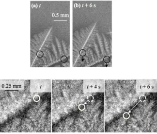
After detachment, the fragments moved upward due to buoyancy (in Al-Cu alloys, the Al-rich solid is less dense than the Cu-rich liquid), and their size de-creased progressively by melting in the hot-liquid region (Fig. 9). For the time being, the X-ray imaging resolution of XRMON-GF (in the 5 − 10µm range) is not sufficient for a direct study of the fragmentation phenomena in proper. In
microgravity experiments, dendritic fragments were detected, but only deeply into the mushy zone (Fig. 10). In that region, the motion of the fragments was drastically reduced, and difficult to image. Surprisingly, dendrite fragments moved, in average, towards the cold region of the sample, that is, in a direc-tion opposite to that observed in 1g experiments. More precisely, the fragments
785
moved along interdendritic channels downward into the mushy zone. This indi-cates that some fluid flow occurs within interdendritic channels, independently of gravity-induced phenomena, most probably due to the solidification-induced shrinkage (density change upon solidification); see [188] and refs. therein. This inward liquid flow could also be at the origin of fragmentation in the deep region
790
of the mushy zone as discussed in Ref. [90]. This shrinkage-induced fluid flow is obviously not gravity dependent, and thus exists even in microgravity condi-tions, as well as in thin samples. Finally, dendrite fragmentation at the top of the mushy zone did not occur in µg, which indicates that buoyancy forces, and remelting mechanisms, were indeed suppressed. This work gives a convincing
795
demonstration of the capabilities of X-ray radiography not only for ground-based research, but also for microgravity experiments. It is also important to stress that, according to those observations, dendrite fragmentation does not occur as a purely diffusive process. It thus differs qualitatively form most of the other solidification pattern formation phenomena presently reviewed, for which
800
both gravity effects (natural convection, buoyancy forces, mechanical forces and hydrostatic pressure) and shrinkage flow can be assumed to have a weak, if not negligible, influence.
4.3. Faceted growth
Faceted growth is observed in intermetallic, ceramic-oxide, semi-conductor,
805
quasi-crystal and many organic (e.g., proteins) systems. At equilibrium, a facet corresponds to a deep, singular minimum (or cusp) in the γ-plot of the solid-liquid interface, and generally aligns with a high-density crystallographic plane. Facet growth occurs by step flow along the interface, and depends critically on the density of active step sources, mostly crystal lattice defects (dislocations)
Figure 9: Sequence of X-ray radiographs showing dendrite-fragmentation events, and the upward motion of dendrite fragments during solidification (vertical sample) under normal (1-g) gravity conditions in the XRMON-GF apparatus (Al-20wt%Cu; G = 15Kmm−1; cooling rate R = −0.15Ks−1). For details see Ref [187].
Figure 10: Top: X-ray radiographs showing the position and the subsequent motion of dendrite fragments (black circles) inside the mushy zone during a µg solidification experiment in the XRMON-GF apparatus (Al-20wt%Cu; G = 15Kmm−1; R = −0.15Ks−1). The time interval between (a) and (b) is 6 s. Bottom: Downward trajectory of a dendrite fragment along an interdendritic liquid channel. Also see Ref. [187].
intersecting the interface [189, 190]. This slow, nonlinear kinetics often leads to very unsteady growth regimes. In some “weakly” faceted systems, however, macroscopic facets present a high mobility even at small undercooling, and grow in a way similar to that of the atomically rough regions of the solid-liquid interface. Steady faceted dendrites have been observed in free growth
815
of pivalic acid [191], and their morphological-selection laws found not to differ qualitatively from that of nonfaceted dendrites [192, 193]. Periodic arrays of faceted cells and dendrites have also been observed in thin samples of impure biphenyl, leading to the same conclusion [194]. Complex faceted patterns such as those observed during bulk solidification of Bi-Sb alloys [195] have not been
820
reproduced so far in transparent alloys, and still remain to be understood. Silicon, as other semiconductors, is also representative of weakly faceted sys-tems. It is an “intermediate” compound in the sense of Jackson’s classification, in that its growth is mostly rough except for one family, namely, {111} planes, of facet orientations. It is worth noting that, due to the shortage of electronic-grade

![Figure 7: Free-dendrite growth. a) Pure xenon (reprinted from Ref. [168], with per- per-mission from EDP Sciences; http://epljournal.edpsciences.org/)](https://thumb-eu.123doks.com/thumbv2/123doknet/14641291.735322/30.918.307.608.272.820/figure-dendrite-growth-reprinted-mission-sciences-epljournal-edpsciences.webp)