HAL Id: hal-02146023
https://hal.archives-ouvertes.fr/hal-02146023
Submitted on 3 Jun 2019
HAL is a multi-disciplinary open access archive for the deposit and dissemination of sci-entific research documents, whether they are pub-lished or not. The documents may come from
L’archive ouverte pluridisciplinaire HAL, est destinée au dépôt et à la diffusion de documents scientifiques de niveau recherche, publiés ou non, émanant des établissements d’enseignement et de
A MODEL-BASED APPROACH FOR DESCRIBING
OFFLINE NAVIGATION OF WEB APPLICATIONS
Félix Albertos Marco, Victor Penichet, José Gallud, Marco Winckler
To cite this version:
Félix Albertos Marco, Victor Penichet, José Gallud, Marco Winckler. A MODEL-BASED
AP-PROACH FOR DESCRIBING OFFLINE NAVIGATION OF WEB APPLICATIONS. Journal of Web Engineering, Rinton Press, 2017. �hal-02146023�
A MODEL-BASED APPROACH FOR DESCRIBING OFFLINE NAVIGATION OF WEB APPLICATIONS
FELIX ALBERTOS-MARCO, VICTOR M.R. PENICHET, JOSE A. GALLUD Computer System Department, University of Castilla-La Mancha, Spain
[felix.albertos, victor.penichet, jose.gallud]@uclm.es MARCO WINCKLER
ICS-IRIT team, Université Paul Sabatier, France [email protected]
Received November 9, 2015 Revised June 23, 2016
The ubiquitousness of the Internet is changing the way users perform their tasks. There is a trend and sometimes a real need to be always connected. The client-server paradigm used in the Web greatly facilitates the consumption of contents. However, there are many situations where the user’s tasks in a Web application might be interrupted due to an unexpected loss of connectivity, temporary unavailability of Web servers, external events, etc., setting the browse to an offline state. The availability of local storage in Web browsers might suggest that users can perform some of their tasks when offline. Nonetheless, several technical constraints might prevent users from efficiently resuming their tasks over the Web after the offline period. In this paper we present a model-based approach called the Offline Model, which is aimed at supporting the execution of tasks interrupted by loss of connectivity based on user navigation with Web applications. Furthermore, we demonstrate how the Offline Model can be exploited to mitigate some of the disruptive effects of interruptions, due to offline navigation, on user tasks based on Web navigation in existent Web applications. The feasibility of such a model approach is demonstrated by a support tool and illustrated by a case study of navigation in a real scenario: the DBLP Web site.
Key words: Interactive Applications, Interruptions, Web, Offline, Model-Based
Communicated by: M. Gaedke & O. Diaz
1 Introduction
Interruptions of users’ tasks over the Web are frequent but very few works have addressed this problem. For example, Tauscher & Greenberg [31] have examined patterns of Web site revisitation and they highlight strategies users employ to bookmark the address of Web sites. Revisitation patterns have been reviewed, following the work of Tauscher, over the last decade, such as in the work of Herder [15]. Indeed, users can rely on bookmarks to recall the addresses of Web sites they have been working on before being interrupted, but this is a minimal solution that does not automatically resume interrupted user tasks. Herder also presents a classification of the main categories of Web activities:
search, work or academic and news are the major categories they found. Among these categories, Albertos presents several scenarios where the need to consider interruptions caused by the loss of connectivity is shown, such as in e-Learning scenarios [21] or in applications with distributed user interfaces[2]. Marco et al. [20] have also argued in a previous work that, if Web applications are meant to ensure continuity of services for the users, developers should not rely on Web technology alone, but design the application to mitigate the effect of interruptions caused by the loss of connectivity.
However, interruptions might affect user tasks in different ways and might be caused by different sorts of events, for example unexpected loss of connectivity (e.g. caused by network failures), temporary unavailability of the Web server (e.g. for maintenance purposes), external events that prompt users to interrupt online tasks (e.g. mandatory turn off of electronic devices during takeoff/landing…), etc.
As a result, and mainly as a consequence of the wide availability of devices supporting Web navigation on the move, users are exposed of been interrupted while navigating the Web. Therefore, users need mechanisms for continuing performing their tasks in offline scenarios. The approach of navigating the Web offline is similar to other scenarios where online tasks are supported in offline environments. An example of these scenarios is the task of listening to music over streaming services, such as Spotify [29] or Apple Music [4]. These applications offer the option of listening to music in a disconnected or offline mode. In a similar way, YouTube Red [44] allows to view streaming videos in disconnected mode. Dropbox [11] also allows to save locally resources for been using when offline. Our approach follows the same idea but dealing with the peculiarities of navigating the Web.
In order to compare interruptions impact, we review the literature in this field and compare it in the light of interrupted work caused by loss of connectivity over the Web. Moreover, in order to overcome the drawbacks of currently available Web technology, we propose a model-based approach for making Web navigation resilient to interruptions. Below we propose a meta-model, referred to as the Offline Model (OM), which is aimed at supporting the design and development of Web navigation that is resilient to interruptions. The rest of the paper is organized as follows. Section 2 presents an overview of interruptions in the context of Web and navigational tasks. Section 3 describes the meta-model for specifying offline navigation. Section 4 describes the process for the generation of the OM in the navigation view as well as the overall architecture and tool support for the execution of the OM. Section 5 presents a case study. Related work is presented in section 6. Finally, section 7 contains the discussion and conclusions of this work, as well as other aspects we are working on for the definition of all the application levels in order to make Web navigation resilient to interruptions.
2 Overview of Interruptions in the Context of the Web
This section presents the main concepts of this work. First, we define how interruptions are viewed in interactive applications, characterizing them according to several factors in order to present the key elements for this work. Then we compare the characteristics of interruptions with respect to the architecture of Web navigation.
2.1 Interruptions in Interactive Applications
There are many definitions for interruptions depending on the discipline [24]. In Human-Computer Interaction, an interruption is often defined as part of the coordination process that requires alternation in multitasking human activity.
Figure 1 Anatomy of an interruption (adapted from Trafton et al. [2.32]).
Based on this definition, figure 1 [33] shows a time line where a task, called the primary task, is interrupted by another task, called the secondary task. Tasks described by Czerwinski et al. [9] (e.g: daily schedule preparation, synch mobile device, check internet email, check and respond to email, matlab coding, create charts for meeting, edit word documents for meeting, …) are an example of complex, long-lasting tasks susceptible of being interrupted. Therefore, a person is working on a primary task. Next, an alert for a secondary task occurs. Alerts come in different forms—for example, a phone ringing, a person coming into the room to ask the person a question, or a fire alarm. During the interruption lag, the person has a moment (or longer) before turning his or her attention to the interrupting task. Then the person starts the secondary task. After the secondary task is completed, the person must resume the primary task. During the resumption lag, the person must figure out what he or she was doing during the primary task and what to do next. Finally, the person resumes the primary task. From this task analysis and the real-world examples, it is clear that different aspects of the cognitive system are relevant to the study of interruptions and resumptions. First, executive control is very important for all interruption/resumption tasks. Second, upon completing the secondary task, the person’s main goal is to remember what task he or she was working on and what to do next (though in some real-world situations, new task demands occur or the environment may have changed so that significant re-planning may need to occur). Third, there may or may not be a link between the primary and secondary tasks. There are also means to aid remembering following these aspects of cognitive systems: people may or may not use some sort of cue in the environment to actively help them remember what they had been doing; and, in some situations (e.g., an emergency), cues may not have been thought about—there may be relatively different preparatory processes that occur. This characterization presents some important aspects worth highlighting: the existence of a task whose execution is stopped to execute another task, and the existence of periods or delays caused by the switch between tasks, known as lags.
McFarlane [24] analyzes interruptions by means of a classification where eight main dimensions for the problem of human interruptions are identified, including the source of the interruption (internal or external to human activity), user characteristics, method of coordination used to handle an interruption (i.e. immediate, negotiate, mediated or scheduled), meaning of the interruption (e.g. reminder, warning, etc), representation of the interruption in the system, channel of conveyance (e.g. visual, auditory, etc.), changes in the activity caused by interruptions and their effects.
Another factor identified by Adamczyk [1] is the moment when the interruption occurs. It may affect user task outcomes. Adamczyk’s results show that it is necessary to identify the moments that are susceptible to being affected by interruptions in order to analyze the best way to deal with interruptions and their effects on the task.
Most of the research on interruptions has been done by conducting empirical studies with users, either under controlled conditions (i.e. usability labs) or in work environments. Current knowledge [32] suggests the following strategies for reducing the disruptive effects of interruptions:
Human training: it has been shown that trained users can recover from interrupted work by rehearsing and/or by learning how to use environmental clues.
Design guidelines may help to produce user interfaces that could reduce the effects of interruptions; for example, specifying where to place visual clues to help users to resume from interrupted tasks.
Specialized tool support, such as GroupBar [9], can help people to save and retrieve applications and window management setups when switching tasks.
2.2 User Interaction with Web Applications
The basic user interaction over the Web implies a request for a Web page and/or a service from a Web server (either by using a bookmark, by clicking on existing links, by typing the URI (Universal Resource Identification) or by using a search engine). If everything works properly, the server responds with the requested information. This kind of information/request communication (as shown in figure 2) between the client and the server is repeated until the users have finished their tasks. In this process, a proxy may act as an intermediary between the client and the Web server. This proxy can provide several functionalities, such us cache proxy or Web proxy, among others. In the browser the users see contents such as an HTML file displayed as a single Web page. Nonetheless, Web pages are quite often a composition of several contents that are stored in individual files on the server side. Indeed, access to the information available on the Web is subject to the inner client-server architecture and the possibility of navigating the information space, which is articulated in three levels [42], as depicted in figure 3. The domain level of the application represents the data model, which is usually managed by a database system or a set of semi-structured documents available on the Web server. The hypertext level represents a non-sequential relationship between the different units of information that make up the application. The presentation level defines the interface with its graphical representation and the distribution of the different elements that constitute it.
It is interesting to note that the local cache on browsers allows the storage on the client side of most recent contents accessed by the users. Therefore, some user interaction with Web contents might occur both with online and offline contents. But it is worthy of mention that currently available cache technologies only store contents with no explicit representation for those tasks users are engaged in.
Figure 2 Overview of interaction flow between the user and Web applications through the Web browser, local cache, proxy and the Web server.
Figure 4 Web application levels in online and offline scenarios.
To illustrate how interruptions affect Web applications, figure 4 depicts the main levels in Web applications, presented in figure 3, and their characterization in online and offline scenarios. This characterization explains why elements at each level of the Web application may not be available during the connection interruption, when the site is offline. For example, at the hypertext level, it can be shown that when the site is online, all the nodes or Web pages are available, allowing normal navigation between them through the hypertext links available in the application. This is because the data structures that support those information units, described in the domain level of the application, are available. It should be noted that the mapping between levels, navigation mapping in this case, establishes the association between the elements at the domain level with the hypertext level. Similarly, through the mapping between levels, each element at the presentation level is available for each element at the hypertext level.
However, in the offline scenario depicted in figure 4, it can be seen that there are elements that are unavailable in some levels. These are depicted in grey and in an attenuated form. At the hypertext level there are non-available nodes because during the interruption some of the elements at the domain level of the application are not available for the Web application. In the same way, and according to the mapping between the corresponding levels, there are elements at the presentation level that cannot be visualized, either partially or totally. That means that there will be Web pages that, in the presence of interruptions, can be navigated normally, but others that cannot be navigated at all, while other Web pages which can only be navigated partially.
Available elements will depend on several factors. Due to the complexity of Web applications and the diverse nature of the tasks that can be performed, we cannot leave to chance the available elements. Moreover, the availability or unavailability of those elements would depend on the requirements identified by the software engineers or Web site designers. However, in certain situations, the particular execution for each instance for the task performed by users through the Web browser would also have to be taken into account, and the actions performed by these users.
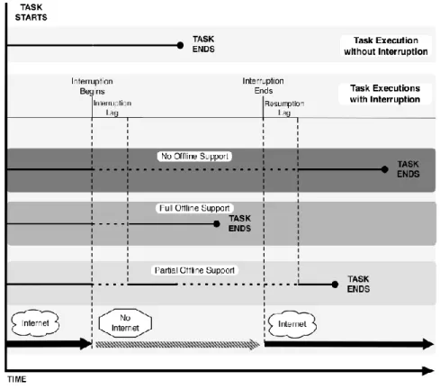
Figure 5 Offline support in interactive tasks.
2.3 Interruptions and the Execution of User Tasks in Web Applications
An analysis of the offline support for interactive tasks, as seen figure 5, shows how a task is executed with, and without, interruptions. When the task is executed without interruptions, the user can perform the task continuously; the task can be executed without any breaks or stops. On the other hand, when the task is performed with interruptions, this affects the way it is carried out. It has to be considered that there are two periods during the interruption, called interruption lag and resumption lag. These periods are located at the beginning and at the end of the interruption, respectively. During these lags, tasks are susceptible to being suspended. Consequently, considering that the abscissa in figure 5 represents the time from when the task starts, tasks affected by interruptions will take longer depending on the lags that affect them.
Support Characteristics
Group 1: None
The task cannot continue its normal execution due to the interruption. While the interruption occurs, the task is suspended, continuing with the execution once the interruption ends.
Group 2: Full
The task can continue its normal execution during the interruption. It is not affected by it.
Group 3: Partial
The task can continue the execution during the interruption, but only partially. As a result, part of the execution takes place during the interruption and the other part is executed once the
interruption ends.
Table 1 Offline support groups in Web applications.
A task may belong to one of the three groups presented above (table 1) depending on different circumstances. This classification does not only depend on the task itself. There are several factors that influence the task execution during the interruption, especially the availability of necessary resources to perform all the stages of the task. As a result, some tasks may belong to different groups depending on that availability. There will be tasks that, given their nature, belong to Group 1. Other tasks, however, could belong to any of the three groups depending on the scenario. Depending on the available elements on each of the Web application levels, when the interruption occurs the task that is being executed will or will not be able to be performed. As a result, for a Web application, based on the available elements in each of the three levels and its mapping functions, the offline groups’ support may vary depending on the particular execution.
2.4 Aspects Affecting Navigational Tasks of Web Sites
In view of the set of main categories in Web activities [15] and the analysis made on interruptions and the execution of user tasks in Web applications, user tasks over the Web will reveal that the disruptive effect of interruptions depends on several aspects, including:
• Availability of contents when online or offline. Contents such as video streaming are only accessible online, but other types of contents (such as html pages and images) can be stored in the local cache. The availability of contents is thus determinant to know whether (or not) users can pursue their tasks.
• How the browser informs users about changes in connection modes. To decide if they can carry on with tasks users must know which contents are available. Visual clues provided by changes in the Web page can help users to determine if they can navigate contents in the local cache and/or access the necessary contents.
• Actions undertaken to mitigate effects of interruptions. Before an interruption caused by loss of connectivity occurs, it is possible to download contents related to the user’s tasks in case they could be useful in the future, so that if users get disconnected, they can pursue their tasks using contents previously downloaded by the browser. Restoring the state where users left tasks can help them to complete interrupted work.
Also, we can summarize that the activities carried out involve Creating, Retrieving and Updating or Deleting information on the Web. When dealing with interruptions we can establish two groups depending on the implications when the task is interrupted:
• Group Storage: when retrieving information from the Web it has to be stored in order to be available when the task is interrupted. It does not need to synchronize user interaction with
the system after the interruption. This group uses mainly two mechanisms to retrieve information:
o Through the URI, as the core of the hypertext information systems. It uses mainly static pages.
o Entering queries to interact with service-oriented interactive systems. This approach uses mainly forms to interact with users.
• Group Update: Create, Update or Delete information on the Web. When one of these actions is taken when the task is interrupted, user interaction has to be stored in order to be updated when the task is resumed.
These aspects and groups are at the core of strategies for developing tools for dealing with interrupted work on the Web.
3 A Meta-Model for Specifying Offline Navigation
In this section, we present a model-based approach called the Offline Model (OM), which is aimed at supporting the analysis of interrupted tasks based on user navigation with Web applications. This model provides mechanisms to describe states and operations that users can perform when the interruption begins and ends. It also provides adequate mechanisms so that users can keep performing their tasks in the presence of interruptions.
We start by presenting the meta-model that contains all the concepts necessary to understand the behaviour of Web application in online and offline connection modes. This meta-model enables the instantiation of different models for the description of layers that make up Web applications: hypertext and presentation.
For the presentation layer, the meta-model uses conceptual elements extracted from USIXML [19]. USIXML is a markup language based on XML that describes the user interface from various perspectives. It uses four abstraction levels as a framework for the development of user interfaces: tasks & concepts, abstract UI (AUI), specific UI (CUI) and final UI. When it comes to describing the user abstract UI, USIXML provides abstract interaction objects, in which four main facets have been identified: Input, Output, Navigation and Control. These facets will be used in offline meta-models as constructors for the characterization of the elements in the presentation level.
3.1 Overview of the Offline Meta-Model
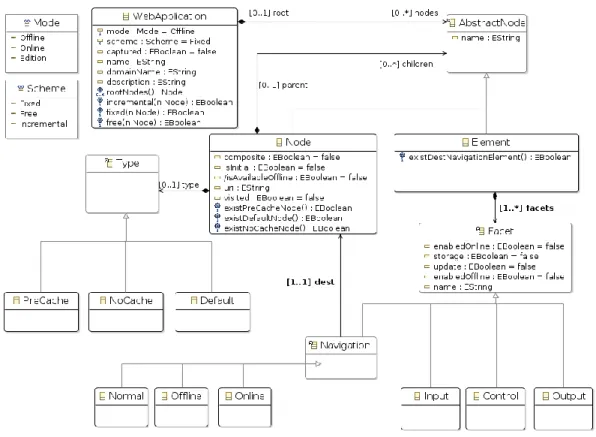
The offline meta-model is depicted in figure 6. The concepts represented in it are the foundations for the description of the navigation in Web applications in the presence of interruptions. These concepts are introduced below.
3.1.1 WebApplication
The root element in the model is called the WebApplication and it has the information to characterize the Web site that is represented. This information contains: domain name, name and description. With this information the Web site is unequivocally identified. It also contains the boolean attribute named
“captured”. It indicates if the Web Application has been processed and the site has been captured to be available when the Web application is in Offline Mode.
3.1.2 Mode
The attribute mode is of the type Mode, which is an enumeration. It represents the states of the OM in each phase of the interruption. The OM Mode has three values: online, offline and edition. The first two values are directly related to the interruptions occurring during task execution. Therefore, the OM Mode is offline when the task is between the beginning and the end of the interruption, and online the rest of the time. The edition mode represents the status when the model is being edited. It is used in edition tools.
Figure 6 Offline meta-model.
3.1.3 Scheme
We have identified three schemes for Web sites that characterize the offline behaviour of Web applications: Fixed, Free and Incremental. These schemes enable us to classify Web sites when designing the Web application levels, according to the availability of the corresponding elements. In the Fixed scheme, available elements are set in design time. These elements are independent of further decisions or actions made by users. In the Free scheme, available elements completely depend on decisions or actions made by users during the execution of the Web application. In this scheme, there
is no fixed set of available elements before the Web application execution. Finally, the Incremental scheme is a mix between the previous schemes, Fixed and Free. In the Incremental scheme there is a fixed set of available elements, but user actions and decisions may add or remove elements from other sets of variable elements, such as the Free scheme. The main characteristics of these schemes are shown in table 2.
Schema Available elements Initial elements Does it take into account user actions?
Fixed Fixed Yes No
Free Variable No Yes
Incremental Fixed + Variable Yes Yes
Table 2 Schemes for the characterization of offline Web applications.
3.1.4 Abstract Node
The Abstract node is a Composite pattern in which two kinds of elements are used: Nodes and Elements (see below).
3.1.5 Node
The Abstract Node enables the definition of the relationship between related entities. One of the main characteristics in Web applications is that they allow navigation between a type of their elements called Web pages. Consequently, when designing the OM we define a Node as a Web page within the Web application. The information needed to characterize a Node in the OM is its URI and a Name. The name is needed to identify the Node within the OM.
The Composite attribute indicates if the node represents a composite node. When it is set to true, it supports the creation of composite nodes within the model. A composite node contains nodes which share a navigational structure. Nodes contained in a composite node inherit relationships from their parents. They are used to improve models readability. In some cases, e.g. due to space constraints, only the composite node is detailed in the model although the contained set of nodes could be expanded.
At the same time, a node is defined with a type with the following values: NoCache, PreCache and Default. Therefore, the OM allows the definition of Node availability or unavailability during OM execution. As a result, we can establish that: a NoCache Node will never be available in the Offline Mode; a PreCache Node will always be available in Offline Mode; and a Default Node will be available in Offline Mode depending on the execution of the OM, for instance, when the user performs some actions or takes decisions.
Within the set of Nodes, it is mandatory that a node with the Initial attribute set to true exists in the entire Web site as well as for each composite node. Initial nodes are considered the entry or starting point within the model at two levels: the entire Web site level (for the high level node) and composite level (for nodes within a composite). This constraint is detailed in section 3.3.
Navigation between nodes is defined in the OM by means of the Navigation class. This class enables navigation between nodes. It allows classification of navigation depending on the navigation type and the OM Mode. As a result, Normal navigation allows navigation between nodes regardless of
the mode. On the other hand, Online and Offline navigation only enable navigation between nodes in the homonymous OM mode.
It is worth pointing out that node type and Navigation class are founded on the first aspect we have detected that affects navigational tasks of Web sites: the availability of contents when the user is online or offline.
3.1.6 Element
The abstract Node may also contain components of the Element type. These components describe elements within a Node. As a restriction, an Element cannot be directly inside an Abstract Node; it will always be inside a Node.
Each Element has one or more facets. These facets identify particular functions that the element may carry out in the physical world. In the OM 4 facets that have been previously described in UsiXML [19] are defined: Input, Output, Control and Navigation. Each facet is described as follows:
• Input facet: the element accepts user inputs. • Output facet: the element offers outputs for users. • Control facet: the element performs system functions.
• Navigational facet: the element activates a transition between Nodes.
At the same time, each facet is characterized by four attributes that typify the described element. They are described as follows:
• EnabledOnline: it specifies if the element is enabled or if it allows interaction with users when the OM is in Online Mode.
• EnabledOffline: it specifies if the element is enabled or if it allows interaction with users when the OM is in Offline Mode.
• Storage: the element requires local storage to be used when the OM is in Offline Mode. It is used when the element is a resource that is not directly included in the Node it belongs to and it is not a node. For example, a linked PDF document. This attribute is related with the group storage presented in Section 2.4.
• Update: it defines an element that requires interaction when the OM is in Offline Mode, and also requires updating the Web application when the interruption ends, that is, when the OM returns to the Online Mode. This attribute is related with the group update presented in Section 2.4.
3.2 Model’s Navigation View
Within the OM, we can classify Web application elements according to the level they belong to (table 3). Nodes in the OM are in the hypertext level because they describe information units that make up the application and their relationships. Elements in the OM are classified according to their facets. Therefore, Input, Output and Control facets belong to the presentation level. The Navigation facet belongs to the hypertext and presentation level. This is because this facet modifies the behaviour of
both levels, since both navigation between elements of the model and the representation of the interface are affected.
Element\Level Hypertext Presentation
Node X
Input Facet X
Output Facet X
Control Facet X
Navigation Facet X X
Table 3 Characterization of the OM elements according to modelling levels.
OM Component Description Representation
Node Represents a node within the model. It includes the name of
the node in the upper-left side of the node
Initial Nodes with this icon are initial nodes
NoCache Nodes with this icon are of type NoCache
PreCache Nodes with this icon are of type PreCache
Default Nodes with this icon are of type Default
Cached Nodes with this icon have the attribute isAvailableOffline
set to true
Visited Nodes with this icon have the attribute Visited set to true,
meaning the user has visited the node
Current The node with this icon is been currently visited by the user
Visitable The node with this icon could be visited from the current
node
Navigation enabled online/offline
Navigation between the nodes connected with this arrow, in the arrow’s direction, is enable in both modes: online and
offline
Navigation enabled only online
Navigation between the nodes connected with this arrow (in the arrow’s direction) is enable only in online mode
Navigation enabled only offline
Navigation between the nodes connected with this arrow (in the arrow’s direction) is enable only in offline mode Table 4 Graphic notation for the hypertext view in the OM.
In the hypertext view, nodes, their characteristics and the relations between them are represented. For this representation, we use the notation depicted in table 4. This language enables us to graphically represent the concepts presented in the meta-model for the definition of models in line with our OM.
3.3 Restriction Representation in the OM with Ecore / OCL
There are restrictions that cannot be represented directly in the presented OM. That is the case, for example, of the requirement to always have an initial state in the OM, or that every element needs to have a parent node. As a consequence, we have enriched the meta-model with invariants defined in OCL to formally express all the restrictions of the OM. These invariants are presented as follows:
IncrementalScheme: this invariant establishes whether the OM scheme is incremental. That implies
the existence of a PreCache Node and the absence of a Default Node. The OCL expression for this invariant is shown below.
Context OfflineModel invariant IncrementalScheme:
scheme = Scheme::Incremental implies Node.existPreCacheNode() and Node.existDefaultNode();
FixedScheme: this invariant establishes whether the OM scheme is Fixed. That implies the existence
of a PreCache node and the absence of a Default Node. The OCL expression for this invariant is shown below.
Context OfflineModel invariant FixedScheme:
scheme = Scheme::Fixed implies ((Node.existPreCacheNode() or Node.isInitial) and not Node.existDefaultNode());
FreeScheme: this invariant establishes whether the OM scheme is Free. That implies the absence of a
PreCache Node and the existence of a Default Node. The OCL expression for this invariant is shown below.
Context OfflineModel invariant FreeScheme:
scheme = Scheme::Free implies not Node.existPreCacheNode() and Node.existDefaultNode();
NotNavigationElement: this invariant prevents a node from always having a navigational Element.
The OCS expression for this invariant is shown below. Context Node invariant NotNavigationElement: self.children->exists(oclIsTypeOf(offlinemodel::Element)) and ( self.children->collect(oclAsType(offlinemodel::Element)).facets-> exists(oclIsTypeOf(offlinemodel::Normal)) or self.children->collect(oclAsType(offlinemodel::Element)).facets-> exists(oclIsTypeOf(offlinemodel::Online)) or self.children->collect(oclAsType(offlinemodel::Element)).facets-> exists(oclIsTypeOf(offlinemodel::Offline)));
ForceParentNode: this invariant prevents an element from always having a parent Node. The OCL
expression for this invariant is shown below. Context Node
invariant ForceParentNode:
not self.parent.oclIsUndefined();
NotConnectedPage: this invariant prevents a node from always having a valid connection with other
node/s. The OCL expression for this invariant is shown below. Context Node
invariant NotConnectedPage:
OnlyOneRoot: this invariant prevents the creation of more than one initial node at high level. The
OCL expression for this invariant is shown below. Context WebApplication
invariant OnlyOneRoot:
self.rootNodes()->select(oclIsTypeOf(Node))->collect(oclAsType(Node))->select(isInitial)->size()=1;
OnlyOneComposite: this invariant prevents the creation of more than one initial node in composite
level model. The OCL expression for this invariant is shown below. Context Node
invariant OnlyOneComposite:
self.children->select(oclIsTypeOf(Node))->select(composite)->select(isInitial)->size()<2;
3.4 Some OM Properties
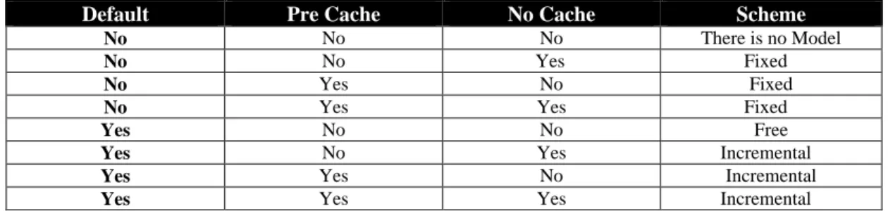
The scheme can be defined according to the Nodes that it comprises. Therefore, the Fixed Scheme is defined as follows: an OM follows a Fixed Scheme if there is at least one PreCache Node, and there is no Default Node. This scheme describes an OM where available Nodes for user interaction in Offline Mode are always the same during the whole execution of the OM. The Incremental Scheme is defined as an OM where there is at least one PreCache Node and also a Default Node. An OM with this scheme has a variable number of available Nodes during the execution of the OM. That number will vary according to the user interaction with the site, and it will be always greater or equal to the number of PreCache Nodes. Finally, an OM follows the Free Scheme if there is no Precache Node and there is at least one Default Node. These OMs have at least one Node that will be available in Offline Mode, the initial node, and the number of available nodes in Offline Mode will be limited to the number of nodes included in the OM.
Table 5 shows the possible combination of values that define the scheme according to the existence or absence of the different types of Nodes in the OM.
Default Pre Cache No Cache Scheme
No No No There is no Model
No No Yes Fixed
No Yes No Fixed
No Yes Yes Fixed
Yes No No Free
Yes No Yes Incremental
Yes Yes No Incremental
Yes Yes Yes Incremental
Table 5 Scheme characterization according to the node types of the OM.
4 OM Generation Process: Navigation View
The main function of Web applications is to enable users to execute their tasks. Therefore, to generate the navigation view of the OM we start from a task model. Once the task model has been produced, the next step is to transform that model into our OM. To do this, we have decided to use an existent navigational model: SWC [42]. It is worth noting that the OM is not limited to extending SWC. It could be used to extend other navigational models thanks to the fact that the OM meta-model has common elements to describe navigation on Web applications. To generate the OM from another
navigational model it is only necessary to define the transformation process, as was the case for the SWC model transformation process.
The decision to extend SWC is based upon the following facts:
• It allows the use of an existent navigational model with a formal base.
• There is an existent method to transform a task model (CTT [25]), into the navigational model (SWC) [43].
• It allows the generalization of the transformation process, opening up the possibility of extending other existent navigational models, as well as other task models. Therefore, other navigational models will be able to use our OM.
Consequently, the creation process of the OM navigation view is as follows:
• The first artefact is the task model. It expresses task requirements according to user intentions.
• The task model is transformed into a navigational model: in this case SWC. • Transformation of the navigational model into the OM.
Once the transformation process from the task model to SWC has been defined, as we have already seen, we only need to define the process for the transformation from the navigational model (SWC) into the OM. That process is divided into two steps:
1. Defining the mapping function between SWC concepts and the OM. 2. Defining the method to perform the transformation between the two models.
The actors involved in the transformation and/or generation process of the OM depend on the stage of the process model. They have to be set in order to fulfill the requirements or goals of the Web application.
4.1 Mapping Function Between SWC and the OM
The first step is the definition of a mapping function between the concepts of the OM’s meta-model and the navigation model, SWC. Consequently, the meta-model’s Nodes correspond to the states in SWC. Transitions in SWC correspond to the Navigation Facet in the meta-model. Thus, a mapping function, as presented in Tables 6, 7, 8, 9 and 10, that makes it possible to establish a correspondence between the two models can be established so that, ultimately, we can transform an SWC model into an OM. In our proposal this process is manually performed.
At this point, it is worth highlighting that both SWC and the corresponding OM are conceptual models that allow the designing of user tasks for Web applications in the hypertext level. However, given the nature of Web applications and the OM, a second OM, called the Execution Offline Model (EOM), has been defined. The reason for this is the existence of states or dynamic nodes whose results depend on every instance of the Model. Therefore, conceptual models show the static design of the Web. The execution model shows the interaction between the user and the Web application that, along with the conceptual design, will establish the state for each specific execution of the model.
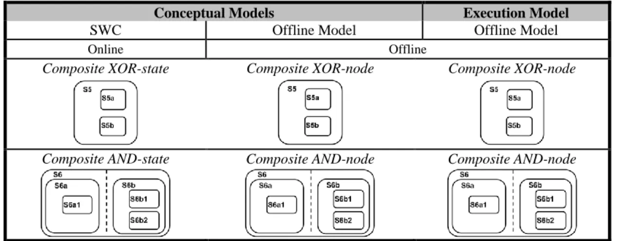
In the following tables we present the transformations between the elements of the conceptual SWC, the conceptual OM and the execution OM. Table 6 presents the transformation for the static, transient and dynamic states in the SWC model with their correspondent OM elements.
Conceptual Models Execution Model
SWC Offline Model Offline Model
Online Offline
Static state Static node Static node
Default PreCache NoCache Visited Current Transient state - -
Dynamic state Dynamic node Static node
As many nodes as produced during the execution
Table 6 Transformations between SWC and the OM: Static, Transient and Dynamic states.
Table 7 presents the transformation for the external and initial states in the SWC model with their correspondent OM elements.
Conceptual Models Execution Model
SWC Offline Model Offline Model
Online Offline
External state External node - Initial Initial
Table 8 represents the transformations for the composite states in the SWC model with their correspondent OM elements.
Conceptual Models Execution Model
SWC Offline Model Offline Model
Online Offline
Composite XOR-state Composite XOR-node Composite XOR-node
Composite AND-state Composite AND-node Composite AND-node
Table 8 Transformations between SWC and the OM: Composite states.
Table 9 presents the transformation for the special states in the SWC model with their correspondent OM elements.
Conceptual Models Execution Model
SWC Offline Model Offline Model
Online Offline
Shallow history state History
Last visited page becomes the current page
Deep history state
- -
End state Delete Model on Runtime
Table 9. Transformations between SWC and the OM: special states.
Finally, table 10 presents the transformation for the transitions in the SWC model with their correspondent OM elements.
4.2 Transformation Method Between SWC and the OM
In order to carry out the transformations between SWC and the OM models, two phases have been defined. In the first phase, the SWC conceptual model is transformed into the OM. For this stage, five steps are defined:
• Step 1: OM node generation and their transitions: composite states (XOR and AND) and static states remain unchanged. Dynamic states are transformed into the OM Dynamic
Nodes. User and Realization transitions remain unchanged among the existing nodes. Initial states remain unchanged.
• Step 2: Temporary state elimination: temporary states are deleted, maintaining existent transitions and their initial states.
• Step 3: Transition adjustment on deleted states: execution and user transitions that have dynamic or static states as a source, and the deleted temporary state as a target, are completed with the transitions of systems that have these states as a source, and the corresponding static/dynamic nodes as a target. Once the process has been performed, if a transition does not have a target, it is deleted from the model.
• Step 4: Initial node adjustment: initial nodes that belong to deleted states are moved from the deleted states to the static/dynamic nodes. To carry out this process, the transition directions created in the previous steps are followed. The transitions without source and/or destiny are also deleted. The labels for the existing transitions remain.
• Step 5: OM decoration with the attributes that characterize offline navigation: the elements that describe how the Web application is going to behave in the presence of interruptions are inserted in the OM. This step fully depends on designer decisions. The characterization allows the OM to support user tasks in the Web site. The behaviour will be different according designer’s decisions on this step. Available nodes (Web pages), elements, as well as connections, for offline use are decided here. The process consists on the decoration of the model with the elements presented in the tables of the previous section.
Conceptual Models Execution Model
SWC Offline Model Offline Model
Online Offline
User transition
Completion transition Connection Connection
Normal
Offline
Online
System transition
- -
User defined label or stereotype
<<Stereotype name>> <<Stereotype name>> <<Stereotype name>>
The second phase corresponds to the transformation of the conceptual OM into the execution OM. Four steps for this transformation have been defined:
• Step 1: For each visit to a dynamic node, a static node is generated.
• Step 2: This node inherits attributes from the dynamic node, with the exception of the initial attribute. The initial attribute is only inherited by the first generated node from the dynamic node.
• Step 3: Each generated static node has the same transitions as the dynamic node that generated it.
• Step 4: For each static generated node, the reflexive connections that have the same state as a source and target are transformed into connections to all the nodes generated from the source dynamic node.
4.3 Availability of Nodes and Elements in the EOM
The availability of nodes at runtime is determined depending of the type of node and the value of the attribute “Captured” within the OM. This attribute is set to true when the Web site has been saved for offline use. Table 11 represents the availability of nodes.
Site Captured Node Type
NoCache PreCache Default
False Not Available Offline Not Available Offline Not Available Offline
True Not Available Offline Available Offline Depends on User Actions
Table 11 Availability of nodes at runtime within the EOM when offline.
As can be seen in table 11, the node will be available offline when the node is of type “PreCache” and the site has been captured. When the node is of type “Default”, the availability of nodes depends on specific user actions over the nodes (Web pages). These actions could be implicit or explicit, depending of the concrete implementation of the tool support for the EOM.
Another attribute to take into account is the attribute “isInitial”. When the node is set to Initial (isInitial=true), from the point of view of node availability, it behaves in the same way as if it were of type “PreCache”.
The process of determining the availability of elements is similar as for nodes, but taking into account the facets of the element. An element will be available online/offline if the attribute EnabledOnline/EnabledOffline is set to true. Also, in offline mode the attribute “Captured” has to be taken into account for the Element availability (as for the case of nodes).
4.4 Overall Architecture and Tool Support for Offline Model Execution
To validate the proposal, a support tool that allows OM execution has been developed. As a result, the theoretical proposal is implemented, verifying if it is working according to the design of the OM.
The tool is mainly composed by two pieces of software: the Offline Proxy (OP) that is in charge of injecting the OM and the Offline Engine (OE) in the original Web application and the Offline Engine.
The figure 7 depicts the process of a client requesting a Web page and how the OM and the OE is injected in the original Web application by the OP.
Figure 7 Overview of the interaction flow between the user and Web applications using the Offline Proxy.
The OP is a piece of software located between the client and the Web server. It is a proxy that captures each client’s request to the Web server and sends a modified answer. This answer supports the OM in the client. The OP forwards the request from the client to the Web server and receives the answer from it. The answer contains the original HTML code and the resources of the Web application requested by the client.
At this point the Offline Proxy is in charge of two tasks: modify the original HTML code according to the OM and the injection of the OE in the answer. The modification of the original HTML code follows the design of the OM. It is in charge of the enrichment of DOM elements and the inclusion of the OE library. This process includes the OM in the original Web application.
The OE is a JavaScript and CSS library that is in charge of translating the conceptual OM into the Execution OM (EOM) for each execution of the Web application in the Client. It is also in charge of determining the availability of Nodes and Elements in the EOM. This process is automated and there is no need for manual intervention. The OE is located in the OP, but it is injected in the Web application for each request. The OE is loaded in the browser during the execution of the Web application on the client side. It is in charge of making the operations so that the Web application behaves according to the conceptual OM injected in the DOM by the OP for the Web application. To this end, the OE
modifies the Web application levels and is in charge of managing the browser’s local cache to allow offline support.The operations the OE performs in the Web application depend on three factors:
• Connection status: online and offline. • Conceptual OM design.
• User actions over the Web application: navigation and decisions made over the OM.
As mentioned in the previous section, the process of saving the Web for offline use and user actions over nodes depends on the concrete implementation of the tool support. For saving the Web for offline use there are many strategies: saving the Web site only the first time the user visits it, each time the user loads a Web page or on demand through explicit user actions (e.g. pressing a button on the Web application). User actions over nodes may also have different strategies, such as set each visited paged as available for offline use or on demand through explicit user actions.
From the technologically point of view, we have used several technologies to support the functionality of the OM on this tool. In the server side, the OP has been implemented in PHP. In client side, the OE has been implemented in JavaScript and CSS. We use the jQuery library to hide/show elements and to enable/disable user interactions with them. To provide offline interaction we use HTML5 technologies: Offline Web Applications [34], Web storage [37] and File Api [41].
It is worthy of mention that in this section is presented an overview of the tool support. A complete description of the support tool, transformations on each Web application level and a complete analysis of how user actions over the Web application are managed will be presented in future work.
5 Case Study
Now that the OM and the process for its generation have been presented, we illustrate the process with a specific case study. Since, according to the process described above, the starting point is the user task to generate the OM, first the task is presented. The task consists of searching for information on the DBLP Web site [10]. Thus, once the task has been modelled by using the relevant transformations, the corresponding navigation and OM models will be obtained. For this case study the Web master is in charge of designing the task model, as well as generating the OM through the transformations defined previously. Other actors involved are the end users, who will generate the EOM for each execution over the Web application.
But before presenting the case study it is important to understand how the conceptual design of the OM affects the visualization of offline contents. Therefore, in the next chapter the visualization of offline contents is illustrated in a simple Web site.
5.1 Visualization of Offline Contents
During OM execution there are transformations in the visualization of offline content that depend on the conceptual design of the OM. The design of the transformations over the visualization is beyond the scope of this work, but the mechanisms used for the visualization of offline content are presented. Next, we describe a simple scenario in which the OM has been used to modify the visualization for offline contents.
The scenario to illustrate page layout transformations can be seen in figure 8. There, a Web application that uses video streaming is depicted. When the Web application is in online mode, the video is made visible to the user (highlighted with a dotted red line). But when the Web application is in offline mode, the video streaming is hidden. In the figure 8, within the offline mode (right) can be seen at the bottom of the image a blue arrow indicating that the offline information tool is available. This tool shows information about the transformations made on the Web application as well as available Web pages in offline mode.
Figure 8 Offline content transformations: page layout with video element.
Figure 9 Offline information tool: removed elements and offline navigation map.
Transformations in visualization when offline allow users to focus on the actions that can be carried out within the offline task. In the figure 9 can be seen how when the user activates the offline information tool can be seen two new elements overlapped to the Web application: 1) Removed
Elements: textual information about removed elements from the user interface; 2) Offline Navigation Map: graphical information is provided depicting a navigation map for the offline Web application.
5.2 Task: Searching for Publications on DBLP Web Site
The case study task consists of searching for publications by the authors that belong to a specific paper. This scenario is much more complicated than the one presented before and shows how the OE can be used in a wide range of Web applications.
DBLP is an online computer science bibliographic reference server that allows searching for publications by authors. It enables searching by the name of the author and types of publications, as well as navigating through related authors. To perform the task of the case study, it is necessary to know the title of the paper and the name of its first author. The main goal of the task is to know all the publications by the author and the name of the co-authors of that paper. In order to perform this task, the user has to take several steps, as described below.
First, the user goes to the main page of the DBLP site. Once there, the user introduces the name of the first author of the paper in the search box. The user sends the query to execute the search. The system returns the search results with the author's publications. Among these publications, the user can find the paper he or she was looking for. Next, the user collects the author information and browses the co-authors’ pages. For each author, the user repeats the same procedure until he or she has visited all the pages related to the author of the selected paper. In addition, the DBLP site allows navigation through other types of publications. This task is represented in figure 10 using CTT [25].
Figure 10 Case study task: searching for authors on DBLP site.
The described task may belong to more than one of the offline support groups introduced in previous sections. For example, if it is performed in a scenario without any kind of offline interaction support, it will belong to the group with no offline support. This is because once the interruption occurs, the user cannot continue with the task. The user has to wait until the interruption ends to continue performing the task. In the same way, if the task is performed within a scenario that uses offline interaction with the Web site (for example, using the browser to locally save information
related to all the authors that belong to the publication the user is looking up), then the user will be able to complete the task even if there is an interruption. In this case, the task belongs to the full offline support group.
5.3 Interruption Characterization
The presented task is exposed to interruptions that may affect its performance. To achieve navigation that is resilient to interruptions during task execution, firstly the key factors to design the OM have to be identified.
One of the key points that has to be identified is the moment when the interruption occurs, as we have seen in previous sections. It is noteworthy that in our case study there are several critical points that could be affected by interruptions. These occur when there is an interaction with the server. As a result, they have to be identified in order to manage them properly when designing the OM, as depicted in figure 11, where critical points are inside a gray square.
Figure 11 Searching for authors on DBLP site: critical points.
It can be seen that these critical points correspond to user interaction with the Web server. Therefore, the information resulting from this interaction has to be properly taken into account to manage these states in a proper way. In this case, we chose a mechanism that allows the system to make this information available once the interruption occurs. Then, the user will be able to keep interacting with the site and perform the task normally.
Regarding the dimensions that characterize interruptions and that have been presented in previous sections as important for designing our OM, here is a list of all of them:
• Source of the interruption: the source of the interruption is the loss of connectivity with the DBLP platform.
• Individual characteristics of the person: the use of the platform is not limited to specific users. Only a basic knowledge of navigating using a Web browser is needed. Therefore, any user who is able to browse the Web site without interruptions has to be able to browse it with interruptions.
• Coordination methods: interruptions supported by the OM are both the expected and the unexpected.
• Impact of the interruption: users have to be able to continue performing the task during the interruption in order to navigate through previous searches and visits made before the interruption.
Once the interruption has been characterized, the next step for the generation of the OM is the generation of the navigation model. As we have already seen, the SWC model will be used.
5.4 Navigation Model: SWC
Based on the task model, we performed the transformation into the SWC model. Special attention has to be paid to server tasks, as depicted in figure 11. These tasks are transformed into temporary states in the SWC model. The tasks that produce results that are previously unknown, for example author pages that are going to be visited by the user, are represented by means of dynamic states. The other states represent pages that are visited by the user during the task. The existent transition between the states is also represented. In figure 12, the resulting SWC model for the task of searching for authors on the DBLP platform is depicted.
Figure 12 SWC model for the case study.
Based on the SWC model, we define the required transformations to obtain the corresponding OM.
5.5 Conceptual OM Generation
The following is a description of the five steps required to transform the SWC model for this case study into the OM. To illustrate the transformation process a set of figures is included. In these figures, the SWC model elements are shown in an attenuated form. On the other hand, the OM elements produced are shown in a regular way.
Step 1: Generation of OM nodes and their transitions. In this step, the static and dynamic nodes from the homonymous SWC states are generated. As a result, the static nodes labeled “DBLP home” and “About” are generated. The composite states labeled “Navigation”, “Query by Author” and “Browse” are also generated. Dynamic states are transformed into dynamic nodes, obtaining as a result the dynamic nodes “List of publications” and “list of items in category”. User transitions are transformed into connections. The resulting model for this step is depicted in figure 13.
Figure 13 Step 1 of the transformation SWC- OM for the case study.
Step 2: Temporary state elimination. Temporary states are deleted, keeping existing transitions between them and initial states in order to operate with them later. Temporary states are depicted with dashed borders. The resulting model for this step is depicted in figure 14.
Figure 14 Step 2 of the transformation SWC- OM for the case study.
Step 3: Transition adjustment on deleted states. Transitions whose target is a deleted temporary state are joined to the transitions whose source is the deleted temporary state. In this way, transitions are joined, producing a unique transition. This is the case of the outgoing transitions of the node “List of publications” or “List of items in category”. The resulting model for this step is depicted in figure 15.
Figure 15 Step 3 of the transformation SWC- OM for the case study.
Step 4: Initial node adjustment. Initial states are moved, when necessary, from the deleted temporary states in the Step 2, following the direction of the existing transitions between states. In this way, the nodes “List of publications” and “List of items in category” become initial states. Figure 15 shows how these initial states belonged to deleted states and, following the corresponding direction, become part of the corresponding node. The resulting model for this step is depicted in figure 16.
Figure 16 Step 4 of the transformation SWC- OM for the case study.
Step 5: OM decoration with the attributes that characterize offline navigation. For this case study, the attribute precache is added to the dynamic states of the model. This step depends on the scheme the designer wants the model to follow, as well as the relevant decisions made for the behaviour of the OM according to its elements. The resulting model for this step is depicted in figure 17.
5.6 Generation of the Execution OM
Based on the conceptual OM, the specific instances according to user navigation from the OM generated in the previous phase are generated. These instances correspond to the execution OM. The transformation between elements on both models is described in tables 6, 7, 8, 9 and 10.
Once the transformation to the execution model has been performed, the peculiarity comes from the dynamic states. A priori, produced states are unknown. They depend on the specific execution of
the model. In order to carry out the transformation between the conceptual OM and the execution OM, we consider that the user performs the following operations on the DBLP platform: the user visits the following pages: authors FAM, JAG, VP and MW. The user also visits the following categories: Conferences, Journals and Series.
Figure 17 Conceptual OM for the case study.
Based on the transformation rules between the conceptual OM and the execution OM with the instance described above, the execution OM depicted in figure 18 is produced. There we can see how dynamic nodes have been transformed into as many static nodes as there are executions performed over them. Furthermore, these static nodes have inherited the attributes from the dynamic node. In this case, all of them have inherited the ‘precache’ attribute. However, only the first generated static node has inherited the ‘initial’ state.
Figure 18 Execution OM for an instance of the case study.
With the execution model, the process for the generation of the OM described in the above sections has been completed. Thus, all the phases and steps to follow in a real case study have been illustrated, proving its feasibility: from a task model, a navigation model that has been transformed into the OM has been generated.
5.7 Execution of the Offline Model Described in the Case Study
In our case study using the DBLP site, transformations make links for publication details and parts of the Web application that are available or unavailable. To do this, the OE performs two operations:
• When the Web application is in online mode, it is in charge of saving the necessary elements into local storage for later use.
• When the Web application is in offline mode, it makes the necessary transformations in the Web application levels to enable the user to continue interaction with the parts of the Web applications that are available in the local cache. These transformations enable or disable links, so that the user cannot navigate through Web application parts that are not available for offline use. As a result, the user is not allowed to browse elements that are not available according to the designed conceptual OM and the actions carried out by the user. In addition, it prevents the user from receiving error pages that are not related to the task he or she is performing.
To illustrate OE operation in the case study, the conceptual OM (figure 17) is executed in the developed tool to obtain the execution model detailed in the case study (figure 18). Figure 19 shows the result of the execution of the case study OM. It shows the execution of the Web application in both OM modes: online and offline. We can see parts of the publication list of the author of the case study in both modes.
Figure 19 Transformations performed by the OE within the case study.
At the top of figure 19, the Web application in Online Mode is depicted. In this mode, there was no transformation in the user interface. The user is viewing the results of the performed query. The OE does not perform any transformation. At the bottom of the figure 19, the same Web page but in Offline Mode is depicted. We can see how the links to the parts of the application that are not available in
![Figure 1 Anatomy of an interruption (adapted from Trafton et al. [2.32]).](https://thumb-eu.123doks.com/thumbv2/123doknet/13384428.404908/4.918.178.776.258.375/figure-anatomy-interruption-adapted-trafton-et-al.webp)