HAL Id: hal-02370335
https://hal.archives-ouvertes.fr/hal-02370335
Submitted on 19 Nov 2019
HAL is a multi-disciplinary open access
archive for the deposit and dissemination of
sci-entific research documents, whether they are
pub-lished or not. The documents may come from
teaching and research institutions in France or
abroad, or from public or private research centers.
L’archive ouverte pluridisciplinaire HAL, est
destinée au dépôt et à la diffusion de documents
scientifiques de niveau recherche, publiés ou non,
émanant des établissements d’enseignement et de
recherche français ou étrangers, des laboratoires
publics ou privés.
PARTICLE MATERIAL RECOGNITION USING
DIGITAL IN LINE HOLOGRAPHY AND
VIRTUAL/REAL IMAGE CONCEPTS
Fabrice Lamadie, Matthias Sentis, Yosri Haddad, Fabrice Onofri
To cite this version:
Fabrice Lamadie, Matthias Sentis, Yosri Haddad, Fabrice Onofri. PARTICLE MATERIAL
RECOG-NITION USING DIGITAL IN LINE HOLOGRAPHY AND VIRTUAL/REAL IMAGE CONCEPTS.
12th international conference series on Laser-light and Interactions with Particles (LIP), Mar 2019,
College Station, TX, United States. �hal-02370335�
P
ARTICLEM
ATERIAL RECOGNITION USING DIGITAL IN LINE HOLOGRAPHY ANDVIRTUAL
/
REAL IMAGE CONCEPTSFabrice LAMADIE2, Matthias P. L. SENTIS1, Yosri HADDAD1,2, Fabrice R.A. ONOFRI1
1 Aix-Marseille Université, CNRS, IUSTI, UMR 7343, 13453, Marseille, France
2 CEA, Nuclear Energy Division, Research Department of Mining and Fuel Recycling Processes, F-30207
Bagnols-sur-Cèze, France
*Corresponding authors: [email protected],[email protected]
Abstract
The authors have shown recently [1, 2] that digital in-line holography (DIH) can recover some features of the electromagnetic near field of large spherical transparent particles. Among these features, a special attention was paid to the photonic jet whose intensity maxima positioning allows to estimate the particle refractive index. In the present communication, we show that, in the framework of the Fresnel diffraction approximation, the reconstructed photonic jet can be seen as the Airy’s spot of a spherical lens. More surprisingly, we also demonstrate that DIH can recover an image of this near field structure that can be real or virtual, referring to geometrical optics terminology. Besides the theoretical interest, this concept provides a simple and numerically effective solution to characterize the composition of solid, liquid and gas particles and opens up huge perspectives for multiphase flow investigations.
1 Introduction
Digital in line holography (DIH) is a powerful volumetric imaging technique for the characterization of moving particle’s properties: position, shape, etc. (e.g. [3, 4]). For obvious reasons, the particle composition is also an important property, but very few studies are devoted to this kind of measurement, especially in combination with the previous features. Considering DIH, the particle material recognition can be achieved either by means of morphological [5] or refractive index considerations [6]. Shape considerations are limited by the necessity of an a priori knowledge of the particles morphology [7] or the use of geometrical criteria [5]. On the other hand, diagnostics based on refractive index measurement are classically built on a best fitting approach [8] between experimental and directly simulated holograms. For small particle (e.g., diameter D<10µm), the hologram patterns recorded in the forward direction are quite sensitive to the particle composition and the direct simulation of the corresponding holograms remains numerically affordable [9]. This is not the case anymore for large particles, as the sensitivity to the refractive index of the fitting approach decreases rapidly while its computation time increases drastically.
Recently the present authors have shown that, for refracting particles, DIH enables to recover some features of their photonic jet (maximum intensity position) useful to determine the particle refractive index. In the scope of geometrical optics, the photonic jet was seen as the apex of
an exterior cusp caustic (e.g. [10]). In this communication, this near field structure is interpreted in the framework of the scalar diffraction theory (e.g. [11]) resulting in more information about the particle’s composition.
2 Photonic jet interpretation in wave optics scope
In the following discussion, we consider an unpolarised harmonic plane wave, with a wavelength in vacuum , which propagates along the z-axis in a free medium with real refractive index 𝑚2 . It illuminates a spherical particle
of radius a, with real refractive index 𝑚1 and relative
refractive index = 𝑚1⁄𝑚2 .
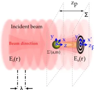
Figure 1: Schematics of DIH principle
For the sake of simplicity, the particle is supposed to be positioned at the centre of the Cartesian coordinate system
Oxyz
, and the sensor (a quadratic imaging surface
, ;
x y zp ) is set to be perpendicular to the z-axis at an axial distance 𝑧 = 𝑧𝑝, as illustrated in Figure 1. In DIH, the
particle hologram is the intensity image of the scattering pattern recorded by the sensor, when it is exposed both to the incident field E ri
(constant) and the field that isscattered E rs
in the forward direction by the particle. Thecorresponding total time-averaged intensity can be expressed as:
LASER-LIGHT AND INTERACTIONS WITH PARTICLES MARCH 5TH-9TH,2018,
COLLEGE STATION,TEXAS
2 i s r E r E r 2 t p p p c I (1)where rp
x, y,zp
is a coordinate vector describing the surface , and
and c are respectively the electrical permittivity and light speed in the medium. By introducing the other intensities, 𝐼𝜒(𝑟𝑝) = 𝜀𝑐 |𝐸𝜒(𝑟𝑝)|2
2
⁄ where , ,
i s t
stand respectively for the incident, scattered and total fields, Eq. (1) can be rewritten as:
2
Ei
Es
t p i p s p p p
I r I r I r e r r (2) The last term in Eq. (2) depicts the interference pattern corresponding to the hologram. Classically, to increase the contrast and eliminate hidden normalization and gain constants, the hologram is conveniently divided by the intensity of the incident field (without particles). Additionally, it is usually assumed that the intensity of the scattered field is negligible compared to the incident field, 𝐼𝑠(𝑟𝑝)/𝐼𝑖(𝑟𝑝) ≪ 1 . Consequently, DIH, which uses the
incident wave as a reference wave, is limited to diluted particle systems. The normalized hologram 𝐼ℎ(𝑟𝑝) can be
simply approximated as follows:
2 Re
i
p s p
t
p -1 h p i p i p E r E r I r I r I r I r (3)To simulate 𝐼𝑡(𝑟𝑝), electromagnetic theories like the
Lorenz-Mie theory (LMT) or the Debye theory can be used. Several authors have demonstrated that this approach is applicable to small particles of micrometer size but becomes quickly prohibitive from a computational point of view for the characterization of large particles with variable composition. For the latter the scalar diffraction theory is preferred especially considering the Fresnel’s paraxial approximation:
2 2
2 2 2 2
k k jk jkz j x y j x y xx yy z z z s p e E r e E r e e dx dy j z (4) where 𝑟′(𝑥′, 𝑦′; 𝑧 = 0) is a coordinate vector describing thesurface Σ′ and Ep
r is characteristic field of the particle to bepropagated to the sensor. The Fresnel approximation is valid only when ka 1and 𝑧 ≫ √𝑘𝑎3 4⁄2
.
In Eq. (4) the field 𝐸𝑝(𝑟′) is the product of the incident field, by
the particle transmission function 𝑇(𝑥′, 𝑦′) = 𝑡(𝑥′, 𝑦′)𝑒𝑗𝜙(𝑥′,𝑦′)
, where 𝑡(𝑥′, 𝑦′) is an amplitude term and 𝜙(𝑥′, 𝑦′) is a pure
phase term. Usually, considering the diffraction of a circular object [11], the term t is modelled by a 2D pupil function. In a similar way, in DIH, a spherical particle with radius ais simply assimilated to a circular hole (or an opaque disk according to Babinet’s principle), with the following transmission function:
2 2 2 , 1, if 0 t x y x y a elsewhere (5) where 𝜙(𝑥′, 𝑦′) = 0.For large particles and far field measurement, the models rely on the several order of magnitude deviation prevailing between the pure diffraction process (partial waves of order
p=-1 [13]) and all other scattering mechanisms: specular
reflection (p=0), single refraction (p=1), etc. [12, 13], allowing to neglect the latters.
Nevertheless, this assumption is not valid in near-field. Indeed, if we consider only the dominant effect after the diffraction process, i.e. single refraction (p=1) for transparent refracting particles (m>1, e.g. droplets or glass beads in water and m<1, e.g. gas bubbles in water) the term 𝑒𝑗𝜙(𝑥′,𝑦′)
accounts for for the angular deviation of the incident rays [14] and cannot be neglected.
In the paraxial approximation, simple ray optics gives for the effective focal length, f, of a spherical object of radius a and relative refractive index m [11]:
2 1
f ma m (6)
with f 0 for refracting particles and f 0 for reflecting ones. This allows to retain the following phase term for a spherical particle [11]:
2 2
, 2 2 k x y ka x y f (7)The combination Eqs. (4) and (7) give for the scattered field:
2 2 2 2 2 2 2 2 2 2 2 2 2
jk z a jkx y z s i jk x y jk jk x y xx yy f z z x y a e E r E e j z e e e dx dy (8)For z=f, the two quadratic phase exponential terms of Eq. (8) cancel each other and 𝐸𝑠 becomes:
2 2 2 2
, ; , jk jk jk z a x y xx yy f f s i e E x y f E e t x y e dx dy j f
(9) Note that in Eq. (9), the integration boundaries have been extended to infinite, and the pupil function reintroduced in order to retrieve a scaled Fourier transform of the particle transmission function. For t1 and a plane wave illumination 𝐸𝑖= 1, 𝐸𝑠 can be written as:
2 2 2
2 1 2 E , ; 2 jk z a jk x y z s p J kar f e x y z f e a j f kar f (10)with for the radial intensity profile:
2 1
2 ; 4 s p J ka f a I z f f ka f (11)LASER-LIGHT AND INTERACTIONS WITH PARTICLES MARCH 5TH-9TH,2018,
COLLEGE STATION,TEXAS
where 𝜌 = √𝑥2+ 𝑦2 and
1
J is the first order spherical Bessel function. The function in Eq. (11) is known as the Airy distribution.
Properties of Airy’s spot produced by a thin lens are widely reported in the literature [15], especially its intensity profile that takes the following form:
2 2 2 2 2 2 2 2 sin 0,0, s km a f a I z f km a f (12)Generally, the transverse and axial characteristic dimensions of the Airy spot are defined by two radii
0.61 /
x
a a f and az2zR respectively, where
2 2
2
4
R
z m a f stands for the Rayleigh distance.
From the foregoing, several conclusions must be highlighted:
The photonic jet predicted by electromagnetic theories [16] and observed experimentally for droplets in liquid-liquid systems [1, 2] can be seen as the Airy’s spot of transparent focusing particle when considering wave optics.
It can be recovered by DIH near-field reconstruction but only roughly evaluated considering geometrical optics approximations as we observe the Point Spread function (PSF) of the lens for zp=f [11].
The particle acts as converging f 0 or diverging 0
f lens depending on the relative refractive index (m 1 or m 1). As the above interpretation is valid for both lenses, the existence of a “virtual” photonic jet (or Airy’s spot) is predictable for the diverging ones.
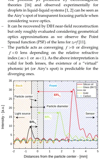
Figure 2: Axial profiles in the near-field, calculated by back-propagating LMT hologram’s simulation, for five particles having the same radius (500µm) and different compositions. DIH parameters: HeNe laser (=0.6328µm), square sensor (with 2000x2000 square pixels of 5.0µm on a side) located at 100mm from the particle center.
3 Numerical and experimental illustrations
The axial profiles, plotted in Figure 2, have been calculated by back-propagating holograms Ih simulated
with LMT. The back-propagation was performed in the Fresnel approximation [1]. Five types of particles dispersed in water are considered in these simulations. They all have the same radius (500µm) but different compositions: two opaque particles (gold and carbon beads) and three transparent particles (air bubbles, silicon oil droplets and glass beads). The first thing to note on this figure is the lack of focalisation peak for the opaque particles (gold and carbon). The second remarkable element is the presence of a maximum of intensity corresponding to the axial profile of the Airy’s spot for the transparent particles. The position of this maximum, compared to the particle’s center, is quite close to the the effective focal length f of the considered lens (respectively -0.7mm, 3.3mm and 2.1mm), confirming that geometrical optics can be used as a first rough but fast approximation. Moreover, when considering particles with a relative refractive index <1, this maximum appears behind the particle. It can be noticed that the axial profiles exhibit an asymmetry not predicted by Eq. (12) probably due to the simplicity of the thin lens model used.
Figure 3: Simultaneous measurement of the relative refractive index and diameter of rising air bubbles (red), rising Isane droplets (blue) and falling glass beads (gray). Black crosses indicate the mean values (diameters and refractive indices), while the dashed lines show the standard deviations at ±1𝜎.
Finally, a classical digital in line holography experimental setup has been used to demonstrate the capability of the method to determine simultaneously the 3D position, velocity, size and composition of flowing particles. The flow-cell consists of a rectangular tank filled with water. Three dispersed phases were considered: free rising droplets of Isane_oil (m=1.0826) and air bubbles (m=0.7505) generated at the bottom of the tank by two drop on demand generators, and a stream of falling glass beads
(m=1.1370). The DIH optical setup was simply composed of
a fiber-injected HeNe laser ( 𝜆 = 632.8𝑛𝑚 , 10mW),
-2 -1 0 1 2 3 4 5 0 5 10 15 20 25 30 35 EFL1 EFL1 EFL1 Particle diameter Front Back Particle center Int en sity - [a. u.]
Distances from the particle center - [mm]
Silicon oil Glass (BK7) Air Gold Carbon Sensor Light source 200 400 600 800 1000 0.7 0.8 0.9 1.0 1.1 1.2 m -m +m -D +D Glass beads Air bubbles Isane oil Rela ti ve re fra ct iv e i nd ex , m [ -] Particle Diameter, D [µm] D
LASER-LIGHT AND INTERACTIONS WITH PARTICLES MARCH 5TH-9TH,2018,
COLLEGE STATION,TEXAS
collimation optics and a S-CMOS camera (2560x2160 square pixels of 6.5µm on a side) placed in Gabor configuration at
zp=100mm. The recorded holograms were back-propagated
using a generalized Fresnel propagator allowing to account for the water-glass-air interfaces as well as astigmatic effects [1,2]. Figure 3 shows some preliminary experimental results; the three populations are clearly recognized.
4 Conclusion and outlooks
In this communication we report that the photonic jet produced by large transparent particles corresponds to the Airy’s spot of a thin lens and can be reconstructed by back-propagation of DIH holograms. This phenomenom is directly linked to refracted rays and cannot be neglected in the near-field. DIH reconstructions display a real image of this spot for refracting particles (m>1), and a virtual image in the case of the reflecting ones (m<1). Furthermore, the spot disappears logically when considering opaque particles. This approach opens up very promising perspectives for multiphase flow extensive characterization, including material recognition.
5 References
[1] Sentis, M.P.L., et al., Digital in-line holography for the characterization of flowing particles in astigmatic optical systems. Optics and Lasers in Engineering, 88:184-196 (2017).
[2] Sentis, M.P.L., F.R.A. Onofri, and F. Lamadie, Photonic jet reconstruction for particle refractive index measurement by digital in-line holography. Optics Express 25(2):867-873 (2017).
[3] Lamadie, F. and L. Bruel, Processing method for near-field in-line holograms (Fresnel number≥ 1). Optics and Lasers in Engineering 57:130-137 (2014).
[4] Kemppinen, O., Y. Heinson, and M. Berg, Quasi-three-dimensional particle imaging with digital holography. Applied Optics 56(13): p. F53-F60 (2017).
[5] Davies, E.J., et al., Evaluating unsupervised methods to size and classify suspended particles using digital in-line holography. Journal of Atmospheric and Oceanic Technology 32(6):1241-1256 (2015). [6] Lee, S.-H., et al., Characterizing and tracking single colloidal particles with video holographic microscopy. Optics Express 15(26):18275-18282 (2007).
[7] Treskatis, S.K., et al., Morphological characterization of filamentous microorganisms in submerged cultures by on‐line digital image analysis and pattern recognition. Biotechnology and bioengineering 53(2):191-201 (1997).
[8] Shpaisman, H., B.J. Krishnatreya, and D.G. Grier, Holographic microrefractometer. Applied Physics Letters 101(9):091102 (2012) [9] Andrews, S., D. Nover, and S.G. Schladow, Using laser diffraction data to obtain accurate particle size distributions: the role of particle composition. Limnology and Oceanography: Methods 8(10): p. 507-526 (2010
[10] Lock, J.A., C.L. Adler, and E.A. Hovenac, Exterior caustics produced in scattering of a diagonally incident plane wave by a circular cylinder: semiclassical scattering theory analysis. JOSA A 17(10):1846-1856 (2000) [11] Goodman, J.W., Introduction to Fourier Optic. (Mac. Graw-Hill, New York, 1960).
[12] Wu, Y., et al., Characterizations of transparent particle holography in near-field using Debye series. Applied Optics 55(3):A60-A70 (2016). [13] Onofri, F., et al., High-resolution laser diffractometry for the on-line sizing of small transparent fibres. Optics Communications 234(1–6):183-191 (2004).
[14] Nye, J.F., Natural Focusing and Fine Structure of Light: Caustics and Wave Dislocations. (London: IOP Publishing Ltd, 1999)
[15] Born M. and Wolf P-E., Principles of Optics (New-York: Cambridge University Press, 1999)
[16] Devilez, A., et al., Spectral analysis of three-dimensional photonic jets. Optics Express 16(18):14200-14212 (2008)