HAL Id: tel-02259929
https://tel.archives-ouvertes.fr/tel-02259929
Submitted on 2 Aug 2019
HAL is a multi-disciplinary open access
archive for the deposit and dissemination of sci-entific research documents, whether they are pub-lished or not. The documents may come from teaching and research institutions in France or abroad, or from public or private research centers.
L’archive ouverte pluridisciplinaire HAL, est destinée au dépôt et à la diffusion de documents scientifiques de niveau recherche, publiés ou non, émanant des établissements d’enseignement et de recherche français ou étrangers, des laboratoires publics ou privés.
Controlling and upscaling laser induced surface
morphology : from tens of microns to tens of nanometres
Fotios Frangelakis
To cite this version:
Fotios Frangelakis. Controlling and upscaling laser induced surface morphology : from tens of microns to tens of nanometres. Micro and nanotechnologies/Microelectronics. Université de Bordeaux, 2019. English. �NNT : 2019BORD0021�. �tel-02259929�
Thèse présentée
Pour obtenir le grade de
Docteur de l’Université de Bordeaux
École doctorale: Sciences Physiques et de l'Ingénieur
Spécialité: Lasers, matières et nanosciences
par Fotios FRANGELAKIS
Controlling and upscaling laser induced surface
morphology: from tens of microns to tens of
nanometres
Sous la direction de : Inka MANEK-HÖNNINGER, Maître de conférences, HDR
Co-encadré par : John LOPEZ, Ingénieur de recherche
Date de soutenance : 14 Février 2019 Membres du jury :
Pr. Antonio ANCONA University of Bari Examinateur
Dr. Jörn BONSE Bundesanstalt f. Materialforschung und -prüfung Berlin Rapporteur
Pr. Evelyne FARGIN Université de Bordeaux Présidente
Dr. Inka MANEK-HÖNNIGER Université de Bordeaux Directrice de thèse
Pr. Gert-Willem RÖMER University of Twente Rapporteur
Dr. John LOPEZ Université de Bordeaux Invité
Acknowledgements
First of all, I would like to warmly thank Inka Manek-Hönninger, John Lopez and Rainer Kling who supervised me throughout this demanding work. I am particularly grateful to my supervisor and friend Girolamo Mincuzzi, who has been constantly present, dedicating time and effort to guide me through the everyday difficulties. In a combined effort, they provided valuable guidance in the most critical points of this thesis.
Second, because this work was a part of the international training network Laser4Fun, I would like to acknowledge all the people that worked to realise and manage the project. They provided a unique research experience. Within the project, I would like to thank particularly the professors Andres Lasagni and Antonio Ancona along with their groups for the warm hospitality during my secondments. I am grateful for all the nice moments we spent together with the Laser4Fun PhD candidates and friends.
Third, apart the participants of the project, I would like to acknowledge George Tsibidis and Evgeny L. Gurevich for the fruitful discussions we had.
Moreover, I owe special thanks to Benoit Appert-Collin director of ALPhANOV and to Eric Mevel head of CELIA for offering me the chance to work in an interesting and diverse environment. To Marie & Sophie, for their aid in dealing with the scary French administrative system. I also thank my colleagues for welcoming me and making a rather pointless effort to teach me French. To Konstantin Mishchik with whom we shared an office for almost three years, having interesting discussions, evenly shared with long quiet hours.
Lastly, I am truly grateful to my companion Mariellen for her support, and to my friend Marko for the good and bad moments we spent together. Without them these three years would not be as nice and successful as they were.
Funding
This work has been founded by the Horizon 2020 Framework Program (H2020) under the Marie Skłodowska-Curie grant agreement (No 675063) and the project Laser4Fun.
2
Summary for the public in English
Current industrial markets demand highly value-added products offering new features at a low-cost. Among the most desired functionalities are, surface colouring and blackenning, anti-icing, anti-biofouling, wear reduction and anti-reflectivity. Functional textures found in nature indicate that those properties can be enable by textures in the micro and nanoscale. Laser surface processing holds a virtually endless potential in mimicking bio inspired textures by modifying surface morphology and chemistry. Several techniques such as polarization control and double-pulse irradiation were investigated in order to achieve controlled laser structuring in the submicron regime. Valuable data were provided both in the surface functionalization, in understanding and controlling of laser induced structuring and in upscaling a lab developed process. The presented results contribute to the exploitation of laser texturing in everyday applications applying up to date laser sources and positioning systems.
Summary for the public in French
L’Industrie actuelle demande des produits à haute valeur ajoutée offrant des nouvelles fonctions à moindre coût telles que la coloration ou le noircissement de surface, la réduction des frottements, la génération de surface antiréflexion, antibactérienne, superhydrophobe ou anti-icing. Les surfaces fonctionnelles présentes dans la nature nous indiquent que ces propriétés uniques ne sont possibles par des texturations de surface à l’échelle micro et nanométrique adéquates. La technologie laser révolutionne le champ des possibles et permet de reproduire ces fonctions inspirées du monde du vivant en modifiant la morphologie et la chimie de surface. Nous avons étudié plusieurs techniques de texturation de surface par laser femtoseconde en jouant sur la polarisation et l’irradiation en double impulsion. Ces travaux de recherche apportent une contribution significative dans la compréhension des mécanismes et dans la capacité à produire de telles texturations sur des grandes surfaces.
3
CONTENTS:
Abstract en français ... 6 Summary ... 8 Synopsis en français ... 10 1. Introduction ... 142. Femtosecond self-organised laser structures ... 20
2.1. Femtosecond interactions with metals: Ultrafast processes ... 21
2.1.1. Electron relaxation ... 21
2.1.2. Thermal effects and resolidification ... 22
2.2. LIPSS formation ... 25
2.2.1. Inhomogeneous energy absorption ... 27
2.2.1.1. Light interference and the efficacy factor ... 28
2.2.1.2. Surface plasmon ... 30
2.2.1.3. Sipe - Drude model ... 31
2.2.1.4. Modelling of light surface coupling ... 34
2.2.1.5. Feedback of the structures & Multi pulse irradiation ... 36
2.2.1.5.1. Collective structure feedback ... 36
2.2.1.5.2. Isolated structure feedback ... 39
2.2.2. Microfluidic motion of the material ... 40
2.3. 2D structure generation & double-pulse irradiation ... 41
2.4. Grooves and spikes formation ... 44
2.4.1. Polarization impact on groove and spike formation ... 44
2.4.2. Fluence impact on groove and spike formation ... 46
2.4.3. Groove and spike formation mechanism ... 46
2.4.3.1. Ablation-based spike formation mechanism ... 46
2.4.3.2. Microfluidic spike formation mechanism ... 48
2.4.3.3. The role of heat accumulation ... 50
2.5. Progress beyond the state of the art ... 51
3. Methods and parameter definition ... 54
3.1. Parameter definition ... 54
3.2. Laser sources, scanning systems and focal lenses ... 55
3.3. SEM characterization ... 55
3.4. AFM characterization ... 56
4
3.6. Materials ... 56
3.7. Double-pulse setup based on delay lines ... 56
3.8. Double-pulse setup based on birefringent crystals ... 58
3.9. Image processing and analysis ... 59
4. Results and discussion ... 60
4.1. Single pulse sequence ... 60
4.1.1. Controlling the morphology at high repetition rates ... 63
4.1.1.1. The role of fluence ... 64
4.1.1.2. The role of overlap ... 65
4.1.1.3. The role of wavelength ... 66
4.1.1.4. The role of repetition rate ... 68
4.1.1.5. Upscaling strategy ... 68
4.1.2. Controlling the laser induced morphology by UV fs laser ... 72
4.2. Double-pulses ... 76
4.2.1. Nanostructures obtained with double pulses ... 77
4.2.1.1. Double-pulses produced by delay line (DL) with Δτ in ps ... 78
4.2.1.2. Double-pulses produced by birefringent crystals (BC) ... 80
4.2.1.3. Double CP pulses produced by BC ... 81
4.2.1.4. Double XP pulses produced by BC ... 82
4.2.1.5. Structure optimization for double-pulses produced by BC ... 83
4.2.1.6. Nanostructures produced with bursts of pulses ... 84
4.2.1.7. Double-pulses in nanosecond regime produced by DL ... 86
4.2.1.8. Surface evolution for increasing dose... 88
4.2.1.9. The plausible role of convection flow ... 89
5. Conclusions ... 92
5.1. Summary of the results ... 92
5.2. Surface functionalities ... 93
5.2.1. Blackening and decorative applications ... 93
5.2.2. Subwavelength grating consisting of ripples ... 94
5.2.3. Superhydrophobic surface enabled by nano roughness ... 95
5.2.4. Holographic colours produced by 2D-LIPSS ... 95
5.3. Conclusion ... 96
6
Abstract en français
L’Industrie actuelle demande des produits à haute valeur ajoutée offrant des nouvelles fonctions à moindre coût. Parmi les fonctions on peut citer la coloration de surface, le noircissement de surface, la réduction des frottements, la génération de surface anti-réflexion, anti-bactérienne, superhydrophobe ou anti-formation de glace. Les surfaces fonctionnelles présentes dans la nature nous indiquent que ces propriétés uniques sont possibles par des texturations de surface à l’échelle micro et nanométrique adéquates. Parallèlement à cela, la technologie laser révolutionne le champ des possibles en termes de texturation de surface et permet de reproduire ces fonctions inspirées du monde du vivant en modifiant la morphologie et la chimie de surface. Néanmoins, le développement et le déploiement de telles techniques de texturation laser au niveau industriel nécessite la levée de trois verrous. Le premier est de connecter les propriétés macroscopiques (couleur, résistance mécanique, stabilité chimique, vieillissement) et la morphologie de surface aux échelles nano et microscopiques. Le second d’acquérir une parfaite maîtrise de la morphologie de surface à ces échelles. Le troisième est la transposition du procédé développé en laboratoire en procédé industriel adapté aux traitements de grandes surfaces avec des temps de cycles les plus courts possibles. Nous avons étudié plusieurs techniques de texturation de surface à l’échelle submicronique par laser femtoseconde. Ainsi des « ripples » de quelques dizaines de nanomètres ont être réalisées par laser UV. L’irradiation avec double impulsion apporte une capacité supplémentaire dans le contrôle de la morphologie de surface finale. Différents types de structures, avec différentes symétries, ont ainsi été produites en jouant sur le délai entre les deux impulsions. Des structures LIPSS homogènes triangulaires ou carrées ont été obtenues pour des délais inférieurs à 5 ps et 500 ps respectivement. Des paramètres opératoires, en particulier la fluence et la polarisation, ont été identifiés comme jouant un rôle majeur dans les caractéristiques de la morphologie de surface finale. Des expériences complémentaires ont montré que des résultats similaires peuvent être obtenus en utilisant des cristaux biréfringents pour générer des délais courts. Nous avons également exploré la possibilité d’utiliser des trains d’impulsions uniques pour produire des texturations de surface de dimensions caractéristiques supérieures allant de quelques microns à plusieurs dizaines de microns en faisant varier de manière systématique la fluence, la dose énergétique et le taux de répétition du laser. La comparaison de résultats expérimentaux avec ceux issus de simulation nous avons mis en évidence le rôle majeur de l’accumulation thermique sur les dimensions caractéristiques des structures générées par laser. Par ailleurs, nous avons démontré la capacité du procédé à produire de texturations sub-longueurs d’onde, homogènes, sur des surfaces supérieures à 1 cm², avec des lasers ayant des taux de répétitions allant jusqu’à 10 MHz et des systèmes de positionnement innovants. Des nano-rugosités de surface ainsi produites affichent des propriétés de super hydrophobicité. A titre d’exemple, nous avons atteint un temps de texturation de l’ordre de 1 min/cm², soit 60 fois inférieurs à ce que nous obtenions en début des travaux. Enfin, nous avons démontré un temps de 9 s/cm² pour le noircissement de surface.
Ces travaux de recherche, mettant à profit des sources laser et des équipements de déflection optique de dernière génération, apportent une contribution significative dans la compréhension des mécanismes d’une part, et dans la capacité à contrôler et à produire de telles texturations sur des grandes surfaces d’autre part. Ils devraient favoriser une dissémination rapide de ces technologies de texturation laser dans l’industrie.
8
Summary
Current industrial markets demand highly value-added products offering new features at a low-cost. Among the most desired functionalities are surface colouring and blackening, anti-icing, anti-biofouling, wear reduction and anti-reflectivity. Laser surface processing holds a virtually endless potential in surface functionalization since it can generate versatile surface properties by modifying surface morphology and chemistry.
Nevertheless, developing functional surfaces for implementation in the industry requires action on three levels. The first is to connect the macro-scale surface properties (colour, mechanical resistance, chemical stability, ageing) and the micro & nano-scale morphology. The second is to increase the level of control over the laser induced morphology in the near micron and submicron scale. The third is to upscale the lab-developed process both in terms of processed area and cycle time.
Functional textures found in nature can be used as a guideline for connecting the surface texture with the surface property. It is well established that different textures can enable different functionalities. Nevertheless, the level of control of the laser induced morphology has to be improved significantly in order to allow one to mimic nature’s examples. Increase of control requires an in-deep understanding of the physical mechanisms that lead to nanostructure formation. To this end, we carry out a comprehensive parametric study of fs processing on stainless steel. The impact of wavelength, spot overlap, fluence, dose, repetition rate, polarization and interpulse delay in the induced morphology was investigated.
We investigate several techniques to achieve controlled laser structuring in the submicron regime. Ripples of a few tens of nanometres were obtained with a UV laser. Double pulses were employed to further control the submicron structures. Structures of different size and symmetry were obtained in different delays underlining the key role of the interpulse delay (Δτ). Homogeneous triangular and square 2D-LIPSS were obtained for Δτ smaller than 5 ps and 500 ps, respectively. Process parameters and particularly fluence and polarization were found to play also a role in the laser induced feature characteristics. In a complementary set of experiments, we show that similar results can be obtained for small delays with a robust setup of birefringent crystals.
In the above micron regime, trains of single pulses were employed for controlling the surface morphology. Fluence, dose and repetition rate, were varied to show a systematic variation of spikes in the range of tens of micrometers. Combining our experimental results with simulation data we underline the key role of heat accumulation on the structures size. Finally, we proposed an upscaling strategy showing the possibility to exploit repetition rates up to 10 MHz for laser texturing.
In the upscaling part, areas much larger than the spot size were textured homogenously using high repetition rate laser and innovative laser positioning systems. Nanometric ripples induced by UV laser act as a subwavelength grating. Laser induced nano roughness exhibits superhydrophobic properties. Uniform distribution of well-defined, sub-wavelength, 2D-LIPSS was successfully generated over ~1 cm2. The final
surface exhibits multiple axis iridescence giving a holographic effect. Employing a 10 MHz fs laser, surface was textured homogeneously with spikes at a rate of ~ 1 min/cm2. Lastly, surface blackening was achieved
at a rate of ~ 9 sec/cm2.
In conclusion, valuable data were provided both in surface functionalization, in understanding and controlling of laser induced structuring and in upscaling a lab developed process. We believe that our results open the way for exploiting fs laser texturing in everyday applications employing up to date laser sources and positioning systems.
10
Synopsis en français
L’Industrie actuelle demande des produits à haute valeur ajoutée offrant des nouvelles fonctions à moindre coût. Des structures à l’échelle micro ou nanométrique ayant des symétrie 2D doivent en principe permettre de conférer des propriétés spécifiques à des surfaces solides. Parmi les fonctions on peut citer la coloration de surface1, le noircissement de surface2, la réduction des frottements, la génération de surface
anti-réflexion3, anti-bactérienne4, superhydrophobe5 ou anti-formation de glace. Les surfaces fonctionnelles
présentes dans la nature nous indiquent que ces propriétés uniques sont possibles par des texturations de surface à l’échelle micro et nanométrique adéquates.
Parallèlement à cela, la technologie laser révolutionne le champ des possibles en termes de texturation de surface et permet de reproduire ces fonctions inspirées du monde du vivant en modifiant la morphologie et la chimie de surface. Néanmoins, le développement et le déploiement de telles techniques de texturation laser au niveau industriel nécessite la levée de trois verrous. Le premier est de connecter les propriétés macroscopiques (couleur, résistance mécanique, stabilité chimique, vieillissement) et la morphologie de surface aux échelles nano et microscopiques. Le second d’acquérir une parfaite maîtrise de la morphologie de surface à ces échelles. Le troisième est la transposition du procédé développé en laboratoire en procédé industriel adapté aux traitements de grandes surfaces avec des temps de cycles les plus courts possibles. Les structurations de surface fonctionnelles présentes dans la nature peuvent servir de guide pour relier la topographie aux propriétés de surface (Figure 1, D, C, E). Ces propriétés dépendent de la topographie et de la physico-chimie de surface.
Cependant, notre capacité à contrôler de telles morphologies de surface induites par irradiation laser doit être améliorée afin d’imiter les exemples présents dans la nature, laquelle nécessite la parfaite compréhension des mécanismes physiques conduisant à de telles structures. Dans cette optique, nous avons
Figure 1 Structures fonctionnalisées; A : pièce de monnaie en argent texturées par laser [1] ; B : ailes d’insecte « Glaswing Butterfly » avec propriétés anti-réflectives [3]; C : bactéries mortes sur aile de cigale [4] ; D : surface de Platine noircie au laser [2] ; E : goutte d’eau sur feuille de Lotus.
11
mené une étude paramétrique sur la structuration de surface induite par laser femtoseconde sur acier inoxydable pour accroître notre capacité à contrôler ces structures aux échelles micro et nanométriques. L’influence de la longueur d’onde6, du recouvrement spatial, de la fluence7, de la dose, du taux de
répétition8, de la polarisation, du délai entre les impulsions a été étudié9–11. Nous avons également mis en
œuvre et étudié plusieurs techniques de telles structures submicrométriques.
Des structures submicroniques, telles des « ripples » par exemple, ont été réalisées et maîtrisées avec succès avec un laser femtoseconde émettant dans l’ultraviolet12. La Figure 2 présente trois structures de surface
obtenues avec un nombre croissant d’impulsion (ppstot). Néanmoins, la variation de paramètres clefs comme
la fluence ou le nombre d’impulsions incidentes ne permet pas de contrôler la symétrie de surface.
L’irradiation avec double impulsion apporte une capacité supplémentaire dans le contrôle de la morphologie de surface finale9–11. La première impulsion induit un état transitoire qui change les propriétés de la matière
vue par la seconde impulsion, lesquelles dépendent directement du délai entre les deux impulsions Δτ. Ce delai est donc le paramètre d’influence principal. Différents types de structures, avec différentes symétries, ont ainsi été produites en jouant sur le délai entre les deux impulsions et le type de polarisation. La Figure 3 présente des nanostructures par irradiation à double impulsions laser sur une surface d’acier inoxydable,
Figure 2 Micrographies MEB de morphologies de surface produites sur acier inoxydables par irradiation avec une longueur d’onde de λ = 257 nm, une fluence de Φ = 0.11 J/cm2 et un nombre variable de nombre total d’impulsios par point ppstot. La flèche en rouge indique l’orientation de la polarisation. Le nombre total d’impulsion est mentionné sur chaque micrographie. Les structures HFSL sont formées pour ppstot = 10, les “ripples” (LFSL) pour ppstot = 50 et les sillons pour ppstot = 100.
Figure 3 Structures produites par irradiation à double impulsion sur acier inoxydable; A : Φ = 0.1 J/cm2, Δτ = 20 ps, H = 1 µm et CP (publié dans 11); B : Φ = 0.1 J/cm2, Δτ = 0.5 ns, pps = 10 and H = 1 m et XP; C: Φ = 0.1 J/cm2, Δτ = -1 ps, pps = 10, H = 1 m and CP D: Φ = 0.15 J/cm2, Δτ = 0.5 ns, pps = 10 and H = 1 m et CP (B,C &D publiés dans 12).
12 tels des plots 2D (Figure 3, A, et Figure 4 C et 4C’), des « ripples » longues et homogènes (Figure 3, B), des structures LIPSS 2D [7], des triangles (Figure 3, C), ou des carrés (Figure 3, D).
Des structures LIPSS homogènes triangulaires ou carrées ont été obtenues pour des délais inférieurs à 5 ps et 500 ps respectivement9. Des paramètres opératoires, en particulier la fluence et la polarisation, ont été
identifiés comme jouant un rôle majeur dans les caractéristiques de la morphologie de surface finale. Le procédé a été optimisé pour produire de telles morphologies sur des surfaces étendues afin de mettre en avant leur aspect visuel macroscopique.
Des expériences complémentaires ont montré que des résultats similaires peuvent être obtenus en utilisant des cristaux biréfringents pour générer des délais courts. Nous ainsi avons démontré que l’irradiation à double impulsions peut être réalisée avec un montage robuste.
Nous avons également exploré la possibilité d’utiliser des trains d’impulsions uniques pour produire des texturations de surface de dimensions caractéristiques supérieures allant de quelques microns à plusieurs dizaines de microns en faisant varier de manière systématique la fluence, la dose énergétique et le taux de répétition du laser8. La comparaison de résultats expérimentaux avec ceux issus de simulation nous avons
mis en évidence le rôle majeur de l’accumulation thermique sur les dimensions caractéristiques des structures générées par laser. Par ailleurs, nous avons démontré la capacité du procédé à produire de texturations sub-longueurs d’onde, homogènes, sur des surfaces supérieures à 1 cm², avec des lasers ayant des taux de répétitions allant jusqu’à 10 MHz et des systèmes de positionnement innovants. Des nano-rugosités de surface ainsi produites affichent des propriétés de super hydrophobicité. A titre d’exemple,
Figure 4 A gauche : micrographies MEB de structures 2D obtenues sur acier inoxydable ; carrés (A et A’), mélange de ripples et plots (C et C’). Clichés correspondant obtenus après Transformée de Fourrier. A droite : photographies de surfaces étendues texturées par laser correspondant aux micrographies MEB indiquées par les flèches rouges et bleues. En haut : motif holographique à deux couleurs obtenue à partir de structurations en carrés ou en triangles comme indiqué. En bas : surface de 8x8 mm texturées avec des « ripples » aléatoires. L’angle indiqué est l’angle azimuthal des platines de rotation.
13
nous avons atteint un temps de texturation de l’ordre de 1 min/cm². Enfin, nous avons démontré un temps de 9 s/cm² pour le noircissement de surface.
Ces travaux de recherche, mettant à profit des sources laser et des équipements de déflection optique de dernière génération, apportent une contribution significative dans la compréhension des mécanismes d’une part, et dans la capacité à contrôler et à produire de telles texturations sur des grandes surfaces d’autre part. Ils devraient favoriser une dissémination rapide de ces technologies de texturation laser dans l’industrie.
Figure 5 Micrographies MEB illustrant la variation progressive du diamètre équivalent δ avec la fluence croissante. Ces micrographies ont été obtenus avec un angle d’observation de 45°. Les valeurs de fluence sont mentionnées sur les clichés.
14
1. Introduction
Current industrial markets demand highly value-added products offering new features at a low-cost. Among the most desired ones are decorative applications, anti-icing surfaces for aeronautic industry, enhanced absorption materials for photovoltaic devices, anti-biofouling components in home appliances and medical applications, wear reduction in automotive industry and anti-reflective properties for photonics applications. Laser surface processing holds a virtually endless potential in surface functionalization since it can generate versatile surface properties by modifying surface morphology and chemistry. Moreover, it is advantageous compared to other techniques used for surface functionalization. For example, creation of composites or applying coatings on a material surface include the use of chemical treatment significantly changing the surface chemistry. Laser processing is more environmentally friendly in this sense, it is long term stable and, in some cases, maintains the surface’s bio compatibility.
Nevertheless, several issues must be tackled prior to laser surface processing implementation in industry. At first, the correlation between the macro-scale properties (colour, mechanical resistance, chemical stability, ageing) and the micro & nano-scale morphology has to be clarified. Secondly, understanding the microstructure formation mechanism will in principle increase the level of control over the laser induced morphology, which we consider limited especially in the submicron regime. The third issue is the limits of the process in terms of surface area process and production cycle time. In parallel to the advances of the laser industry, which can combine high average power laser systems with high speed positioning modules surface processing can deal with large area texturing in the order of 1 s/cm2 13,14. Nevertheless, the study on
controlling laser surface structures is often limited to areas in the order of mm2 and processing rates in
cm2/hour.
In this thesis, both issues will be considered. Industrial high throughput femtosecond (fs) laser sources and innovative laser positioning systems will be employed to demonstrate the feasibility of significantly reducing cycle time while developing novel surface morphologies. Physical phenomena that are subsequent from the increase of average power will be also considered and overcome. Furthermore, considering and implementing innovative spatiotemporal beam shaping and polarization modification can increase control over the structure morphologies from a few tens of microns down to a few tens of nanometres.
The outstanding performance of bio textures on specific functionalities offers valuable information on the characteristics of the optimum nanostructure for inducing specific functionalities. The effort to reproduce bio morphologies using technical means aiming to change surface properties is known as biomimetics. Nature produces a variety of functional surfaces in daily life. Resulting from adaptation to environmental condition biological systems have developed highly efficient functional textures. Specialized macroscopic surface functionalities derive from a particular micro or nanoscale morphology and chemical surface
Figure 6: Functional morphologies and surfaces found in nature reproduced from Fan Xia and Lei Jiang (2008)15. Top: pictures of the living organism. Middle & Bottom: SEM images of the surface textures.
15
composition. Figure 6 illustrates a few examples of microscale functional textures that can be found in nature.
A self-cleaning effect can be found on lotus leaves and duck feathers (Figure 6 , a)15. This self-cleaning
effect is generated on a superhydrophobic surface, when the water droplets exhibit a very high contact angle and small sliding angle, that facilitates the sliding of the droplet washing away any contaminants16. Adhesive
behaviour is observed in gecko feet and octopus tentacles. Special optical properties such as colouring are observed in peacock feathers, butterfly wings and beetle shells. Lastly, anti-reflective behaviour is observed in cicada wings and moth compound eyes15. Anti-friction textures can be found in the katydid leg joints17.
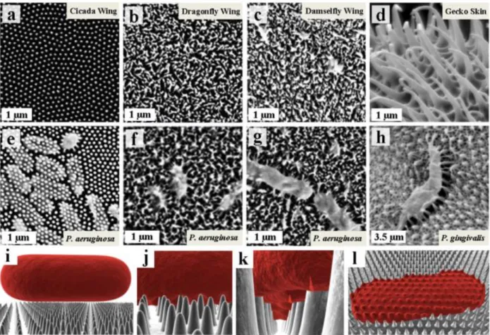
Figure 7 shows SEM surface images of dragonfly and damselfly wings as well as on gecko skin exhibiting anti-bacterial properties16. The surface is shown before (Figure 7, a-d) an after (Figure 7, e-h) inoculation
with bacteria. In all cases the bacteria where killed, whether they can adhere or not on the surface. Elbourne et al.16 coated the cicada wing surface with a 10 nm gold layer to show the effect of the surface morphology
rather than surface chemistry. Interestingly, the gold coated wing maintained the bactericidal behaviour proving that the surface functionality derives from the nano-morphology. In detail, the bacteria’s membrane was distorted and split leading to the death of the cell16. The bactericidal property of the nanostructures is
observed for specific proteinic compositions of the cell membranes and it does not depend on the cells’
Figure 7 Bactericidal surface textures found in bug wings reproduced from A. Elbourne et al. (2017)16. Top: SEM images of (a) Cicada Wings (Psaltoda claripennis), (b) Dragonfly Wings (Diplacodes bipunctata), (c) Damselfly Wings (Calopteryx haemorrhoidalis), and (d) Gecko Skin (Lucasium steindachneri). Middle: SEM images of the wing surfaces when inoculated with (e, f, & g) Pseudomonas aeruginosa ATCC 9027 (P.aeruginosa) and (h) Porphyromonas gingivalis (P. gingivalis). Bottom Row: Schematic representation of bacterial attachment onto the cicada wing nano-pillars showing (i) cellular approach, (j) initial adhesion buckling the cell membrane, (k) the apparent rupture of the cell wall in the region suspended between the nano-pillars, and (l) cell collapse (death) onto the nano-pillars.
16 shape4. Similar findings for the importance of the morphological characteristics of the texture were found
also in the case of transparent surfaces. In that case the structure size, shape and spacing play a key role in the anti-reflective behaviour3.
Developing competence in reproducing the astonishing diversity of bio nanostructures will enable us to induce specialized surface functionalities on a wide variety of materials. Figure 8 (taken from ref. 18)
summarizes the capabilities of different techniques in terms of fabrication speed and feature size. The goal is to achieve control over the feature size in the near micron scale while increasing the processing speed up to m2/min in order to cope with the standards of industrial production. Among other techniques like
lithography, ion beam etching etc, pulsed laser surface processing is a well-established way, utilized to tune the surface of solid materials and its properties. Several approaches of laser processing are commonly employed, namely; direct laser writing (DLW), direct laser interference patterning (DLIP) and surface self-organization.
Direct laser writing (DLW) employs the laser beam to ablate the solid surface and form the structures. The depth of the structures can be defined by the number of laser shots in each point. Short pulse lasers improved the accuracy and reduced the detrimental thermal effect. The main limitation of the technique considering non transparent solid materials is that minimizing the structure size in the submicron scale comes with significant constraints concerning the process throughput19. However, DLW is a very powerful process for
in-volume modifications in transparent materials20.
Direct laser interference patterning (DLIP) is another technique utilized for surface texturing. Structuring with DLIP is based on the generation of an interference pattern of light on the material surface. The inhomogeneous irradiation entails the generation of a temperature gradient followed, depending on the fluence, by surface localized ablation or by microfluidic flow driven from temperature gradients leading to
Figure 8 Summary of the different techniques and the feature size that can be produce. Reproduced from A. Lasagni et al. (2014), ref. 18.
17
structure formation. Similarly, to the DLW process, the depth of the structures depends in principle on the fluence and the number of the incident pulses (Np). Nevertheless, the pulse duration plays a key role and
realization of structures with periods in the order of ΛDLIP < ~10 μm) can form solely with ultrashort
pulses21,22. The main advantage of the technique lies in the fact that the size of the structures can be varied
continuously, and the symmetry can be defined by the number of the interfering beams. Moreover, DLIP can be applied in a variety of solid materials like transparent materials, metals and polymers23 generating
biomimetic surface structures21.
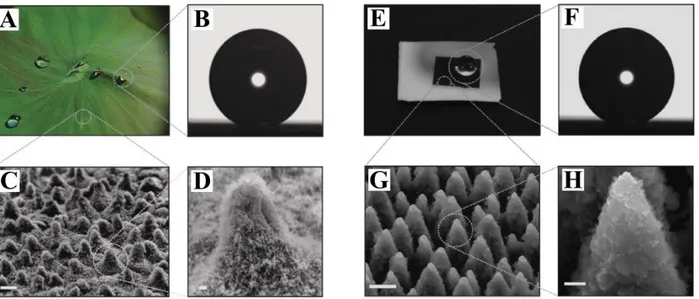
Femtosecond laser surface texturing can be employed to fabricate surface features ranging from a few tens of microns to a few tens of nanometres radically modifying the macroscopic surface properties. The structures appear on the surface after self-organization of the irradiated material, and their formation mechanism is not fully understood up to date. Key process parameters like pulse duration, fluence, number of incident pulses and pulse polarization appear to have huge bearing on the structure morphologies. Laser texturing has been utilized for surface functionalization, and there are several reports of successful fabrication of biomimetic surfaces. Figure 9 illustrates the reproduction of the spiky structures found in lotus leaf (A, C, D), and created by femtosecond laser irradiation on silicon surface (E, G, H). The lotus leaf exhibits superhydrophobic properties due to its hierarchical morphology on micro and nanoscale. The water contact angle on its surface forms a very high contact angle (>150°) as shown in Figure 9, B and a small value of contact angle hysteresis (<5°) is measured. Employing a fs laser source to process silicon surfaces under the presence of a reactive gas5, it is possible to generate hierarchical surface morphologies similar to
the lotus leaf. After surface silanization, the wetting properties are modified radically. The textured surfaces exhibit contact angle values of 154°±1° (Figure 9, F) and hysteresis angles of 5°±2° similar to the lotus leaf5. Hydrophobic metal surfaces can be obtained by inducing similar hierarchical structures. Interestingly,
the wettability of a variety of metallic surfaces has been found to increase progressively after laser irradiation with time due to the uptake of carbon from the atmosphere24. The self-cleaning effect was
demonstrated as well in metallic surfaces processed with fs laser pulses25. Recently, the fabrication of
surfaces with variable wetting properties has been demonstrated highlighting the possibility to achieve unidirectional fluid transport.26
Figure 9 Reproduced from V. Zorba et al. (2008), ref. 5. Lotus leaf (A). Profile of water droplet on lotus leaf (B). SEM images of lotus leaf micro (C) and nano (D) surface texture. Biomimetic, superhydrophobic surface of laser processed silicon (E). Profile of water droplet on laser textured surface. SEM images of laser induced texture on silicon (G & H). Scale bars for C, D, G & H are 10 μm, 1 μm, 5 μm & 1 μm, respectively.
18 Femtosecond lasers can be as well employed for the fabrication of structures in the submicron regime. As discussed above (§1), submicron structures are ideal for enabling unique surface properties such as bactericidal and antireflective. So called laser induced periodic surface structures (LIPSS) have been fabricated in a variety of materials such as semiconductors27,28, metals29,30 and transparent materials31,32.
LIPSS are found to be quite effective on enabling antibacterial and anti-friction properties33. Femtosecond
irradiation has been employed to mimic bio-, micro- and nano-texturing in order to reproduce nature functionalities on solid surfaces 5,26. Several previous works refer to modifications of optical properties like
surface blackening34, tribological performances35, surface wettability5 and bacterial adhesion selectivity.33,36
Comparative studies between different nanostructures fabricated on stainless steel surface, showed that hydrophobic spikes are not bactericidal37 providing further support to the hypothesis that specific surface
functionalities derive from specific surface morphologies. Therefore, controlling the surface morphology and especially in the submicron regime is essential for developing functional surfaces.
In this thesis, §2 will be dedicated to the fundamental aspects of laser mater interaction and the proposed mechanisms that lead to laser induced structure formation. In §3 the experimental methods will be discussed. In §4 the results on controlling and upscaling laser induced morphology are presented. Finally, conclusions will be summarized in §5 and an outlook on potential nanostructure applications will be presented.
20
2. Femtosecond self-organised laser structures
Controlling laser induced self-organized morphologies requires an in-depth understanding of the fundamental processes that lead to their generation. It is reported that multi-pulse, or under specific conditions single pulse38 irradiation of solid surfaces leads to formation of laser induced periodic surface
structures the so called LIPSS39. Femtosecond lasers facilitate the generation of LIPSS in a variety of
materials ranging from semiconductors27,28 to metals29,30 and transparent materials31,32. LIPSS morphological
characteristics such as period, depth and structure homogeneity40 are predominantly determined by the laser
wavelength, polarization41–44, fluence34, the number of incident pulses34,45–47 and the temporal intensity
profile of the irradiation48,49. Moreover, it is reported that structure formation can be also influenced by the
spot size40, the ambient gas presence and pressure45.
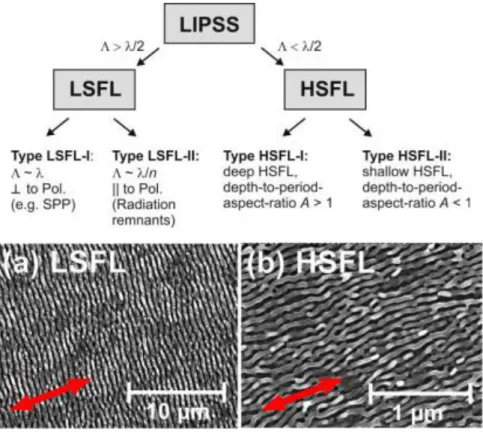
A classification of the laser induced periodic structures is presented in Figure 10, top. High spatial frequency LIPSS (HSFL) appear for low fluence value (Φ = 0.08 J/cm2)i on the surface42,50–53 perpendicular to the
lasers polarization in highly absorptive materials42 (Figure 10 bottom, b). Low spatial frequency LIPSS
(LSFL) are formed when a dose threshold (either in terms of fluence or number of pulses) is exceeded51. In
Figure 10 bottom A, LSFL are shown obtained with Φ = 0.11 J/cm2. Afterwards and above a specific fluence
threshold53,54, for large number of pulses (N
p > ~10) grooves and then spikes are formed on the surface of
semiconductors46,54–56 and metals.
In the case of femtosecond irradiation of solid surfaces, the structure formation mechanisms remain quite unclear and several theories attempt to interpret LIPSS formation. We mention for instance: surface plasmon polariton excitation39, surface self-organization 57 , or the interaction between surface roughness
and the incident electromagnetic field58. Generally, the structures result from inhomogeneous energy
i A specific threshold is observed depending on the material for the LSFL formation. Below that point and above the
melting threshold of the material, HSFL are formed in semiconductors55 and metals.
Figure 10 (Reproduced from ref. 42) Top: classification of LIPSS types. Bottom: SEM images of Titanium alloy textured with a: LSFL, b: HSFL
21
absorption during the irradiation39 that leads to a periodic temperature profile on the material surface
followed by microfluidic movement of the molten material27,46,48. An insight on the surface evolution during
the ripple formation has been acquired by pump-probe experiments in silicon59–61 and in metals62. The
complex dynamical processes of interaction will be discussed in §2.1 and the proposed mechanisms of structure formation in §2.2 - 2.4.
2.1.
Femtosecond interactions with metals: Ultrafast processes
In the case of femtosecond laser irradiation of semiconductors63 and metals, the electrons absorb a part of
the incident laser pulse energy in the order of 30% - 40%50,64 with the rest being reflected or scattered by
the surface. The absorbed energy initiates several interdependent relaxation mechanisms that determine the overall process, each one with a characteristic time scale:
2.1.1.
Electron relaxation
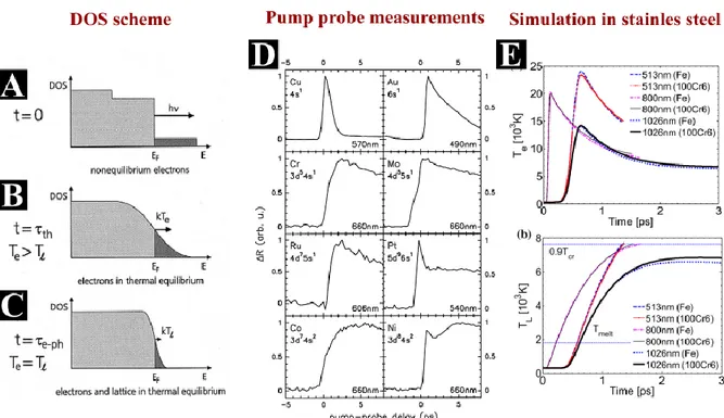
When the electron-phonon coupling time is longer than the pulse length, as for sub-picosecond pulses, the electrons and the lattice have different temperatures immediately after the laser irradiation65. Excited
electrons relax, transferring the energy to the lattice thanks to electron-phonon coupling within a few picoseconds27,64,66–68. As shown schematically in Figure 11 A, a group of electrons that absorbed the pulse
energy are excited above the Fermi level. Afterwards the electrons reach thermal equilibrium (Figure 11 B). Electron excitation modifies the optical properties of the surface of the material within the first picoseconds after irradiation50,69. Changes in the surface reflectivity R can be visualized and measured via pump-probe
experiments. In detail, the relation between the relative change of reflectivity ΔR/Rii and the electron
ii𝛥𝑅 𝑅 = 𝑅(𝑇𝑒)− 𝑅(293𝐾) 𝑅(293𝐾) as described in ref. 65
Figure 11 Electron phonon interactions, theory measurement and simulations A, B, C Density of state (DOS) scheme. Reproduced from ref 65. D pump-probe measurements of the reflectivity changes after irradiation with fs pulses reproduced from65. E: Simulations of electron relaxation and lattice thermalization in 100cs steel for different wavelengths and pulse durations reproduced from 64.
22 temperature Te, which depends on the electronic band structure and the probe wavelength, permits the direct measurement of the electron lattice equilibration process65. Two mechanisms are responsible for electron
relaxation, hot electron diffusion and electron phonon interactions65. The electron diffusivity and thermal
conductivity vary with the electron temperature70. Lastly, the strength of the electron phonon coupling
determines the time that the electrons need to equilibrate with the lattice (Figure 11 B)65. Pump-probe
measurements of the electron relaxation behaviour show a varying characteristic time behaviour for different metals (Figure 11 D)65.
Our study will be focused on nanostructuring of stainless steel, and therefore defining the time of electron relaxation is essential for the data interpretation. Recent simulation studies on LIPSS formation on 100CR steel gives the characteristic timescales for this material64. Figure 11 E, shows the electron (top) and the
lattice (bottom) temperature on 100CR steel surface after excitation of femtosecond pulses with different pulse durations and wavelengths. A characteristic time in the order of 1-2 ps is necessary for the lattice thermalization64.
2.1.2.
Thermal effects and resolidification
After the lattice thermalization, if a specific energy threshold is exceeded, the material surface undergoes a phase transformation. Depending on the fluence of the laser pulse the material surface can undergo melting, photomechanical spallation driven by a laser induced shockwave or an explosive disintegration of an overheated surface layer71 with a remaining molten layer. For ultrashort pulse (USP) irradiation, the heating
of the material is realized in timescales that do not permit the smooth transition between the phases of the material. If the deposited energy is sufficient for the material to exceed the boiling point, the material will be in an unstable phase. That will prevent the boiling of the material (heterogeneous nucleation) and the sudden increase of surface temperature will lead to homogeneous nucleation and ablation72. The
resolidification time is estimated to be in the nanosecond regime63,71. Furthermore, it is shown that the
Figure 12 (reproduced from ref 75) Ellipsometric pump-probe measurements. A: microscope images of Mo sample after irradiation with Φ = 0.8 J/cm2. The probe time delay is indicated. B: Evolution of n and k after irradiation with different wavelengths as indicated. Left: Φ = 0.3 J/cm2 (below ablation threshold), right Φ = 0.8 J/cm2 (above ablation threshold).
23
portion of material in the molten phase depends on the laser wavelength64 and the fluence73 as well as on
the occurrence of ablation71.
Pump-probe measurements during the transient surface state provide detailed information on the characteristic timescales of the processes. Pump-probe ellipsometry measurements can be utilized for deriving the values of the real part (n) and the imaginary part (k) of the material’s refractive index 74,75.
Ellipsometry measurements require a non-zero incident angle and a known polarization state for the probing beam76. After the reflection of the pulse, its polarization state is changed, and the analysis of the polarization
components provide information about the properties of the material75. Figure 12 illustrates results obtained
with a pump-probe ellipsometric measurement after irradiation of a molybdenum surface. A series of images of molybdenum surfaces is shown (Figure 12 A) after irradiation by a F0 = 0.8 J/cm2, τ = 680 fs, λIR = 1056
nm (pump pulse) and probed by a τ = 540 fs, λ= 528 nm pulse. The delay of the probe pulse is indicated. The values of k and n shown in Figure 12 B are derived from the acquisition data for two different fluence values Φiii; below the ablation threshold when Φ = 0.3 J/cm2 (Figure 12 B left) and above the ablation
threshold when Φ = 0.8 J/cm2 (Figure 12 B right)75. The solid and opaque lines represent excitation by IR
and green pump pulses, respectively75. Transitions are observed at zero when the irradiation of the pump
pulse occurs. Below the ablation threshold (Figure 12 B left), the n value decreases within the first 5 ps and remains stable until 40 ps. This transition is correlated to the heating and phase changes expected to occur in that timescale. Later, n increases again until stabilizing between 100 ps and 300 ps while almost reaching the initial value75. The stabilization of n is linked to the solidification process expected at that regime77. Yet
the final value of k is slightly lower than the initial indicating the permanent change in the optical properties of the material. Similar behaviour is observed for both wavelengths75. By increasing the fluence above the
threshold the overall behaviour changes: The first transition occurring below 5 ps is steeper and is followed by a continuous decline75. These transitions can be identified with the surface heating and ablation onset
expecting to occur between 10 ps and 50 ps75.
Similar times for the initiation of the thermal effects were obtained for metals and semiconductors. For example, in Cr irradiated with 200 fs and with an absorbed fluence of Φ= 0.2 J/cm2 - 0.3 J/cm2 material
expansion starts at 5 ps78 and the ablation depth is estimated to be in the order 40 nm78. In thin film Ag
irradiated with Φ = 0.46 J/cm2 a signal decrease in the first 30-50 ps indicates the melting of the surface.
The resolidification starts for t > 50 ps and is completed within 200 ps – 300 ps79. Pump-probe measurements
in silicon59 show the sequence of surface states for single pulse irradiation and fluence Φ = 0.14 J/cm2. The
first effects are observed at Δτprobe = 150 fs when a slight increase of the reflectivity is observed. The change
is intensified within a few hundreds of fs and is stabilized after a couple of ps, when thermal melting of the material is expected59. In germanium irradiated by fs pulses and Φ = 1.32 J/cm2 (above ablation threshold),
the irradiation induces an increase of the surface reflectivity directly after the pump pulse due to electron excitation which can destabilize the lattice structure59,80. The onset of ablation is expected approximately
100 ps after the irradiation80.
Simulations of the post irradiation behaviour of the excited surface affirm the timescales derived from pump-probe experiments. Characteristically, a comparative study including simulation and experiments in copper indicates that electron-phonon relaxation is completed within ~3 ps, the maximum ion temperature is reached after 10 ps (1.9 J/cm2 τ = 680 fs and λ = 1056 nm), and the ablation process with mechanical motion
starts after ~20 ps81. In Figure 13 A the evolution of the molten surface layer and the temperature are
shown73. Simulations in Ni,71 showed that irradiation with 1 ps laser pulses for fluences within the range of
Φeff = 0.03 J/cm2 to Φeff = 0.17 J/cm2 entails fast and slow melting of the surface71. The two melting speeds
24 derived from the graphs; as shown in Figure 13 C show that fast melting results in liquification of 50 nm within 30 ps and an increase of the melted layer of additional 15 nm due to slow melting within 500 ps71.
The heating and the hydrodynamic motion of the material that leads to surface expansion could last several tens71 or in some cases hundreds62 of ps. The surface deformation is related to the physical mechanism of
pressure relaxation governing a highly pressurized melted surface layer62. A characteristic timescale in the
case of ablation related to the speed of sound ts ≈ 90 ps was derived for Zn62.
As intuitively expected, in sub-ablation conditions the depth of molten layer as well as the resolidification time depend on the amount of effective energy delivered on the surface73. Simulations on Ni unveil the role
of fluence in determining the depth of molten layer and the resolidification time 71,73. The dependence of the
molten layer depth on the fluence is explicitly illustrated in Figure 13 B, where simulation results are depicted from irradiation of Ni targets by a 50 fs laser pulse at different values of absorbed laser fluence (marked in the plot in units of J/cm2)73. Simulations of fs-induced melting of bulk Ag are in line with this
approach describing surface expansion and homogeneous void generation 25 to 55 ps after irradiation82.
Interestingly, as the fluence increases and the ablation threshold is surpassed (Φeff > 0.17 J/cm2), the
resolidification time becomes smaller due to the reduction of the molten layer thickness71. The time for
Figure 13 A: Simulation of the evolution of the depth of molten part in the surface of Ni and the surface temperature (reproduced from ref71). B: Melting depth and resolidification times in subablation conditions after irradiation of Ni surface with a 50 fs laser pulse at different values of absorbed laser fluence (marked in the plot in units of J/cm2), reproduced from ref 73. C: Melting depth and resolidification times after irradiation of Ni surface with different fluence values around the ablation threshold (reproduced from ref 71). D: Time of maximum melting of Ni surface after irradaition with different fluence values (reproduced from 71).
25
reaching the maximum depth of molten layer (Figure 13 D) follows the same trend71. In sub ablation
conditions a maximum is observed around 500 ps71. The maximum depth of the melted layer is as well
fluence dependent and decreases when the ablation regime is entered as shown in Figure 13 C.
At longer times the cooling of the material due to heat dissipation from the surface to the bulk leads to resolidification of the surface molten layer. The fluence has a big impact in determining the resolidification time (τsolid). In Figure 13 B a proportional relation of absorbed fluence value (marked in the plot in units of
J/cm2) to the resolidification time can be observed73. In this case it varies from τ
solid ≈ 600 ps for Φeff = 0.03
J/cm2 to τ
solid ≈ 3 ns for Φeff = 0.17 J/cm2. In another work, irradiation with Φeff = 0.17 J/cm2 which is defined
as the ablation threshold on Ni surface, a resolidification time of 2.4 ns was derived71. Simulations in Cr of
irradiation with Φ= 0.2 J/cm2 - 0.3 J/cm2 show that the surface remains liquid for at least 2 ns78. An estimated
time for the resolidification of τsolid ≈ 2.5 ns was derived for Al83.
Depending on the material, pump-probe measurements give slightly longer times for resolidification. For pump-probe in silicon, the melted phase of the material is reported to end in between 3 ns and 4 ns59.
Pump-probe measurements in germanium report that depending on the fluence, the material solidifies after a few to a few tens of ns80. Similar observations carried out with pump-probe techniques, elaborating on the
fluence impact on the resolidification time of Zn give τsolid in the order of tens of ns62.
After resolidification the surface of the material maintains several hundreds of degrees and the time of cooling of the material to room temperature is estimated to about 10 μs77. During high repetition rate surface
processing, when the repetition rate of the laser is set above a few hundreds of kHz, the time interval between the pulses is not sufficiently large for the heat to be dissipated84.
2.2.
LIPSS formation
In this paragraph, LIPSS formation is discussed. At first, an introductive part will be dedicated to the observation of LIPSS formation via pump-probe experiments. That way the characteristic timescales of the process will be mentioned. Afterwards, a detailed discussion of the proposed physical mechanisms that lead to LIPSS formation will be presented.
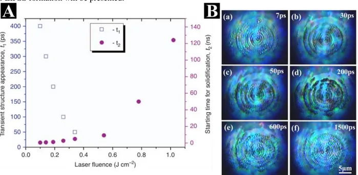
Figure 14 Characteristic times for structure appearance (t1) and starting time for resolidification (t2) of Zn after irradiation with different fluence values as indicated. Reproduced from62. B: Optical micrographs showing ripples emerge on silicon surface after irradiation with the third femtosecond pulse (N=3). The images indicate the probe pulse delay. Reproduced from ref 60.
26 At suitable conditions, usually close to the ablation threshold, ultrashort pulse laser irradiation of solids entails the formation of structures on the surface. The surface morphology changes during the transient surface state, and when it is solidified the novel features are permanently integrated on the material surface. Their formation mechanism will be discussed in this chapter.
As extensively discussed in § 2.1, the laser induced morphological changes on the surface starts in the time regime of tens to hundreds of picoseconds60 and the surface resolidifies in the nanosecond
timescale59,62,71,73,85. LIPSS appearance occurs in the time in between the two processes. The graph in Figure
14 A, gives a general overview of the structural appearance time with respect to the irradiated fluence of the incident pulse in the case of Zn irradiated with a 65 fs-pulse at a wavelength of λ = 800 nm. Comparing the images of the transient surface state and the images of the surface at a final state, significant statements can be made for the structure formation timescales62. For example, in the case of Φ = 0.1 J/cm2 the surface
structures begin to appear at a time delay (Δτprobe) of 400 ps, the observed structures are considered transient
since they are not alike to the final morphology62. Similarities between the morphology observed at Δτ probe
= 527 ps and the final structures indicate the starting of the resolidification62. Around 90% of the structures
are frozen at Δτprobe = 50 ns62. In the regime of 0.1 J/cm2 - 0.14 J/cm2 the onset of a transient structure
Figure 15 (reproduced from ref59) A: reflectivity measurements of silicon surface at different probe pulse delays B: Single shot reflectivity measurements on silicon surface indicating the timescales of ultrafast processes. C: Relative change in the reflectivity
27
formation occurs between Δτprobe = 400 ps and Δτprobe = 300 ps, respectively, due to the time delay necessary
between the melting process and the hydrodynamic motion of the material62.
Pump-probe visualization of the ripple formation process was also carried out in silicon60. In Figure 14 B
the evolution of a silicon surface after irradiation with a 120-fs laser pulse with λ = 800 nm is shown for different probe delays (Δτprobe). The temporal resolution of the experiments was 1 ps. The fluence was Φ =
0.61 J/cm2 and the probe images were obtained after the third pump pulse incident on the same spot (N =
3)60. The morphology does not change before Δτ
probe = 7 ps60. Between Δτprobe = 7 ps and Δτprobe = 200 ps
the destroyed regions become darker, due to absorption of the incident pulse by charged particles and silicon atoms ejected from the surface60. This observation is in agreement with the expected time of ablation as
discussed in §2.1.2. The rudiment of ripples is found at Δτprobe = 50 ps and their formation lasts until Δτprobe
= 600 ps whilst after Δτprobe = 1500 ps the surface morphology does not change60. Similar results were
obtained for a pump-probe experiment that is capable to visualize simultaneously the response for different pulse numbers on the silicon surface59. Thanks to the ultrafast moving spot microscopy, visualization of
ripples irradiated with a different number of pulses was possible59. In Figure 15 B the temporal evolution of
the reflectivity of silicon surface is presented after irradiation for a single laser shot having Φ = 0.17 J/cm2.
The differences in the reflectivity are linked to different stages of the surface transient state; electron population temperature and band structure as well as lattice temperature and surface’s phase. The peak of reflectivity is observed for Δτprobe = 7 ps and points towards thermal melting related to electron lattice
equilibration59. A detailed view in time and in number of incident pulses is presented inFigure 15 A. Figure
15 C shows the evolution of the reflectivity over time for different numbers of pulses demonstrating the change of the optical properties of the material change upon an increasing number of pulses and nanostructure generation59. The resolidification process starts around Δτ
probe = 1 ns and lasts 1.3 to 1.5 ns.
Finally, the material surface resolidifies before Δτprobe = 4 ns59.
Even though the visualization of LIPSS formation is accomplished and ripple appearance was found to coincide with the ablation process60,62 and the surface’s melted phase59,60,62 their formation mechanism is
highly debated and still remains unclear. The main debating point is whether the ripple formation results from the way the laser pulse is absorbed or from the way the surface relaxes after excitation42. The first
approach attributes the ripple periodicity to the excitation of a surface plasmon wave39,69 while the second
in the self-organization of the surface57. The proposed mechanisms of ripple formation will be discussed in
the following chapters.
2.2.1.
Inhomogeneous energy absorption
It is generally proposed that during surface irradiation, periodic fluence allocation on the materials’ surface occurs during irradiation driving LIPSS formation. Strong experimental indications point out in this direction50,59,86. A systematic study of the cavitation formation on Ni surface provide proof for the
inhomogeneous absorption of the laser light during the irradiation50. At first by observing a cross section of
Ni surface before ripple formation, it is demonstrated that the cavitation formation is fluence dependent (Figure 16)50. In the areas that are in the outer rim of the crater (distance from the center > 5μm), which
have received smaller fluence during irradiation due to the pulse’s gaussian profile, cavities are formed just below the surface (Figure 16, B, top)50. As the radial distance decreases below 3 μm, the cavities disappear
and surface nanostructures with periods smaller than 200 nm are formed (Figure 16, B, bottom). After increasing the number of pulses, a structured area including HSFL and LSFL is produced (Figure 16, C). As shown in Figure 16, below the surface of the crest areas, nanovoids are formed and frozen indicating low absorption intensity while the absence of voids in the valleys point out high intensity. Therefore, a
28 periodic alteration of cavities and crests results from the periodic intensity distribution during the irradiation indicating constructive and destructive interference of the incident electromagnetic wave50.
Similar findings were acquired in the sub-ablation regime where an amorphous grating mark was formed on a GeTe surface after irradiation with fs laser pulses86. The origin of the periodic crystal and amorphous
pattern is attributed to the interference of the incident pulse with a surface electromagnetic wave or Rayleigh scattering86. The understanding of the laser-surface coupling was enriched during the past decades. An
overview of the works that founded this understanding will be presentenced here.
2.2.1.1. Light interference and the efficacy factor
The mechanism that is ultimately leading to periodic absorption of laser light and the ripple formation has been investigated under different perspectives. Emmony et al.87 proposed that the origin of ripple formation
was the interference of the incident electromagnetic wave with a secondary wave produced by light scattered from a surface feature and he introduced Equation 1 for the ripple period87.
Equation 1: relation between the ripple spacing (d), the incident angle (θ) and the irradiation wavelength (λ).
𝑑 = 𝜆/(1 ± 𝑠𝑖𝑛𝜃)
Figure 16 (reproduced from ref. 50) SEM and cross sections of Ni surface after irradiation with fs pulses. A: Φ = 0.38 J cm−2, Ν = 2. Β: Cross section of areas corresponding to different radial distances from the center as indicated.
29
Z. Guosheng, et al. proposed a model according to which an interference of the incident beam with an optical wave travelling along the surface was responsible for the ripple formation88. The model was based on the
observation that the laser period varies with respect to the incident angle89. In his model the surface
roughness consists of random surface features88. These features can be viewed as a superposition of many
different surface gratings with different spatial periods each one diffracting the incident light into a number of diffracting orders88. The diffracted light will interfere with the primary incident wave to produce an
intensity pattern88. The components with periods given by Equation 1 will diffract light along the surface of
the material.
Sipe et al.39 further developed this model, describing
analytically the mechanism behind inhomogeneous energy absorption by the surface. A thin rough layer (d<<λ) shown schematically in Figure 17, scatters the incident electric field, generating a component which interferes with the refracted beam and leads to inhomogeneous absorption just below the rough surface (selvedge)39. The absorption of the incoming
laser energy depends on the cross product of the absorption efficacy factor (η) and the roughness amplitude (b), η×b. The so called “efficacy factor”, η, is a function describing the efficacy that a surface roughness leads to inhomogeneous absorption. In this concept, surface roughness can be analysed by a superposition of gratings with different spatial frequencies. b is a measure of amplitude of surface roughness at k, which is the incident wavevector parallel to the surface of magnitude |𝑘| = (2𝜋 𝜆) 𝑠𝑖𝑛𝜃⁄ 𝑖𝑛𝑐39. The efficacy factor η exhibits sharp peaks at frequencies close to the incident wavevector
which can be correlated to the ripple period39,69. After ripple formation, b exhibits also sharp peaks which
coincide with the peaks of η, entailing the significant increase of the efficiency of inhomogeneous absorption69 and described as feedback of the structures90.
A flat surface is progressively roughened by the incident pulses. During the first shots the surface is progressively roughened randomly50,90. The coupling of the electromagnetic radiation with the surface is
determined by the pre-existing surface morphology50 as well as by other factors like polarization and fluence
that affect the optical properties of the material50. The roughness which is laser induced enables the
scattering of the following incident laser pulses entailing the ripple formation90. The relation of the ripple
orientation with respect to the laser polarization can be attributed to the interference between the scattered surface wave and the incident light that defines the axis of the periodic modulation of the absorbed light intensity90.
The efficacy factor model was employed in a comparative study between simulation results and experimental data of irradiation of indium phosphide with fs pulses. A theoretical prediction of the ripple period was in good agreement with the experimental data90. The experimental part includes the irradiation
of indium phosphide with λ = 800 nm, τp=130 fs and Φ = 0.58 J/cm2. On the surface, after irradiation with
the first laser shot a crater is formed. For Niv ≥ 2 ripples appear on the surface. The 2D-FT maps of the
scanning force microscopy (SFM) images of the surface are shown in Figure 18 for different numbers of pulses (a: Np = 1, b: Np = 2, c: Np = 3, and d: Np = 4). After the second laser shot periodical features on the
surface, with a period close to the laser wavelength are observed (Figure 18, b). Upon increasing the number of pulses, the amplitude of the 2D-FT diagram corresponding to the period of the ripples is becoming clearer (Figure 18 c & d). The extracted period value is Λ ~ ± 750 nm and very close to the irradiation wavelength
iv N
p is the number of incident pulses. See §3.1 for details. Figure 17 (Reproduced from ref. 39) The geometry
![Figure 1 Structures fonctionnalisées; A : pièce de monnaie en argent texturées par laser [1] ; B : ailes d’insecte « Glaswing Butterfly » avec propriétés anti-réflectives [3]; C : bactéries mortes sur aile de cigale [4] ; D : surface de P](https://thumb-eu.123doks.com/thumbv2/123doknet/12860671.368524/16.918.112.813.289.705/structures-fonctionnalisées-texturées-glaswing-butterfly-propriétés-réflectives-bactéries.webp)