HAL Id: hal-01476875
https://hal.archives-ouvertes.fr/hal-01476875
Submitted on 3 Mar 2017
HAL is a multi-disciplinary open access
archive for the deposit and dissemination of
sci-entific research documents, whether they are
pub-lished or not. The documents may come from
teaching and research institutions in France or
abroad, or from public or private research centers.
L’archive ouverte pluridisciplinaire HAL, est
destinée au dépôt et à la diffusion de documents
scientifiques de niveau recherche, publiés ou non,
émanant des établissements d’enseignement et de
recherche français ou étrangers, des laboratoires
publics ou privés.
FREQUENCY CONTROL FOR EFFICIENT AND
CONVENIENT DIODE LASER LINE NARROWING
Michel Lintz, Jean-Pierre Coulon, Duy-Ha Phung, Benoit Faure, Thomas
Lévèque
To cite this version:
Michel Lintz, Jean-Pierre Coulon, Duy-Ha Phung, Benoit Faure, Thomas Lévèque. DUAL,
FEED-FORWARD + FEED-BACK LASER FREQUENCY CONTROL FOR EFFICIENT AND
CONVE-NIENT DIODE LASER LINE NARROWING. International Conference on Space Optics (ICSO 2016),
Centre National d’Etudes Spatiales, & European Space Agency, Oct 2016, Biarritz, France.
�hal-01476875�
DUAL, FEED-FORWARD + FEED-BACK LASER FREQUENCY CONTROL FOR
EFFICIENT AND CONVENIENT DIODE LASER LINE NARROWING
Michel LINTZ (*)1, Duy Ha PHUNG (
◊)1*. Jean-Pierre COULON1, Benoit FAURE2, Thomas LEVEQUE2
1Université Côte d'Azur, CNRS, Observatoire de la Côte d'azur, Laboratoire ARTEMIS, Boulevard de l'observatoire, Nice, France.
2CNES, 18 rue Edouard Belin, Toulouse, France.
INTRODUCTION
Distributed feedback (DFB) diode lasers are convenient, small footprint and robust single mode laser sources. Control of the diode forward current allows for the control the frequency of the emitted laser beam. Locking the laser frequency to some optical frequency discriminator, such as an optical interferometer or an atomic or molecular line, can easily be achieved. Such a lock, with a moderate (< kHz) bandwidth can prevent long term drifts of the laser optical frequency. On the other hand, reaching high lock bandwidth (> MHz) can lead to laser line narrowing. DFB lasers have an emission linewidth in the MHz to several MHz range, which may be too large for some applications, such as cold atom physics, optical clocks, laser ranging, lidar or gas sensing...
We have tried to achieve a high bandwidth in the lock of a DFB diode laser with a feedback loop using both the laser diode forward current and an optoelectronic external modulator. A lock bandwidth in the MHz range has been obtained, and the optical spectrum shows narrowing. But a significant fraction (15-20%) of the optical power remains broadband. By contrast, much more efficient and convenient operation has been found when the external electro-optical modulator is not in a feed-back loop but in a feed-forward configuration. The optical spectrum shows a half width at half maximum of 3 to 4 kHz, with about 1% of residual broadband optical power. The system allows implementation at any wavelength, if the frequency discriminator is obtained from a Michelson interferometer with gold-coated mirrors.
I. PRINCIPLES
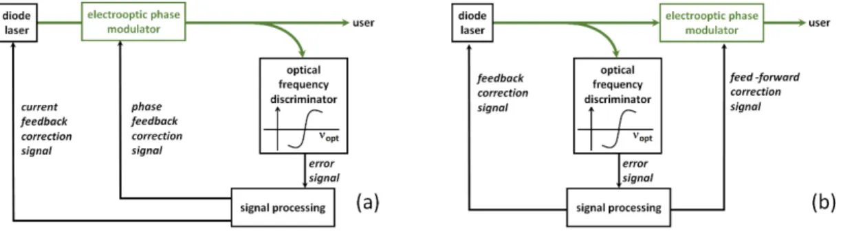
To reach high bandwidth in the control of the emission spectrum of a diode laser, it is natural to combine an electrooptic, external phase modulator and the control of the laser diode direct forward current. The latter allows convenient control of the optical frequency of the laser. The gain at DC is in the GHz/mA range at DC. This value drop with modulation frequency (as expected for a thermally-induced index change) until the MHz range where the index change associated with the carrier distribution starts to dominate: this gives rise to a complex transition behavior that complicates lock loops with MHz bandwidth. The addition of an electrooptic modulator provides control of the optical phase with a flat gain well above 100 MHz, but combining the two actuators can be achieved in a (double) feedback loop, or a feed-back + feed-forward configuration, as illustrated in Fig.1 (a) and (b), respectively.
Fig. 1. Basic scheme for (a) double feed-back loop and (b) "dual", feed-back + feed-forward configuration with
an external electrooptic phase modulator. Green line: optical fibre.
In a naive approach, both configurations provide reduction of the error measured in the optical frequency discriminator, but the feed-back loop implements
0
1
→
+
G
FBerror
frequency
optical
(1) whereG
FB, the feedback loop gain, has to be as large as possible, over a bandwidth as large as possible, yet meeting the stability conditions. On the other hand, the feed-forward configuration implements0
)
1
(
)
(
optical
frequency
error
×
−
G
FF→
. (2)If a large reduction of the frequency error is to be achieved, the gain
G
FF of the feed forward actuator has to be very close to one, over a large bandwidth: by contrast with the feedback loop configuration, stability is irrelevant, but gain flatness and accuracy can be demanding.Although feed-forward control has not been frequently used, it has been studied and implemented in [1] in the framework of the locking of a DFB diode laser to a frequency comb. However the setup used an acousto-optic frequency shifter (AOFS) as feed-forward optical frequency actuator, as in [2,3]. The same could be implemented for locking to a frequency discriminator, however, not only does this lead to a relatively complex and expensive setup, but the bandwidth of the feed forward is limited, to below 1 MHz, by the time delay inherent to the AOFS. In [4] a truly wideband (≈50 MHz) laser phase noise reduction was achieved in an all-fibre setup. However the single-sideband modulator adds complexity and induces significant losses (≈10 dB) to the narrowed laser output. We find that the setup sketched in Fig. 1-(b) can be implemented with standard, inexpensive commercial fibre components of the telecom industry, and commercial servo units (hereunder we use the term "servo" units, even though this term is inappropriate for the feed-forward arm of the line narrowing setup). One particularly remarkable point is that delays in the servo units are easily compensated for by a fibre delay coil on the feed-forward arm.
II. LINE NARROWING SETUP
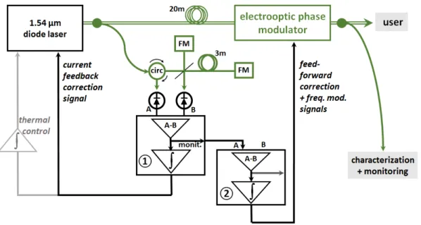
The setup for line narrowing of the DFB diode laser uses a fibre Michelson interferometer with a 3 meter arm imbalance, as shown in Fig. 2. We first present the different components.
Fig. 2. Set-up for spectral narrowing of the DFB diode laser. Green lines: single mode optical fibre.
Double green line: polarization maintaining optical fibre. FM: Faraday mirror. 20m, 3m: fibre spools.
①, ②, electronic gain units for feedback and feed-forward actuation, respectively.
monit.: monitor output of the (A-B) differential amplifier. circ: fibred optical circulator.
Experiments were done with two, nominally 20 mW, identical 3S Photonics DFB diode lasers (model 1905 LMI), at currents ranging from 80 to 125 mA. They showed essentially identical results. These diode lasers include, in
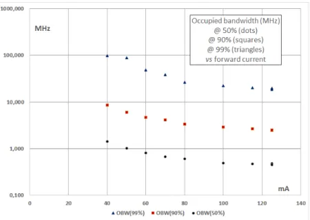
the 14-pin butterfly package, an embedded Peltier cooler and an optical isolator. The laser beam is output through a PM (polarization maintaining) pigtail. The current was fed to pins 3 and 11. To measure the lineshape of the emitted spectrum we use a 1.54 µm Koheras Adjustik fibre laser and beat it with the diode laser beam. The fibre laser provides a ≈ kHz linewidth beam, which can be considered as narrow, compared to the DFB diode laser. The DFB diode laser lineshape changes with the diode laser forward current, and shows significant broadening when the current is lowered towards the threshold. This can be conveniently illustrated by the "occupied bandwidth at P%", i.e. the central optical bandwidth that contains P% of the total optical power. The occupied bandwidths (OBW) at 50%, 90% and 99% are plotted in Fig. 3 below for the free-running DFB diode laser. The OBW at 50% slightly improves from 0.6 to 0.47 MHz when the current is raised from 80 to 125 mA.
Fig. 3. "Occupied bandwidth" of the free-running 3S Photonics DFB laser diode spectrum, at 50%, 90% and
99% of the optical power. The laser threshold is at ≈18mA. Each point is the average over 20 recorded spectra of the beat note between the DFB laser diode and the fibre laser considered as a narrow, reference laser. The current driver is a Vescent Photonics D2-105 controller. Its current noise is specified at 100 pA/√Hz. A servo input allows for addition, to the DC current output, of a correction with a gain of 1 mA/V with a 10 MHz bandwidth. The unit also provides the thermal regulation of the diode (reading of the thermistor value, and control of the diode laser's Peltier cooler). Apart from fitting the diode laser's butterfly package with a large copper slab to evacuate the dissipated power, no particular work has been done as the D2-105 current driver unit allows one to choose from a range of values for the parameters of the temperature control. We do not address thermal issues further but of course it has to be dealt with ("thermal control" in Fig. 2) if uninterrupted operation is to be achieved during long periods of time, as drifts can otherwise give rise to large correction signals to the laser diode current. Two "servo" electronics are required to generate the correction signals:
- an integrator to provide the feedback correction to the diode laser current driver (① in Fig. 2) - an electronics for the feed-forward to the electrooptic phase modulator (②in Fig 2.) As the error signal is a frequency signal, generating the phase correction signal also requires an integrator. But this integrator has to provide correction signals at high frequencies, 100 kHz and above, while integrator ①, that provides the feed-back signal to the diode laser current, operates in the range limited to the feedback loop bandwidth, ≈ 100 kHz.
We use two Newport LB1005 electronics, which have a specified bandwidth of 10 MHz. This model provides two features which are particularly useful for the dual setup: a differential input (which helps to reject possible intensity noise in the DFB laser) and a "Low Frequency Gain Limit" which helps to prevent feeding the electrooptic modulator with large DC signals that could result from offsets. A disadvantage with the LB1005 units is that their transfer function is an integrator only up to a corner above which the response is flat. The highest possible set value of this P-I (proportional-integrator) corner is 1 MHz. As we need a pure integrator well above 10 MHz, we have to correct the transfer function with an appropriately designed RC filter (between ① and ②,
The phase modulator is a Photline MPX-LN-0.1 LiNbO3 PM fibre modulator with 100 MHz bandwidth.
As optical frequency discriminator, we found it very convenient to build a Michelson interferometer with a 50/50 fibre beam splitter and a 3m fibre in one of the two arms. At 1.54 µm, Faraday mirrors (FM in Fig. 2.) provide an inexpensive and convenient solution to the problem associated to the polarization drifts in standard ("single mode") optical fibre. However, Faraday mirrors are available only in the infra-red range, as Faraday materials are increasingly inefficient when going to wavelengths shorter than 1 µ m. If the Michelson interferometer is to be operated at shorter wavelengths, inexpensive gold-coated fibre mirrors can be used in combination with PM (polarization maintaining) fibre to build the Michelson interferometer.
The beat-note between the (free-running or narrowed) DFB laser and the fibre laser is detected by a fast photodiode (EM4, model EM169-03) and spectrally analyzed by an FSP13 Rohde & Schwarz spectrum analyzer. Some features (such as the occupied bandwidth measurement) are particularly convenient for quantitative, real-time monitoring of the beat note spectrum.
III. CHARACTERIZATION OF THE DFB LASER SPECTRUM UNDER FREE-RUNNING AND NARROWING OPERATION
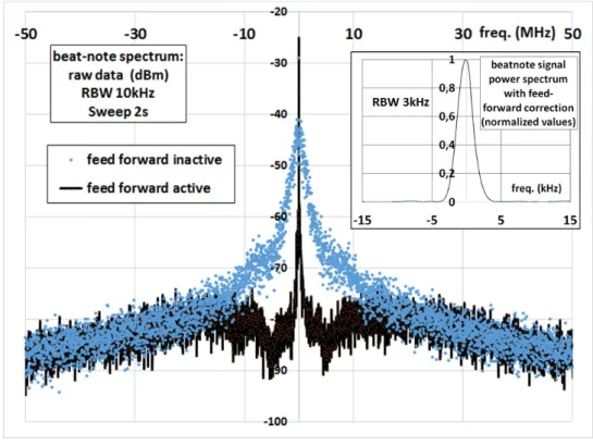
The spectrum of the beat-note signal is quite similar when engaging (or not) the feed-back correction to the current driver. A narrow peak can be observed when the feed-back is engaged with a 100 kHz bandwidth, but the fraction of optical power in the narrow peak is negligible. When the feed-forward correction is active, with the appropriate gain, the spectrum of the DFB laser is affected up to a ≈ 15 MHz bandwidth. In the conditions of Fig. 4. below, the sharp peak (measured in a ±150 kHz interval) contains about 99% of the total optical power. This is in striking contrast with all attempts to implement a double feed-back loop. When implementing a feed back to the current and the phase modulator (Fig. 1.a), even by keeping all connections (fibres, cables) as short as possible, the residual broadband optical power has always been of 15 to 20%, which can be a severe drawback for the user of the narrowed laser source.
Fig. 4. Beat-note signal power spectrum (10 dB/div), with (black lines) or without (blue dots) feed-forward
correction. Inset: central (30 kHz) part of the beat-note spectrum, in linear units.
The fraction of narrowband optical power degrades when the operating current of the DFB laser is lowered, and drops below 99% (Fig. 5 below). This is expected from the measured occupied bandwidth @99% in free-running
operation (Fig. 2): OBW@99% increases from 19 MHz at 125 mA to 26 MHz at 80 mA, already exceeding the ≈15 MHz bandwidth of the feed-forward correction.
Fig. 5. Fraction of narrow-band optical power (measured in the interval [-150kHz,+150kHz]) when the
feed-forward correction is activated, as a function of the DFB diode laser current. The gain of the feed-forward correction is re-adjusted for each value of the current (see Sect. IV below).
The fraction of residual broadband power is one of the two main characteristics of the narrowed laser source. The other is the spectral full width at half maximum, (FWHM) of the laser source. The FWHM has been repeatedly found below 4 kHz (see Fig. 4, inset). Accurate values are difficult to give since our fibre reference laser is neither infinitely narrow, nor ideally stable.
IV. PARTICULAR FEATURES OF THE DUAL, FEED-BACK + FEED-FORWARD METHOD. THE "MONITORING INTERFEROMETER".
First, to achieve efficient narrowing, it is essential to compensate the delay on the electronic feed-forward correction. Equation (2) above assumes that the FF correction signal is synchronous with the frequency noise to be corrected. By summing all the delays in the electronics and cables (to which the main contribution is the ≈50 ns delay in the LB1005 servo unit ②) and in the optical fibre, we found that a ≈20.5 m optical fibre has to be added to the optical path. The spectrum presented in Fig. 4 and the 99% efficiency have been obtained with a 20 m PM fibre spool added before the electrooptical phase modulator. With a fibre spool of only 17 m the residual broadband optical power is three times larger. The delay issue is much easier to deal with in the feed-forward configuration (adding some fibre length) than in the feed-back configuration, in which delay can only lower the lock bandwidth.
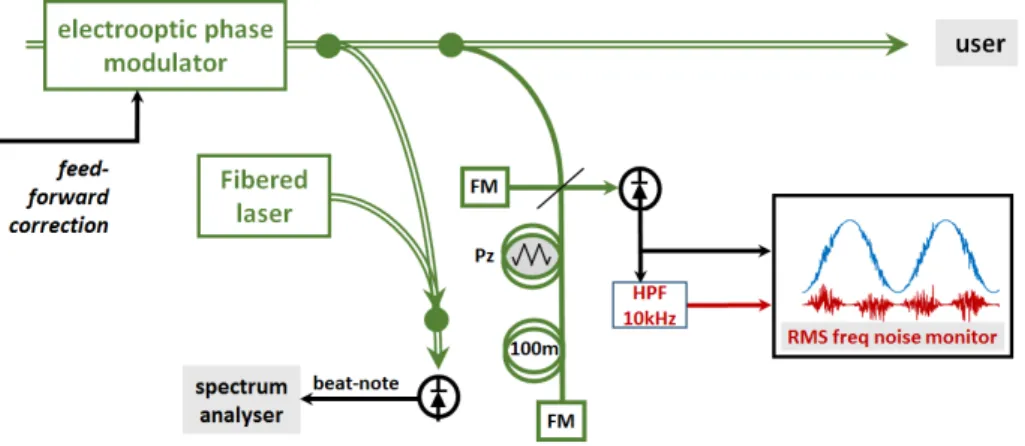
Fig. 6. Characterization of the spectrally narrowed DFB laser source. 100m: long arm fiber roll
for the monitoring interferometer. Pz: piezo-actuated fibre stretcher. HPF: high-pass filter.
Second, the design of a FF correction may seem easy, as it merely consists in implementing a gain such that
1
=
FF
0
1
−
G
FF=
to a high degree of rejection, may be difficult if a reference laser is not available to monitor the resulting narrowing efficiency. We found that the optimal condition remains stable: the gainG
FF does not need to be readjusted every day. However it has to be readjusted as soon as the operating power of the diode laser changes. We implemented a second, "monitor", Michelson interferometer, to help the operator in finding the optimal FF conditions.Compared to the frequency discriminator used to generate the frequency error signal (Fig. 2), the monitor interferometer has a much larger (100 m) arm length difference, and includes a path length modulator (various components can achieve this task -we used an Optiphase PZ1-SMF fibered stretcher), as shown in Fig. 6. We modulate the fiber length with a depth of 2.5 optical wavelengths, at about 12 Hz. Thus we scan 5 fringes of the monitor interferometer signal. When the FF correction is not active, the frequency noise is large enough that the signal of this monitor interferometer spreads over the whole signal range interval (Fig. 7 below, upper graph). When the FF correction is active (Fig. 7, lower graph), the noise on the monitor signal is considerably lowered, so that the five fringes associated to modulation by the fibre stretcher appear. Yet, the frequency noise of the narrowed laser source is still measurable (red trace).
Fig. 7. Upper graph: the monitor interferometer signal when the feed-forward is inactive.
Lower graph: blue points, the same signal when the FF is active, and red: the same signal, high-passed and multiplied by a factor of 2.
To zoom at the residual frequency noise of the spectrally narrowed DFB laser we reject the low frequency part of the fringe signal using a pass RC filter. We have checked that minimizing The RMS noise of this high-passed monitor signal always leads to the optimal narrowing (Fig. 8). This provides a very convenient way to find the optimal gain settings in the servo unit (②) that provides the FF gain.
Fig. 8. Residual fraction of broadband optical power (×10, red triangles) and fractionnal RMS noise (×2) of the
monitoring interferometer signal (blue dot) as a function of the amplitude gain on the FF correction unit. The arrows indicate the points corresponding to the optimum: 0.82% of broadband optical power and
2.2% RMS noise in the monitor interferometer, confirming that the latter allows one to optimise the feed-forward configuration.
V. CONCLUSION
We have achieved high-efficiency spectral narrowing of a DFB diode laser. The setup uses commercial servo units and inexpensive fibre components and requires no particular design (apart from path length equalization). We characterize the spectrally-narrowed laser source by beating the beam with a reference laser. The power in the ±150 kHz interval is about 99% of the total laser power (more than 96% in the ±40 kHz interval). The full width at half maximum is below 4 kHz. The method, which uses a dual, feed-back + feed-forward correction, appears particularly convenient. It can be used at any wavelength provided polarization maintaining fibres and gold-coated fibre mirrors are used whenever Faraday mirrors are not available. The usual approach of the double feed-back (to the current of the laser diode and to the phase modulator) has provided narrowing efficiencies of 80 to 85% at best, in striking contrast with the 99% efficiency obtained when using the dual, feedback + feed-forward correction.
ACKNOWLEDGMENTS.
We thank M. Daldosso and Y. Barje for their contributions to the experiments and F. Kéfélian for help in the simulations of the servo loops. This work has been funded by CNES.
REFERENCES
(*) corresponding author, [email protected]
(◊) now at Laboratoire Géoazur, Sophia-Antipolis, France
[1] D. Gatti et al., “Analysis of the feed-forward method for the referencing of a CW laser to a frequency comb,” Opt. Express, vol. 20, pp. 24880-24885, October 2012.
[2] S. Koke et al., “Direct frequency comb synthesis with arbitrary offset and shot-noise-limited phase noise,” Nat. Photonics vol. 4, pp. 462–465 (2010).
[3] F. Lücking, A. Assion, A. Apolonski, F. Krausz, and G. Steinmeyer, “Long-term carrier-envelope-phase-stable few-cycle pulses by use of the feed-forward method,” Opt. Lett. vol. 37, pp. 2076–2078, June 2012. [4] F. Aflatouni and H. Hashemi, “Wideband tuneable laser phase noise reduction using single sideband