Designed amphiphilic peptide forms stable
nanoweb, slowly releases encapsulated hydrophobic
drug, and accelerates animal hemostasis
The MIT Faculty has made this article openly available. Please share
how this access benefits you. Your story matters.
Citation
Ruan, Liping et al. “Designed amphiphilic peptide forms stable
nanoweb, slowly releases encapsulated hydrophobic drug, and
accelerates animal hemostasis.” Proceedings of the National
Academy of Sciences 106.13 (2009): 5105-5110.
As Published
http://dx.doi.org/10.1073/pnas.0900026106
Publisher
National Academy of Sciences
Version
Final published version
Citable link
http://hdl.handle.net/1721.1/50249
Terms of Use
Article is made available in accordance with the publisher's
policy and may be subject to US copyright law. Please refer to the
publisher's site for terms of use.
Designed amphiphilic peptide forms stable nanoweb,
slowly releases encapsulated hydrophobic drug, and
accelerates animal hemostasis
Liping Ruana, Hangyu Zhanga, Hanlin Luoa, Jingping Liua, Fushan Tanga, Ying-Kang Shib, and Xiaojun Zhaoa,b,c,1
aWest China Hospital Institute for Nanobiomedical Technology and Membrane Biology, West China Hospital and State Key Lab of Biotherapy of Human Diseases, Sichuan University, Science Park 1, Ke Yuan 4th Street, Gao Peng Road, Hi-tech Industrial Development Zone, Chengdu, 610041 Sichuan, China; cCenter for Biomedical Engineering, Massachusetts Institute of Technology, 500 Technology Square, Cambridge, MA 02139-4307; andbWest China Medical School, West China Hospital, Sichuan University, Guo Xue Xiang 37, Chengdu, 610041 Sichuan, China
Communicated by D. Carleton Gajdusek, Centre National de la Recherche Scientifique, Gif-sur-Yvette, France, January 16, 2009 (received for review June 27, 2008)
How do you design a peptide building block to make 2-dimentional nanowebs and 3-dimensional fibrous mats? This question has not been addressed with peptide self-assembling nanomaterials. This article describes a designed 9-residue peptide, N-Pro-Ser-Phe-Cys-Phe-Lys-Phe-Glu-Pro-C, which creates a strong fishnet-like nano-structure depending on the peptide concentrations and mechanical disruptions. This peptide is intramolecularly amphiphilic because of a single pair of ionic residues, Lys and Glu, at one end and nonionic residues, Phe, Cys, and Phe, at the other end. Circular dichroism and Fourier transform infrared spectroscopy analysis demonstrated that this peptide adopts stable-turn and -sheet structures and self-assembles into hierarchically arranged supramolecular aggre-gates in a concentration-dependent fashion, demonstrated by atomic force microscopy and electron microscopy. At high concen-trations, the peptide dominantly self-assembled into globular aggregates that were extensively connected with each other to form ‘‘beads-on-a-thread’’ type nanofibers. These long nanofibers were extensively branched and overlapped to form a self-healing peptide hydrogel consisting of >99% water. This peptide can encapsulate the hydrophobic model drug pyrene and slowly re-lease pyrene from coated microcrystals to liposomes. It can effec-tively stop animal bleeding within 30 s. We proposed a plausible model to interpret the intramolecular amphiphilic self-assembly process and suggest its importance for the future development of new biomaterials for drug delivery and regenerative medicine. -turn/-sheet 兩 hemostasis 兩 nanofibers 兩 hydrogel 兩 self-assembly
D
esign and fabrication of nanoscale biomaterials are critically important for the advancement of biomedical engineering. These include scaffolds for 3D cell and tissue culture, injured tissue repair, and controlled drug release. Biomaterials derived from synthetic or biological polymers have been used extensively for many biomedical applications over decades. Only recently, researchers have attempted to use structural motifs found in nature materials to design and fabricate nanobiomaterials for tissue engineering and regenerative medicine. It is known that many of fibrous proteins and peptides self-assemble into su-pramolecular structures by using-sheet structures, and one of the typical self-assembling peptides is the RADA16-I (1–9), termed as ionic self-complementary peptide. This kind of pep-tide has been designed by mimicking native protein motifs containing regular repeats of alternating oppositely charged residues separated by 1 or 2 hydrophobic residues. These resi-dues interact with each other by at least three major forces: inter-and intramolecular forces such as hydrogen bonding, hydropho-bic, and electrostatic interactions to drive molecular self-assembly process. Because charged amino acids play an impor-tant role in determining peptide molecular assembly through electrostatic interaction and hydrogen bonding, many of the self-assembling biomaterials are designed to containhydropho-bic and hydrophilic residues alternately throughout the entire peptide sequence to ensure a full range of ionic complementarity. However, the full range of ionic self-complementarity does not bend peptide backbones significantly to support 2D nanoweb formation because ‘‘bended backbone’’ helps web formation. For example, RADA16-I forms long and straight nanofibers that stack together to form a porous network without forming apparent nanowebs. In this work, we create nanowebs by using a peptide (N-Pro-Ser-Phe-Cys-Phe-Lys-Phe-Glu-Pro-C) that contains only half-sequence ionic self-complementarity together with turn-making residues of Pro at its termini to generate turns or bended structures, therefore cre-ating self-complementary cohesive or staggering ends for knit-ting and tethering peptide components. At a high concentration, this half-chain complementary peptide could form typical 3D mats or scaffolds with fully packed peptide components. How-ever, after sonication disruption, the 3D mats could be broken down into a ‘‘naked mainframe’’ looking like a knitted fabric in nanoscales (nanowebs). Remarkably, this knitted fabric can be quickly filled up by broken fragments or small-molecular aggre-gates to reform 3D mats through intermediate interwoven fabric. Because of this property, the peptide-formed tensile hydrogel and can self-heal quickly after sonication to cease hemorrhage within minutes. In addition, this peptide was able to encapsulate and slowly release the hydrophobic model drug pyrene as drug carrier. These data suggest a new design concept and method as an alternative way to fabricate biological scaffolds for therapeu-tic applications such as in drug release, tissue repair, and regenerative medicine.
Results
Peptide Design.Extensive studies on many self-assembling pep-tide systems clearly demonstrate that the arrangement pattern of ionic-complementary residue pairs along the entire peptide chain or sequence is very important for peptide self-assembling into nanofibers. For example, RADA16-I contains 4 ionic-complementary pairs of residues, and each pair is exactly separated by 1 Ala to reduce intramolecular interference. This type of configuration has been widely adopted over a decade, and many peptide-derived biomaterials have been fabricated according to this rule. In this work, we report a design of the peptide N-Pro-Ser-Phe-Cys-Phe-Lys-Phe-Glu-Pro-C [ support-ing information (SI) Fig. S1] inspired by a recent report (10), Author contributions: L.R. and X.Z. designed research; L.R., H.Z., H.L., J.L., and F.T. per-formed research; Y.-K.S. and X.Z. contributed new reagents/analytic tools; L.R., H.Z., H.L., J.L., F.T., and X.Z. analyzed data; and L.R. and X.Z. wrote the paper.
The authors declare no conflict of interest.
1To whom correspondence should be addressed. E-mail: xiaojunz@mit.edu.
This article contains supporting information online atwww.pnas.org/cgi/content/full/ 0900026106/DCSupplemental.
which contains only one pair of ionic-complementary residues Lys and Glu at one end and nonionic residues at the other end. Specifically, we have chosen two structurally distinguishable elements: one is composed of two oppositely charged residues, Glu and Lys, to generate electrostatic attraction in an antipar-allel strand orientation; the second element contains the key residues Phe-Cys-Phe as the hydrophobic module. We also used Ser to improve local solubility because Ser is a mild -sheet breaker, and it may interfere with the -sheet stability. To reduce the hydrogen-bonding network in the-sheet structure at the strand ends, we used 1 Pro residue at the N and C termini because Pro does not have N-H moieties available for hydrogen bonding by virtue of its ring structure, often acting as-sheet breaker (10–11). In addition, the proline can reduce -sheet expansion and extra fibril formation by stopping extension of the hydrogen-bonding network and can bend the peptide chain by forming turns, allowing interfiber staggering and tethering.
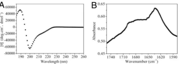
Secondary Structure of the Designed Peptide. We used circular dichroism (CD) and Fourier transform infrared (FTIR) spec-troscopy to characterize the secondary structure of the peptide. The CD analysis at 25 °C showed a negative maximum⬇200 nm ([]200 ⫽ ⫺65,000° per cm2䡠dmol⫺1) and a positive maximum
near 189 nm ([]189⫽ 52,000° per cm2䡠dmol⫺1) (Fig. 1A), the
characteristics of a-turn structure (12). There is also a weak peak at a wavelength of ⬇213 nm ([]213 ⫽ ⫺20,000° per
cm2䡠dmol⫺1), which indicated a-sheet structure. This spectrum
does not perfectly match that of a typical-sheet (3), possibly because of the influence of a-turn structure. To investigate it further, we used the program CD Pro to analyze the secondary structure content by comparison with 50 reference proteins, including 37 soluble proteins and 13 membrane proteins; the calculation showed that our peptide has a high content of -strand and turn at 36.5% and 38.7%, respectively, strongly supporting the experimental data. To validate the CD data further, we used FTIR spectroscopy (13–16) to determine the secondary structure of the peptide. Fig. 1B shows the spectra of the peptide within the wave numbers of 1,580 and 1,750 cm⫺1. As shown within these wave numbers, the amide I band (1,600– 1,700 cm⫺1) region is mainly the result of CAO stretching vibration but to a lesser extent CON stretching vibration of the peptide bonds in response to the secondary structure of the peptides. The peak between 1,620 and 1,640 cm⫺1is attributed to the formation of -sheet structures, whereas the peaks at ⬇1,675 cm⫺1 and a high-frequency peak at ⬇1,690 cm⫺1 are
attributed to the formation of-turn structures such as ‘‘hair-pins’’ (17, 18). We analyzed the amide I band (Fig. 1B) and could distinguish three peaks located at 1,633, 1,675 and 1,696 cm⫺1. The lowest one (1,633 cm⫺1) is assigned to intermolecular
-sheets resulting from aggregation, whereas the band at 1,675 and 1,696 cm⫺1 indicates the presence of a -turn structure. Based on these CD and FTIR data, we believe that the peptide contains both-turn and -sheet structures. Furthermore, many amino acids such as Asp, Ser, Glu, and Pro are most frequently associated with -turns, and their presence in the peptide possibly contributes to the formation of-turn structure.
Rheological Properties.We carried out frequency sweep experi-ments at 25 °C and found that the value of the storage modulus G⬘ in the peptide solution was larger than the value of the loss modulus G⬙. It is known that storage modulus G⬘ measures elastic responses of materials, and the loss modulus G⬙ measures the viscous response. Our data clearly indicated that the peptide nanofiber solution behaved as an elastic gel (Fig. 2A). To confirm its elastic property further, we treated the peptide solution with a constant strain of 1,000% at 6 Hz for 180 s and found that the treated gel/solution underwent typical shear thinning behavior as did other polymer gels (Fig. 2B) (19) because the gel volume or viscosity dropped under stress con-ditions due to the disruption of physical cross-linking or molec-ular overlapping/interpenetration. It usually takes a relatively long time for polymer gels to recover after shear strains, and often the polymer gels are unable to recover back after stress relaxation because of their inability to start repolymerization in the absence of reaction initiators. In contrast, our peptide solutions quickly reformed into gels after a 30-min stress relax-ation and reached the original rigidity, indicating a strong self-healing material property (Fig. 2B).
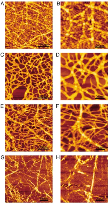
Morphological Study by Atomic Force Microscopy (AFM).The peptide only contained a single pair of ionic-complementary residues, but its half-chain ionic complementarity was still able to support nanofiber formation (Fig. 3). Interestingly, the peptide fiber showed very different morphology compared with the morphol-ogy of the RADA16-I fibers (4, 5). Specifically, the peptide fibers in our work were composed of many globular aggregates that were connected with each other in a ‘‘beads-on-a-thread’’ fash-ion and further piled up into 3D aggregated network. The peptide fibers were 86.51⫾ 10.61 nm wide and 5.72 ⫾ 1.25 nm high. In addition, the fibers were not straight but instead had branching network structures containing many branching nodes, which differed from the fibers of the RADA16-I, suggesting that the coexistence of both-turn and -sheet structures helps form globular aggregations and a massively interwoven network.
Different Morphology of the Peptide in Aqueous Solution.The AFM images with a scale of 2⫻ 2m2and 1⫻ 1m2are shown in Fig. 1. Secondary structures of the peptide. (A) CD spectrum of the peptide
(200M) at 25 °C in the Milli-Q water. The spectrum shows a negative maximum⬇200 nm ([]200⫽ ⫺65,000° per cm2䡠dmol⫺1) and a positive maxi-mum near 189 nm ([]189⫽ 52,000° per cm2䡠dmol⫺1), the characteristics of a -turn structure. (B) FTIR spectrum for the peptide at 10 mg/mL. The peptide has a peak centered at⬇1,633 cm⫺1, and this peak is attributed to the formation of sheet structure. The other two broad peaks are located at⬇1,675 and 1,696 cm⫺1, characteristics of the-turn structure.
Fig. 2. Rheology of the peptide solution at 10 mg/mL. (A) Frequency sweep (1-Pa shear stress) of 1% peptide at 25 °C.■, storage moduli;Œ, loss moduli. The frequency sweep results measured at 25 °C revealed that storage modulus of the peptide (G⬘, a measure of the elastic response of the material) was larger than loss modulus (G⬙, a measure of the viscous response) over all measured frequencies. (B) Restoration of gel as a function of time followed by the cessation of treatment for gel network destruction (1,000% strain at 6 Hz for 180 s).■, storage moduli;Œ, loss moduli. The peptide showed its strong self-assembling ability to reform the gel quickly.
Fig. 4. The peptide was able to self-assemble into nanofibers, and the fiber morphologies diversified when the peptide concentra-tions were changed. At the highest concentration of 1.0 mg/mL, the peptides aggregated as the globular beads that were well lined up to form larger-sized nanofibers in a way similar to beads on a thread in Fig. 4 A and B. When the concentration was decreased to 0.5 mg/mL, the fibers became much smaller, 23.7 nm wide and 1.0 nm high, containing many large-sized meshes (Fig. 4 C and D). When the concentration was decreased further to 0.3 mg/mL, the fibers became progressively smoother without much of the beads-on-a-thread morphology with large-sized meshes (Fig. 4 E and F). The smooth and thin fibers were further observed with transmission electron microscopy (TEM). These fibers were connected with each other to form an interwoven network at concentration of⬇0.1 mg/mL observed by AFM (Fig. 4 G and H) and by TEM with a low magnification (25,000-fold) in Fig. 5A. At high magnification (60,000-fold; Fig. 5B), these thin fibers were twisted into ribbon-like forms in a highly organized way.
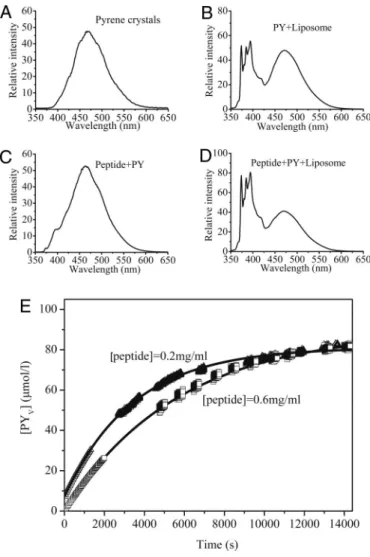
Potential Carrier of Hydrophobic Compounds.Many drugs are in-soluble in water and need an appropriate vehicle to deliver them to target cells within tissues. Because the peptide contains both hydrophobic and hydrophilic segments, we hypothesized that it could interact with the hydrophobic cargo and still have a good solubility in aqueous solution. Previous work showed that pyrene can be a good hydrophobic model drug because of its low water solubility (⬇6 ⫻ 10⫺7M), well-defined fluorescence spectra, and well-established method to statistically analyze the transfer rate of pyrene into liposome vesicles (20–25). We therefore used this system to measure our peptide-mediated delivery of pyrene into liposomes. We mixed the peptide with pyrene and observed a massive formation of pyrene microcrystals in a suspended solution, indicating a large amount of pyrene in association with the peptides (Fig. S2 Right). However, the pyrene crystals in pure water did not form any suspensions; instead, they just remained floating on the liquid surface or sank to the bottom (Fig. S2 Left). Pyrene in pure water exhibited maximum fluorescence intensity at⬇470 nm as excimer with no visible pyrene monomer emission (Fig. 6A), and the peptide–pyrene (peptide–PY) solution dis-placed almost an identical pattern at the same wavelengths, indicating that the peptide stabilizes pyrene crystalline in solu-tion without breaking its crystalline into dispersed monomers (Fig. 6 A and C). We then mixed the peptide–PY solution with soybean lecithin (SL) liposome vesicles and tested whether the pyrene encapsulated by the peptide could be transferred into membrane bilayers made of the SL liposomes. The steady-state fluorescence spectra demonstrated that the spectrum of the peptide–PY solution mixed with the liposome vesicles (Fig. 6D) was similar to the spectrum of pyrene in liposome vesicles alone (Fig. 6B). Pyrene has different peak signals between 360 and 400 nm depending on solvent polarity. The defined II/IIII emission intensity was used as a scale for solvent polarity. When pyrene
is present in a polar solvent such as water, the II/IIIIratio equals 1.7; when pyrene is present in lipid-like environment such as egg phosphatidylcholine liposomes, the II/IIII ratio equals 1.1. By measuring II/IIII ratio, we could determine the environments containing pyrene. Our data indicated that the II/IIIIratio (374 nm/385 nm) for both pyrene in SL liposome vesicles and peptide–PY solution mixed with SL liposome vesicles all equaled 1.02 with no difference in a good agreement with II/IIIIratio of 1.1 in lipid vesicles. These data suggest that pyrene encapsulated by the peptide has been directly transferred from the peptide–Py complex into hydrophobic vesicle membrane bilayers and that
Fig. 3. Typical AFM morphological images of the peptide deposited on mica. (A) Peptide dissolved in water at 1 mg/mL. The image shows beads-on-a-thread fibers in a branched network. These fibers are made of many globular aggregates lining up and stacking together. (B) Higher magnification of A; a staggered arrangement of globular aggregates is observed. (C) Higher mag-nification of B. The scales are marked in each panel.
Fig. 4. AFM images at different peptide concentrations. (A) At 1 mg/mL, showing globular structure fibers and many small fibers in the background. (B) Higher magnification of A, showing details of the background with small fibers and small globular structures. (C and D) At 0.5 mg/mL, showing little globular structures along the fibers. (E and F) At 0.3 mg/mL, showing many small fibers and some wider fibers twisted together with the smaller ones. (G and H) At 0.1 mg/mL, showing many small fiber and narrow fibers. The scales are marked in each panel.
this transfer is a time-dependent release process (Fig. 6E). Further analysis of kinetic behavior of pyrene transfer from the pep–PY complex to the liposome vesicles indicated a time-dependent release of pyrene molecules from the peptide–PY solution into the vesicles. The initial rate of pyrene release from the peptide-coated pyrene crystals appeared to occur much more slowly for the peptide 06–PY (the peptide concentration at 0.6 mg/mL) solution than for the peptide 02–PY (the peptide concentration at 0.2 mg/mL) solution although the final pyrene concentrations in the liposome vesicles reached similar values (Fig. 6E). The data demonstrated that this amphiphilic peptide can stabilize a hydrophobic cargo in aqueous solution and subsequently deliver pyrene into a lipophilic membrane-mimicking device. The rate of pyrene release can be controlled by adjusting the peptide/pyrene ratio.
Hemostatic Effect of Self-Assembly Peptide.Previous experiments showed that some peptides forming fibers or hydrogel can be used for tissue repair and wound healing (1, 2, 5). In this work, we have tested whether our peptide components can stop bleeding. To ensure data consistence, we chose the left lateral lobe of the rat liver to create an injured surface. Specifically, we cut the lower portion of the left lateral lobe of the liver via a 2-cm incision to create a grade II wound surface because such wounds show more blood loss than wounds from a sharp instrument. Using this model, we found that the peptide was able to stop bleeding within a significantly shorter time compared with other hemostatic materials (Table 1). For example, the hemostatic mean time in the 1% peptide group was equal to 13% of that in the gauze group (P⬍ 0.001) and 19% of that in the chitosan group (P ⬍ 0.001). In the other words, the peptide required ⬍20% of the time required for the other materials to achieve full hemostasis. These data indicated that the hydrogel assembled by the peptides is one of the most promising nanomaterials for hemostasis and that it can be potentially developed for future clinical hemostasis applications.
Discussion
-Turn Structure.This 9-residue peptide (Pro-Ser-Phe-Cys-Phe-Lys-Phe-Glu-Pro) contains a-turn structure. To determine the role of residues Ser and Glu, we replaced Ser with Thr to generate mutant peptide P1 (Pro-Thr-Phe-Cys-Phe-Lys-Phe-Glu-Pro) and replaced Glu with Asp to generate mutant peptide P2 (Pro-Ser-Phe-Cys-Phe-Lys-Phe-Asp-Pro). Replacement of Ser did not affect the structures of the-turn and fiber-network formation (Figs. S3aandS4a). In contrast, P2 decreases-turn content and forms much shorter fibers and less-branched net-work (Figs. S3bandS4b). These data suggest that Glu is required
for -turn and branched-network formation. The turn is re-ported to possibly adopt a hairpin structure that may participate in the peptide assembly in many ways (Fig. S5). For example, the peptide monomers adopting a hairpin structure can form
glob-Fig. 5. TEM images of the peptide at 0.2 mg/mL. (A) Low magnification (25,000-fold), showing high-density fiber networks. (B) Higher magnification (60,000-fold) for a single fiber, and the fibrils were twisted together to form fibers. The scales are marked in each panel.
Fig. 6. Steady-state fluorescence emission spectra. (A–D) Solid pyrene crys-tals (A) and pyrene in soybean lecithin liposome vesicles (B) ([PY]⫽ 9.6 ⫻ 10⫺5 M; [liposome]⫽ 1.59 ⫻ 10⫺3M). (C) Peptide–PY solution ([PY]⫽ 1.98 ⫻ 10⫺3 M; [peptide]⫽ 1.75 ⫻ 10⫺4M), showing a spectrum similar to A. (D) Pep-tide–PY solution mixed with liposome vesicles ([PY]⫽ 6.6 ⫻ 10⫺5M ; [peptide] ⫽ 5.83 ⫻ 10⫺6M; [liposome]⫽ 1.59 ⫻ 10⫺ 3M),ex⫽ 336 nm, showing spectrum similar to B. (E) Fluorescence curves for the release of molecular pyrene from pyrene microcrystals encapsulated in the peptide coating into bilayers of soybean lecithin liposome ([liposome]⫽ 1.59 ⫻ 10⫺3M).䊐and‚, pyrene transfer experiments carried out with peptide 06 –PY and peptide 02–PY, respectively.
Table 1. Hemostatic effects of different hemostatic agents in rats Hemostatic agents No. of experimental animals Bleeding time, s Gauze 10 120⫾ 31*** 1% Chitosan 10 84⫾ 26*** 1% Peptide 10 16⫾ 6
The peptide at 1% concentration was compared with the gauze group and the chitosan group, and mean values⫾ SEM are shown. ***, P ⬍ 0.001. The P value⬍ 0.05 suggests that the difference in the time of hemostasis treated with hemostatic agents has statistical significance with a confidence level of 95%.
ular aggregates or beads that either bind directly to long fibers to form beads-on-a-thread structures or serve directly as branch-ing points in the growbranch-ing fibers (Fig. S5). These data demon-strate that the -turn motif can be used as one of the most powerful design elements in nanostructure fabrication. Combin-ing both -turn and -sheet elements can broaden design concepts and create more diversified biomaterials.
Dynamic Reassembly of Peptide Nanofibers. To study molecular mechanism further, we measured reassembly dynamics. The peptide solution was sonicated for 5 min with 800-W output power (the diameter of the probe was 2 mm), and the samples were deposited immediately onto a freshly cleaved mica surface at varying times after sonication (Fig. S6). The fibers have been broken into small fragments, including globular aggregates immediately after sonication, but the peptide-formed network still maintains its mainframes containing many large-sized meshes irrespective of the output power used (Fig. S6b). Within 48 h, most of the meshes have been filled up by the peptides or aggregates (Fig. S6c), indicating a dynamic process of disassem-bly and reassemdisassem-bly. It seems that the mainframe structure serves as ‘‘nucleation seeds’’ to take up or absorb those broken peptide fragments or globular beads to reassemble rapidly into fibers and sheets (Fig. S6c). This behavior strongly differs from other peptide systems possibly because of coexistence of both-turn and -sheet elements that stabilize mainframes by massively branched and interwoven network at many nodes tethered together.
Design Principles in Biomaterials Fabrication and Application. Our data show that the designed peptide containing intramolecular half-chain ionic complementary sequence is able to form both -turn and -sheet structures. Combining these secondary struc-ture elements could produce many strong-branched and tethered nanofibers in a network, therefore broadening our design pat-terns and making diversified nanomaterials for future therapeu-tic applications.
Experimental Procedures
Materials. Peptides used in this study were synthesized from Chengdu CP
Biochem Co., stored at⫺20 °C, and used without further purification. The amino acid sequence of the peptide was CH3CO-Pro-Ser-Phe-Cys-Phe-Lys-Phe-Glu-Pro-NH2(molecular weight 1,142, purity 95%), and the N and C termini were protected by acetyl and amino groups, respectively. The amino acid sequence of mutated peptides were CH3CO-Pro-Thr-Phe-Cys-Phe-Lys-Phe-Glu-Pro-NH2(molecular weight 1,156, purity 95%, named as P1), and CH3CO-Pro-Ser-Phe-Cys-Phe-Lys-Phe-Asp-Pro-NH2(molecular weight 1,128, purity 95%, named as P2), respectively. The N and C termini of all of the designed peptides were protected by acetyl and amino groups, respectively. All of the peptides were synthesized by using standard Fmoc solid-phase chemistry. Peptide homogeneity and composition were analyzed by analytical HPLC and mass spectrometry. Peptide stock solutions were prepared at a concentration of 10 mg/mL (1% wt/vol) in water (18.2 M⍀, Mill-Q; Millipore) and stored at 4 °C before use.
CD Spectroscopy. CD data were gathered at 25 °C on an AVIV model 400
spectrometer (AVIV Associates), by using a 1-mm path length quartz cuvette. Spectra were collected at 1-nm intervals and 1-nm bandwidth from 185 to 260 nm with 1-s signal averaging time, with three-times scans for averaging. All spectra were corrected by subtracting the baseline, and the data were ex-pressed as mean residue ellipticity, [], which was given in the units of degrees per cm2䡠dmol⫺1. The peptide samples with a concentration of⬇0.23 mg/mL in Milli-Q water were incubated at 4 °C for 2 days before testing.
To investigate the secondary structures of the peptides fully, the free software CDPro (http://lamar.colostate.edu/sreeram/CDPro/main.html) was used to estimate secondary-structure contents. The secondary-structure frac-tions of the peptides were calculated by the modified Contin method (CON-TINLL program) with comparison with a selected set of reference proteins.
FTIR Spectroscopy. FTIR spectroscopies were measured on a PerkinElmer
spec-trum. One FTIR spectrometer with a wave number resolution of 4 cm⫺1was used under a nitrogen atmosphere. The peptide solution (10 mg/mL,⬇10L)
was deposited onto a crystal slide of zinc selenide (ZnSe) and dried at room temperature. The baseline was subtracted from the obtained absorbance intensity.
Rheology Properties. Rheology experiments of the gels were performed at
25 °C on a rheometer (HAAKE Rheostress I) with a cone and plate geometry system (cone diameter 2 cm, angle 1°, truncation 51m). An aliquot of 100 L of peptide solution was placed on the plate. After removing excess solution, the cone was lowered, and eventually the tip was 51m above the plate. Stress sweeps were performed from 0.1 to 10 Pa to determine the limit of linear viscoelastic region of the samples. At a constant shear stress of 1 Pa, chosen from the linear viscoelastic (LVE), frequency sweeps ranging from 100 to 0.1 rad/s were performed. Shear recovery experiments were performed after destructing the gel network with 1,000% strain at 6 Hz for 180 s, followed by a time sweep experiment at constant shear stress of 1 Pa and constant frequency of 6 rad/s for 30 min. Temperature control was provided with a temperature regulated circulating water bath (HAAKE Phoenix II).
AFM. AFM was used to obtain the nanostructure of the peptide. The peptide
stock solutions (1% wt/vol) were diluted to different concentrations with 18 M⍀ conductivity water (Milli-Q; Millipore Corp). An aliquot of 5L of the peptide solution was placed evenly onto a freshly cleaved mica surface. Each sample was left on the mica surface for⬇30 s. The surface was then rinsed with 200L of water to remove unattached peptide. The samples were covered with Petri dishes to avoid contamination and air-dried for AFM observation. AFM was performed at room temperature by using the tapping mode on a SPI4000 probe station and SPA-400 SPM unit (Seiko Instruments). All images were collected by using a 20-m scanner (400) and an Olympus Si-DF20 cantilever and a Si tip of radius 10 nm at spring constant of 12.00 N/m, with a resonance frequency of 127.00 kHz. All of the measurements were performed in ambient air, and height images were recorded with 512-⫻ 512-pixel resolution. For each sample, images were scanned and collected at scales of 5⫻ 5m2, 2⫻ 2m2, and 1⫻ 1m2.
TEM. TEM was performed at room temperature with a Hitachi H-600 electron
microscope at 100-kV accelerating voltage. The peptide solution (1% wt/vol) was made by diluting the peptide stock solutions to concentration of 0.2 mg/mL with water. A droplet (⬇20L) of peptide solution was deposited on a clean surface. Then a copper EM grid coated with a polyvinylformal mem-brane was immersed into the droplet for 15 s. The excess liquid on the grid was removed with filter paper. The attached peptide on the grid was then nega-tively stained with phosphotungstic acid solution (1% wt/vol in water) for⬇15 s and air-dried for TEM observation.
Hydrophobic Compounds Carrier. SL liposomes were prepared by the
film-ultrasonic method (24). The solution mixed with the peptide and PY crystals was prepared by placing weighed amounts of the peptide and PY in a 20-mL vial and was dissolved in water to obtain concentrations of 0.4 mg/mL (1.98⫻ 10⫺3M) for pyrene and 0.2 mg/mL (1.75⫻ 10⫺4M) and 0.6 mg/mL (5.25⫻ 10⫺4 M) for the peptide to obtain the peptide 02–PY and peptide 06 –PY solutions. Peptide–PY was sonicated for several minutes in a bath-type sonicator at room temperature and was kept on a stirrer plate until it was stable. Peptide–PY was deemed to be stable when its fluorescence spectrum did not change in 72 h. Fluorescence spectrum measurements were performed at room tempera-ture by using a Hitachi F-4500 spectrophotometer with a stirring accessory. The spectra of all solutions were obtained with a 10-mm path length quartz cuvette. The spectra of pyrene crystals were recorded by using a solid acces-sory. For emission spectra, the following parameters were used in all experi-ments (except where stated otherwise): excitation wavelength (ex) 336 nm; excitation slit width 10 nm, emission slit width 2.5 nm, scan speed 240 nm/min; response time 0.5 s, emission spectra range 340 – 650 nm. Excitation spectra were recorded at selected emission wavelengths (373 nm), with excitation and emission slit widths of 5.0 nm and scan speed of 240 nm/min. To obtain kinetic information for the transfer of pyrene from peptide–PY to the liposome, an appropriate volume of peptide–PY was added to the bottom of the quartz cuvette and mixed with 3 mL of liposome solution by using a small magnetic stirrer. Then, Imwas recorded at 373 nm over 4 h at intervals.
Hemostatic Experiment. The regulations and policies of the Animal Ethics
Committee of Sichuan University were followed carefully during experiments in the animal facility units and in laboratories. Female Sprague–Dawley rats weighing between 190 and 300 g were used in this work. All animals were purchased from the Center of Laboratory Animals of the School of Clinical Medicine of Sichuan University, and the surgery was accomplished at this Center. All animals were given postoperative ampicillin– cloxacillin at a dose
of 50 mg/kg of body weight once daily for 3 days as intramuscular injections. Euthanasia of animals was done by giving them an anesthetic dose following the guidelines of the Animal Care and Use Committee of Sichuan University. Rats were divided into 3 groups according to different hemostatic treat-ments as follows.
Gauze group (nⴝ 10, as control 1). A portion of liver tissue was cut, and the wound was allowed to bleed freely for 10 s without wiping away blood from the injured surface. Then, the gauze was applied to the injured surface and was gently pressed manually for 20 s. Then the injured surface was observed for 10 s. If the bleeding continued or occurred again during this 10-s period, a next hemostasis cycle was carried out until hemostasis was achieved. If the total time of hemostasis process was⬎10 min, the hemostasis was judged to be failed.
Chitosan (1% wt/vol) group (nⴝ 10, as control 2). A portion of liver tissue was cut, and the wound was allowed to bleed freely for 10 s without wiping away
blood from the injured surface. Then, 50L of chitosan solution (1% wt/vol) was injected evenly into the wound by using a 100-L pipette, and gauze was used to collect the outflow of blood until hemostasis was achieved.
Peptide (1% wt/vol) group (nⴝ 10, for the experiment). A portion of liver tissue was cut, and the wound was allowed to bleed freely for 10 s without wiping away blood from the injured surface. Then, 50L of the peptide solution (1% wt/vol) was injected evenly into the wound by using a 100-L pipette, and gauze was used to collect the outflow of blood until hemostasis was achieved.
ACKNOWLEDGMENTS. We thank Professor Shuguang Zhang of MIT for his
helpful discussion and Dr. Jon Kornhauser for his critical reading of this manuscript. This work was supported in part by the 985 Project of Sichuan University of Ministry of Education of China.
1. Zhang S, Holmes T, Lockshin C, Rich A (1993) Spontaneous assembly of a self-complementary oligopeptide to form a stable macroscopic membrane. Proc Natl Acad
Sci USA 90:3334 –3338.
2. Zhang S, Gelain F, Zhao X (2005) Designer self-assembling peptide nanofiber scaffolds for 3D tissue cell cultures. Semin Cancer Biol 15:413– 420.
3. Zhao X, Zhang S (2006) Self-assembling nanopeptides become a type of biomaterial.
Adv Polym Sci 203:145–170.
4. Zhang S (2003) Building from the bottom up. Materials Today 6:20 –27.
5. Yokoi H, Kinoshita T, Zhang S (2005) Dynamic reassembly of peptide RADA16-I nano-fiber scaffold. Proc Natl Acad Sci USA 102:8414 – 8419.
6. Holmes TC, et al. (2000) Extensive neurite outgrowth and active synapse formation on self-assembling peptide scaffolds. Proc Natl Acad Sci USA 97:6728 – 6733. 7. Zhao X, et al. (2006) Designer short peptide surfactants stabilize G protein-coupled
receptor bovine rhodopsin. Proc Natl Acad Sci USA 103:17707–17712.
8. Zhang S, Altman M (1999) Peptide self-assembly in functional polymer science and engineering. React Funct Polym 41:91–102.
9. Caplan MR, Moore PN, Zhang S, Kamm RD, Lauffenburger DA (2000) Self-assembly of a-sheet governed by relief of electrostatic repulsion relative to van der Waals attraction. Biomacromolecules 1:627– 631.
10. Sneer R, Weygand MJ, Kjaer K, Tirrell DA, Rapaport H (2004) Parallel-sheet assemblies at interfaces. ChemPhys Chem 5:747–750.
11. Matsumura S, Uemura S, Mihara H (2004) Fabrication of nanofibers with uniform morphology by self-assembly of designed peptides. Chem Eur J 10:2789 –2794. 12. Sanyal G, et al. (1995) Spectroscopic characterization of tick anticoagulant peptide.
Biochim Biophys Acta 1249:100 –108.
13. Byler DM, Susi H (1986) Examination of the secondary structure of proteins by decon-volved FTIR spectra. Biopolymers 25:469 – 487.
14. Remondetto GE, Subirade M (2003) Molecular mechanisms of Fe2⫹-induced -lacto-globulin cold gelation. Biopolymers 69:461– 469.
15. Gilbert V, et al. (2005) Characterization and evaluation of whey protein-based biofilms as substrates for in vitro cell cultures. Biomaterials 26:7471–7480.
16. Lefe`vre T, Subirade M (2000) Molecular differences in the formation and structure of fine-stranded and particulate-lactoglobulin gels. Biopolymers 54:578–586. 17. Surewicz WK, Mantsch HH (1988) New insight into protein secondary structure from
resolution-enhanced infrared spectra. Biochim Biophys Acta 952:115–130. 18. Jun S, et al. (2004) Self-assembly of the ionic peptide EAK16: The effect of charge
distributions on self-assembly. Biophys J 87:1249 –1259.
19. Schneider JP, et al. (2002) Responsive hydrogels from the intramolecular folding and self-assembly of a designed peptide. J Am Chem Soc 124:15030 –15037.
20. Alakhov VY, Moskaleva EY, Batrakova EV, Kabanov AV (1996) Hypersensitization of multidrug resistant human ovarian carcinoma cells by pluronic P85 block copolymer.
Bioconjugate Chem 7:209 –216.
21. Allen CA, Yu Y, Maysinger D, Eisenberg A (1998) Polycaprolactone-b-poly (ethylene oxide) block copolymer micelles as a novel drug delivery vehicle for neurotrophic agents FK506 and L-685,818. Bioconjugate Chem 9:564 –572.
22. Chiu HC, Chern CS, Lee CK, Chang HF (1998) Synthesis and characterization of am-phiphilic poly(ethylene glycol) graft copolymers and their potential application as drug carriers. Polymer 39:1609 –1616.
23. Liaw J, Aoyagi T, Kataoka K, Sakurai Y, Okano T (1998) Visualization of PEO-PBLA-pyrene polymeric micelles by atomic force microscopy. Pharm Res 15:1721–1726. 24. Keyes-Baig C, Duhamel J, Fung SY, Bezaire J, Chen P (2004) Self-assembling peptides as
a potential carrier of hydrophobic compounds. J Am Chem Soc 126:7522–7532. 25. Kwon GS, et al. (1994) Block copolymer micelles as vehicles for hydrophobic drugs.
Colloids Surfaces B 2:429 – 434.