A Distributed Processing Network for
Autonomous Micro-rover Control
by Charles P. Tung
Submitted to the Department of Electrical Engineering and Computer Science in Partial Fulfillment of the Requirements for the Degrees of
Bachelor of Science in Electrical Science and Engineering Bachelor of Science in Mechanical Engineering
and Master of Engineering in Electrical Engineering and Computer Science at the Massachusetts Institute of Technology
January 15, 1998
Copyright 1998 Charles P. Tung. All rights reserved. The author hereby grants M.I.T. permission to reproduce and distribute publicly paper and electronic copies of this
thesis and to grant others the right to do so.
Author
Department f Electrical Engineering and omputer Science January 15, 1998 Certified by
, lavid Kang
T" Supert_ _
Certified by Gill Pratt
SSpervisor Accepted b
Ace"db Arthur C. Smith Chairman, Department Committee on Graduate Theses
A Distributed Processing Network for Autonomous Micro-rover Control
by Charles P. Tung Submitted to the
Department of Electrical Engineering and Computer Science January 20, 1998
In Partial Fulfillment of the Requirements for the Degree of Bachelor of Science in Electrical Science and Engineering
Bachelor of Science in Mechanical Engineering
and Master of Engineering in Electrical Engineering and Computer Science
ABSTRACT
Clearing unexploded ordnance (UXO) is currently a dangerous and slow process that exposes personnel and equipment to considerable risk. The EOD family of micro-rovers developed at the Charles Stark Draper Laboratory, was designed as an alternative method for UXO detection and retrieval that would minimize the risk of human injury. The EOD micro-rovers are 6-wheel, flexible frame, autonomous micro-rovers with an UXO detection sensor, and a 2 DOF grappler assembly. The EOD approach to UXO clearing would allow a single operator to perform the tasks that previously required a highly trained team of personnel to complete. This paper includes a technical description of the EOD family of micro-rovers. Testing of the EOD micro-rovers uncovered areas that could be improved in future implementations of autonomous robots. Specifically, distribution of the on-board processing and the implementation of a serial bus network could drastically improve the micro-rover's performance while reducing the time and cost to manufacture.
Thesis Supervisor: David Kang
Acknowledgement
This thesis was prepared at The Charles Stark Draper Laboratory, Inc., under Internal Research and Development Funding.
Publication of this thesis does not constitute approval by Draper or the sponsoring agency of the findings or conclusions contained herein. It is published for the exchange and
stimulation of ideas.
I hereby assign my copyright of this thesis to the Charles Stark Draper Laboratory, Inc., Cambridge, Massachusetts.
>' Oarles Tung
Permission is hereby granted by The Charles Stark Draper Laboratory, Inc. to the Massachusetts Institute of Technology to reproduce any or all of this thesis.
TABLE OF CONTENTS
1 Introduction... 8
1.1 Autonomous Robotics ... 8
1.2 Applications for Autonomous Robots ... ... 8
1.3 M icro-rovers ... 9
1.4 Intelligent Unmanned Vehicle Center ... 9
2 The EOD Architecture ... 11
2.1 Mechanical Design ... 11
2.1.1 Flexible Frame and Modular Chassis ... 11
2.1.2 Drive Train ... 12
2.1.3 Steering System... 12
2.1.4 Grappler Mechanism ... 13
2.2 Main Processor Stack ... ... 13
2.2.1 Little Giant Microcontroller ... 14
2.2.2 PIO096 Digital I/O Expander... ... 15
2.3 Sensors and Actuators ... ... 16
2.3.1 Sonar Rangefinder...16
2.3.2 Gyro Integration Module... ... 18
2.3.2.1 Micro-mechanical rate gyro ... ... 19
2.3.2.2 Anti-aliasing filter... ... 19
2.3.2.3 A/D converter and embedded microcontroller ... 20
2.3.2.4 Software ... 20
2.3.3 Bumpers, Motor Limit Stops and Photo-detector Diodes ... 21
2.3.4 Encoders ... 22
2.3.5 Motor Driver ... 25
2.4 D ata B us ... 27
2.4.1 Parallel Dedicated Data Lines ... 27
2.4.2 Wiring and Interconnects ... ... 28
2.5 Communications ... 29
3 Architecture Changes... 32
3.1 Main Processor ... 32
3.2 Smart sensors and actuators... ... 33
3.3 I2C D ata B us ... 35
3.3.1 Advantages ... 35
3.3.2 Specification ... ... 35
3.3.2.1 Hardware ... 35
3.3.2.2 Bit transfer specification ... 36
3.3.2.3 Byte transfer specification ... ... 37
3.3.2.4 Device addressing ... ... 37
3.3.2.5 Data transfer specification ... ... 38
3.5 Softw are ... 39
4 The Proposed Architecture ... 40
4.1 Main processor stack ... 40
4.1.1 Ampro CoreModule/486-II microprocessor... ... 40
4.1.2 Ethernet transceiver... 41
4.1.3 Floppy/hard drive/SVGA controller... ... 42
4.2 Smart sensors and actuators... 43
4.2.1 Sonar module...43
4.2.2 Gyro module...44
4.2.3 Bumpers module ... 45
4.2.4 Motor driver module ... 46
4.3 D ata B us ... ... 48
4.3.1 Parallel port to I2C interface ... ... 48
4.3.2 W iring... 49
4.3.3 D ata rates... ... 49
5 C onclusion ... 51
Appendix A: Joystick Control Code ... 52
Appendix B: Motor Driver Assemby Code ... ... 57
Appendix C: Parallel Port I2C Driver Code ... ... 71
TABLE OF FIGURES
Figure 1: M ITy-2 M icro-rover... ... 9
Figure 2: EOD-1 and EOD-2 Micro-rovers ... 11
Figure 3: Schematic Diagram of Ackermann Steering Mechanism ... 12
Figure 4: Grappler Mechanism ... 13
Figure 5: Little Giant Microcontroller ... ... 14
Figure 6: PIO096 Digital I/O Expander... ... 15
Figure 7: Polaroid Sonar Ranging Module ... ... 16
Figure 8: Polaroid Sonar Ranging Module Timing Diagram ... 16
Figure 9: EOD-2 Gyro Module Circuit Diagram... ... 18
Figure 10: GyroChip-II Micro-mechanical Gyro ... ... 19
Figure 11: Gyro Module Software Flow Diagram... ... 21
Figure 12: Encoder/Decoder Schematic ... ... 22
Figure 13: Quadrature Square Wave... 23
Figure 14: Encoder Board Block Diagram ... ... 24
Figure 15: Motor Driver Module ... 25
Figure 16: LMD 18245 Functional Block Diagram ... 26
Figure 17: H-bridge Operation... 26
Figure 18: Motor Driver Module Block Diagram... ... 27
Figure 19: EOD Wiring Diagram ... 28
Figure 20: ProxLink Wireless Modem ... ... 29
Figure 21: PC Joystick Schematic Diagram ... ... 30
Figure 22: Bus Architecture... 33
Figure 23: Data Bit Transfer Diagram ... 36
Figure 24: Start Bit and Stop Bit Transfer Diagram ... 36
Figure 25: Acknowledge Bit Transfer Diagram ... 37
Figure 26: Data Transfer Modes ... 38
Figure 27: Ampro CoreModule/486-II ... ... 40
Figure 28: Ampro MiniModule Ethernet Adapter ... ... 41
Figure 29: SVGA/Floppy Drive/Hard Drive Interface Card ... 42
Figure 30: Sonar Module Circuit Diagram ... ... 43
Figure 31: Gyro Module Circuit Diagram ... ... 44
Figure 32: Motor Driver Circuit Diagram ... ... 46
Figure 33: I2C Interface Circuit Diagram... ... 48
Figure 34: I2C Wiring Diagram ... 49
ACKNOWLEDGMENTS
The EOD project was a collaborative effort by a team of very talented people. Project Supervisor:
Dave Kang
Mechanical Engineers:
Bryan Koontz, Lead Mechanical Engineer Jim Dyes
William Kaliardos Mitch Hansberry Software Engineers:
Ely Wilson, Lead Software Engineer John Thele
Tina Park Isaac Murakami Electrical Engineers:
Charles P. Tung, Lead Electrical Engineer Anthony Larusso Sean Adam Jong D. Kim Ryan Norris Technical Advisors: Bob Powers
In particular, I would like to acknowledge:
Bryan Koontz, whose leadership and dependability held the team together. Sean Adam, for his assistance through all the painful hours of debugging. And Bill Kaliardos, for his expert mechanical engineering assistance.
INTRODUCTION
1.1 A Brief History of Robotics
The word robot originally came from the Czech word for worker. A robot is a machine designed to perform tasks that would otherwise have been done by humans.
The earliest form of robotics can be dated back to 3000 BC when ancient Egyptians used water to power clocks and articulated figures. Later steam was used by the Greeks to move statues. By the 18h century, Europeans were building complex devices that could draw pictures and play music, powered by precision cams and
springs.
With the discovery of electricity, arrived a new era in robotics. Electricity allowed the use of motors to provide motion, and sensors to sense the environment. In 1950, W. Grey Walter produced 'electric tortoises' with photo-detectors for eyes, microphones for ears, contact switches for feelers, and capacitors for memory. The
only task this 'tortoise' could perform was the task of wandering around and searching for its recharging base.
By the 1960's designers were using digital electronics to design the first robots with artificial intelligence. These robots could perform complicated tasks controlled by complex algorithms. These capabilities began the field of industrial robotics. Robotic manipulators were used for automating processes such as those found on an automobile assembly line. The size of the hardware required to produce these manipulators limited these designs to be fixed in place.
Since then, computing power has approximately doubled every 18 months. This has allowed the processing power of a computer that used to fill an entire room, to fit in a single chip. With the increase in processing power and the decrease in size of microprocessors, began the use of embedded electronics in robot designs. Mobile robots that carried immense computing power could now be designed. Unfortunately, the problem of sensory-based perception continues to be a difficult obstacle for mobile robotics.
1.2 Applications for Autonomous Robots
To compensate for the lack of true sensory based perception; many mobile robots use a human in the loop. These robots are tele-operated and usually serve to extend a person's presence to a location that would be difficult or dangerous for a human being. Some examples include submersible robots that are able to dive deeper
and stay longer than humans can. In most cases this has been an acceptable solution to the problem of sensory based perception. In other cases, placing a human in the control loop is not a practical solution. In the case of the exploration rover sent to Mars, because the length of time it takes for a transmission to make a round trip to Mars and back, it is important that the rover have some local autonomy for obstacle
The application that the engineers at the Intelligent Unmanned Vehicles Center have recently been designing autonomous robots for, is the detection and retrieval of unexploded ordinance (UXO). The armed forces on occasion use
airborne scatterable munitions to deny areas of land. After the conflict has resolved, these munitions still present a very dangerous hazard to trespassers. The clearing of these minefields is normally a very slow and dangerous procedure. Here the
expendable nature of robots can be applied to reduce the risk to human life associated with clearing a minefield. In the proposed scenario, a human operator could bring the autonomous robot to the edge of the minefield. Then the robot would then search the area and retrieve all unexploded ordinance (UXO) to a drop-off location. There the UXO could be safely disposed of, usually by detonation or disarmament.
Autonomous robots are preferable to tele-operated robots such that large numbers of robots can be deployed using a minimum of human support
1.3 Micro-rovers
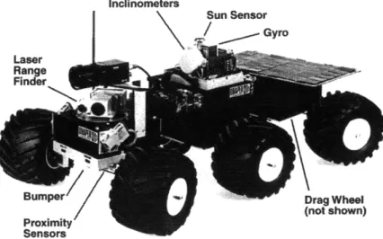
The most feasible design for the task of UXO detection and retrieval is a small, land-based, roving vehicle, or a micro-rover. Although aerial vehicles have a greater mobility, unobstructed by land obstacles, they also introduce the complex dynamics of flight and would have limited retrieval capability. Since a land-based vehicle can fulfill the task of UXO detection and retrieval, for most environments, it was decided to use the simpler micro-rover approach. Micro-rovers enjoy the benefits of being small, inexpensive, and relatively easy to control.
Inclinometers
S u n S e n s o r Gyro Laser
Range
Bum.pe Drag Wheel
(not shown)
Proximity
Sensors
Figure 1: MITy-2 Micro-rover 1.4 Intelligent Unmanned Vehicle Center
The Intelligent Unmanned Vehicle Center (IUVC) was first established in August 1990, as the Planetary Rover Baseline Experiment (PROBE) Laboratory. The laboratory represents a cooperation with the Charles Stark Draper Laboratory and area universities (MIT, Tufts, Boston University, and Northeastern University) to
actively foster research and design of intelligent systems including small robotic technologies. Currently eight graduate students and four undergraduate students from MIT comprise the staff in the center.
Since the inception of the PROBE Laboratory, the center has developed a solid background in autonomous robotics and intelligent systems. The IUVC boasts, as its core competencies, the following specialty areas:
* Smart Sensor Technology * Sensor Fusion
* Tele-operated Robotics * Autonomous Micro-rovers * Autonomous Helicopter
* Undersea Mobility - "tuna" concept
Early small vehicle designs include MITy-1 and MITy-2 (Figure 1) micro-rovers, which are functional proof-of-concept prototypes of autonomous robots. These robots present solutions to the problem of sensory-based perception by fusing the data from multiple sensors to provide information accurate enough for obstacle avoidance. These MITy prototypes are the predecessors for the current generation of land-based vehicles, which we have named the EOD series. EOD stands for
THE EOD ARCHITECTURE
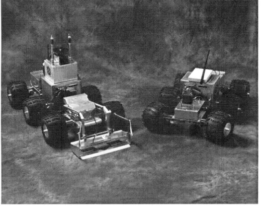
Figure 2: EOD-1 and EOD-2 Micro-rovers
Two rovers were built for the EOD project, EOD-1 and EOD-2. EOD-1 is a tele-operated system, which serves to show the mobility capabilities of the
mechanical platform as well as the option for tele-operated control. EOD-2 is a fully autonomous system that can complete an assigned task without operator assistance. 2.1 Mechanical Design
The EOD vehicles are equipped with a six-wheel drive flexible frame, front and rear Ackermann steering, a modular chassis, and a grappler device for UXO retrieval.
2.1.1 Flexible Frame and Modular Chassis
The vehicle's flexible frame provides a high degree of maneuverability, enabling the rover to traverse rocks, curbs and uneven terrain. The frame is
constructed of three individual platforms connected by spring steel wire. The front platform contains a metal detector unit, sonar, a contact switch bumper, and the 2-DOF grappler mechanism. Housed in the middle platform are the main processor, video camera and transmitter, wireless modem, local positioning transponder, and micro-mechanical rate gyro. Finally the rear platform contains the power regulation circuitry, the motor driver electronics, and the batteries.
2.1.2 Drive Train
The six wheel drive capability contributes to the exceptional maneuverability, producing speeds up to 1.8 m/s. Each aluminum wheel hub, fitted with a knobby
rubber tire, is powered by a small 12V DC motor with an integrated planetary gearhead and an optical, rotary encoder. The rotary encoders provide motor shaft rotation feedback for navigation purposes.
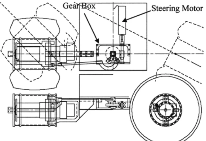
Figure 3: Schematic Diagram of Ackermann Steering Mechanism 2.1.3 Steering System
The Ackermann steering system intersects the axes of all the wheels at the center of the turning arc. This places each wheel tangent to the turning arc, reducing slippage and navigation errors. Powering the two Ackermann steering gear boxes are two 24V DC motors, also equipped with planetary gearheads and optical encoders.
The gearhead output shafts are coupled to doubly threaded worm gears, which are mounted in aluminum gearboxes near the front and rear of the micro-rover. (Figure 3)
The worm gears mate with worm wheels inside the gear boxes, providing an overall steering ratio of 30:1. The mechanical linkages combined with both front and rear "crab" steering yield a tight turning radius.
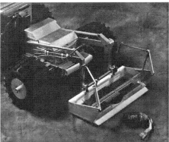
Figure 4: Grappler Mechanism 2.1.4 Grappler Mechanism
The grappler mechanism, shown in Figure 4, serves a dual purpose. It is used to both detect and acquire UXO in a Pick-Up-and-Carry-Away (PUCA) mission. The grappler mechanism has only been implemented on the EOD-2 rover. Embedded in the base of the acrylic grappler is a metal detecting unit used during the execution of a search pattern. Upon detecting the UXO, the grappler mechanism is used to scoop the UXO into the micro-rover for transport to the ordinance disposal area.
The grappler is driven by two 24V DC motors equipped with integrated gearheads and optical encoders. These encoders provide feedback of the position of the scoop and rake. One motor is used to actuate the scoop, while the other motor is used to drive the rake. The rake is used to sweep the UXO into the scoop during the acquisition process.
2.2 Main Processor Stack
The main processor stack is the central processing unit for the EOD micro-rovers. The main processing stack stores and executes the micro-rover's main program. The main processor stack has the following responsibilities:
* Collect data from the sensors * Process navigation and control * Command the actuators
* Communicate with the groundstation
The main processor stack is comprised of a Little Giant microcontroller and a PIO096 I/O expander.
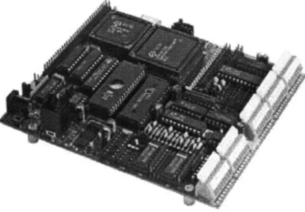
Figure 5: Little Giant Microcontroller 2.2.1 Little Giant Microcontroller
The main processor of the EOD micro-rover is located on the center platform of the EOD micro-rover. The main processor is a 12 MHz Little Giant
microcontroller based on the Zilog Z180 microprocessor. (Figure 5) The Little Giant includes:
* 512K of battery backed SRAM
* 16 digital I/O lines, 4 serial ports * an 8 channel A/D converter * a watchdog timer,
* and a 12 bit D/A converter.
The little giant is programmed with a proprietary variant on the C
programming language called Dynamic C. Programs are downloaded to the little giant through an RS-232 programming port. The program is stored on the non-volatile battery backed SRAM.
The Little Giant was chosen for its input/output capabilities and ability for rapid development. Programs can be written, compiled, run and debugged while the Little Giant is connected to a development PC. This allows monitoring the progress of the Little Giant during program execution. The Little Giant was also used in previous IUVC projects such as the MITy-2 (Figure 1) and the MITy-3. A keypad interface allows a keypad to be used to control the parameters and execution of the program stored in memory.
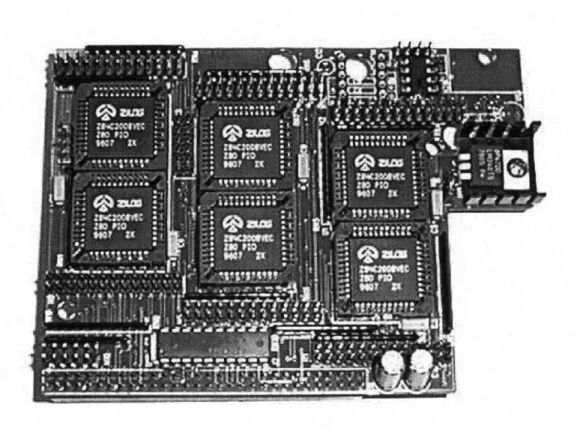
Figure 6: PIO096 Digital I/O Expander 2.2.2 PIO096 Digital I/O Expander
To accommodate the number of digital I/O lines required to interface to the sensors and actuators, it was necessary to add the PIO096 digital I/O expander board. (Figure 6) The PIO096, also made by Z-World engineering, adds 96 additional I/O lines to the functionality of the Little Giant Processor. The PIO096 is one of several add-on boards available for the Little Giant that can stack directly on top of the Little Giant microcontroller.
2.3 Sensors and Actuators
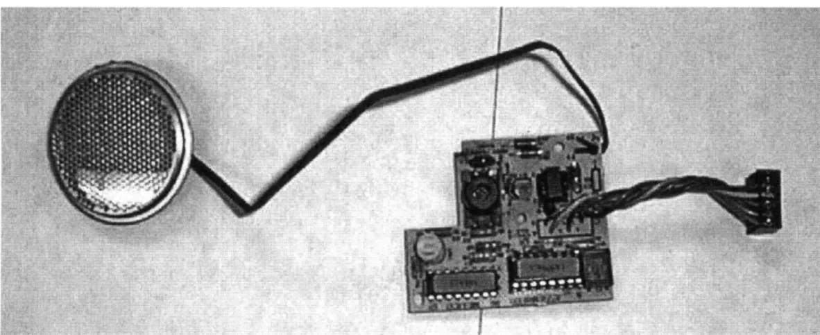
Figure 7: Polaroid Sonar Ranging Module 2.3.1 Sonar Ranging Module
The sonar rangefminder consists of three sonar transducers located on the front platform, one facing directly forward, the others facing slightly off to the sides. The sonar rangefinder is based on the Polaroid sonar ranging modules used on Polaroid instamatic cameras. The rangefinder works by emitting a sound pulse, which bounces off objects in the form of an echo. The amount of time it takes for the sound to make this round trip is proportional to the distance to the detected object. The Polaroid sonar ranging module, shown in Figure 7, consists of a circuit board and a transducer. The transducer is a thin circular disc contacted by two electrodes. One electrode contacts in the middle and the second contacts along the outer edge of the disc. The transducer is able to emit as well as detect sound pulses. The circuit board generates the 300V signal required by the transducer to produce a sound pulse, and detects the small voltage pulse produced when the echo returns to the transducer.
The transmission of the sonar pulse will trigger the echo detection circuitry if the detection circuitry is not disabled during transmission. Thus, controls for the echo detection inhibit (BINH) are also made available. Operation of the sonar ranging module is shown in Figure 8:
I I I I I II VDD t i I tlNIT-H ' NIT L I StECHO I BINH V I I I I I ECHO ,BINH I I I I
Figure 8: Polaroid Sonar Ranging Module Timing Diagram 16
* Upon applying +5v Vdd, the ranging module requires 5ms to stabilize (tpu). * INIT is brought high to emit the sound pulse.
* Delay 1.5ms to prevent false echoes from triggering receive circuitry (tBINH) * Bring BINH high to begin listening for echoes
* When an echo returns, ECHO is set high by the ranging module.
* The time between INIT going high and ECHO going high is proportional to the distance to the detected object.
The ECHO signal is an open collector output, so a pull-up resistor is necessary for proper operation. Generation of the 300v pulse causes spikes on the power supply lines. Placing a 500 tF capacitor at the power supply inputs of the ranging module can reduce the interference with other devices. A minimum delay of 200ms is
recommended between readings to allow the transducer to clear.
The sonar module implemented on EOD-2 was designed and built by Jong Kim. The control of the sonar ranging modules is handled locally by two Basic Stamps. The Basic Stamp is a PIC microcontroller that is programmed to work as a BASIC interpreter. The use of a local microcontroller to control the sonar ranging module frees the main processor to perform other tasks while waiting for an echo. Instead, the main processor simply sends a request to the sonar rangefinder module to perform a measurement. One Basic Stamp is used to initiate the firing of the three sonar ranging boards and the second Basic Stamp is used to measures the time until the echoes are received. After computing the distance to the nearest object from
+5v
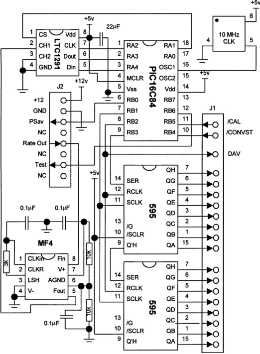
Figure 9: EOD-2 Gyro Module Circuit Diagram 2.3.2 Gyro Integration Module
The gyro integration module tracks the relative heading of the micro-rover by integrating the output of a micro-mechanical rate gyro. The gyro module first low-pass filters the rate output of the gyro to anti-alias the signal. The low-low-pass filter also serves to filter out high frequency noise signals that can be produced by switching power supplies and other noisy components. After being anti-aliased, the analog rate output is digitized with a 12-bit A/D converter. This result is then shifted, scaled and integrated by the embedded microcontroller to determine the relative angular
displacement. I designed and built the hardware for the Gyro module. Pehr Anderson coded the firmware aboard the gyro module's embedded processor. The circuit diagram for the gyro module is shown in Figure 9.
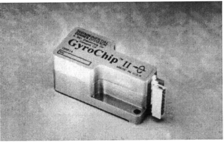
Figure 10: GyroChip-II Micro-mechanical Gyro 2.3.2.1 Micro-mechanical rate gyro
The sensor used on the gyro integration module is the GyroChip-II from Systron Donner (Figure 10). The GyroChip-II is a monolithic quartz sensor that measures an angular rotation rate. Angular rotation is measured using a vibrating quartz tuning fork. When the tuning fork is rotated on its longitudinal axis, the Coriolis effect is used to create a DC voltage proportional to the rate of rotation. This DC voltage is then amplified and presented as the gyro rate output. The output voltage is biased at +2.5 VDC and has a scale factor of 15 mV/o/sec with a range of 1000/sec. This yields an output voltage that ranges from +1 to +4 VDC. The GyroChip-II also has a TEST feature that simulates a 25°/sec rotation used for calibration, and a POWER SAVE feature to shutdown the gyro when not being used. 2.3.2.2 Anti-aliasing filter
To prevent harmonics from appearing on the digitized gyro rate output, it is necessary to sample at a minimum of two times the highest frequency of the input signal. Better results can be obtained by sampling at five to ten times the highest input frequency. To guarantee that the frequency of the highest frequency component of the input signal is known, it is common to low-pass filter or anti-alias the input signal. This low pass filter attenuates the amplitude of all signal components with a frequency above the filter cut-off. For the micro-rover, a cut-off of 50 Hz was chosen which is sufficient to capture the angular rates attainable by driving the micro-rover, while attenuating high frequency noise from the switching power supplies and nearby digital circuitry.
The anti-aliasing filter was implemented with a National Semiconductor MF4 chip which is a fourth order, switched capacitor, butterworth low pass filter. The MF4 was chosen because of its steep attenuation of signals above the cutoff
frequency and its ease of setting the cutoff frequency based on an external clock. The cutoff frequency of the MF4 is 1/100th of the frequency of the external clock. A 5
kHz clock is used to set the cutoff frequency at 50 Hz. 2.3.2.3 A/D converter and embedded microcontroller
The embedded microcontroller used for the gyro module is the PIC16C84. The PIC16C84 is a low-cost, small, 8-bit microcontroller. The PIC16C84 has 13 CMOS compatible I/O pins, a programmable 8-bit timer, a watchdog timer, and 1 K of program memory. The PIC16C84's program memory is stored in EEPROM, which allows reprogramming the microcontroller without having to UV erase the previous program.
A Linear Technologies LTC1291, two-channel, 12-bit A/D converter was used to digitize the anti-aliased, gyro rate out signal. The LTC1291 contains a serial I/O, successive approximation A/D converter. The LTC1291 has a built-in sample-and-hold and can be operated with a single power supply. The LTC1291 takes 12[ts to complete a conversion and the conversion results are shifted out of the converter with a four wire serial interface.
2.3.2.4 Software
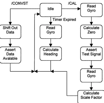
The software programmed into the EEPROM program memory of the PIC16C84 controls the A/D converter interface, the gyro TEST and POWER SAVE pins, and the main processor interface. The program uses an on-board timer to perform interrupt driven A/D conversions with a regular time base between each conversion. These conversions are then shifted such that the biased voltage of 2.5 VDC corresponds to zero drift, summed together to perform the integration, then divided by a constant scale factor to convert the integration result into degrees. To find the constant scale factor, the TEST pin on the gyro is asserted causing the gyro to simulate a 250/sec rotation. The corresponding digitized result can then be used to generate a scale factor conversion between the digitized rate output, and
degrees/second. A subroutine for calibration of the gyro can be initiated by the main processor by asserting the /CAL line.
Figure 11: Gyro Module Software Flow Diagram
The main processor makes a request for data by asserting the /CONVST line. The PIC16C84 then shifts the 16-bit heading data out onto two 8-bit serial-to-parallel shift registers. When the PIC 16C84 has completed shifting the data out to the shift registers, the PIC16C84 asserts the DAV line. The main processor can then read the heading from the 16-bit parallel data port. The data will remain on the port until another /CONVST is requested. The software flow diagram is shown in Figure 11. 2.3.3 Bumpers, Motor Limit Stops and Photo-detector Diodes
The bumper is located on the front platform, and is used to detect when the micro-rover has collided with an obstacle. The grappler motor limit stops are used to detect when the 2 DOF grappler mechanism has traveled to the extent of its possible motion. Without the limit stops, the main processor would have no way to know the absolute position of the grappler arm. Without knowing the grappler's position, the main processor would stall the motors whenever the main processor tried to drive the motors beyond their physical limits. Sustained stall conditions on the motors will eventually damage the motors. One motor limit stop is used to detect when the grappler has been positioned in its fully retracted position, and the other limit stop is used to detect when the scoop arm has been positioned its fully retracted position.
The bumpers and limit stops are mechanical switches that connect a resistor-tied-high output to ground. When the switches are in their normally open state, their outputs are pulled high with the pull-up resistors. When the switches is closed, their outputs are pulled to ground through the switches.
The two photo-detector sensors are fixed to the micro-rover, one near each steering mechanism. The photo-detectors are used as an absolute position reference for the steering angle. Each photo-detector sensor is a light emitting diode/photo-detecting diode pair. The diodes of the diode pair are positioned facing each other with a small gap between them. Light from the light emitting diode is sensed by the photo-detecting diode when there is nothing obstructing the gap between the two diodes. The photo-detecting diode acts much like the mechanical switch from the motor limit stops. When the photo-detector diode does not detect light, the output
line is pulled up with a pull-up resistor. When the photo-detector diode detects light, the output is pulled low with a transistor switch.
Attached to each steering mechanism is a thin sheet of metal that moves with the steering mechanism. As the steering mechanism moves, the sheet of metal is aligned to pass between the photo-detector diode pairs. The sheet is positioned such that the edge of the sheet passes between the diode pairs when the steering
mechanism is pointing directly forward. Thus the main processor can sense when the steering mechanism has been centered, as well as which direction to turn, to center the steering mechanism.
2.3.4 Encoders
The EOD micro-rover uses rotary encoders to measure the relative angular rotation of its motor shafts. Each of the six drive motors, two steering motors, and two grappler motors have a rotary encoder attached directly to the motor shaft. The rotary encoders allow the main processor to track how far the micro-rover has driven, how far the steering mechanism has turned, and how much the grappler has moved. Because the encoders only track relative motion, it is necessary to use the limit sensors and photo-detector diodes to sense the absolute position of the steering and grappler motors. Slotted Disk
Moto
Shafoto Little Giant Shaf -Main ... 118...119... Processor LE > Relative Quadrature AngularPhoto- Square Wave Position
detector
Figure 12: Encoder/Decoder Schematic
The encoder subsystem consists of two parts, the rotary encoder that encodes information about the angular rotation of the motor shaft, and the decoder that decodes rotary encoder's output and tracks the relative position of the motor shaft (Figure 12). The rotary encoder consists of a slotted disk and two LED/photo-detector diode pairs. The slotted disk is attached to the motor shaft while the diode pair is connected to the motor housing. Rotation of the motor shaft turns the slotted disk through the gap between the LED and the photo-detector diode. The alternating slots and solid portions on the slotted disk cause the photo-detector to generate a
square wave as the motor shaft is turned. The second LED/photo-detector diode pair is positioned such that the output is exactly 900 out of phase of the first LED/photo-detector pair. These quadrature square waves contain all the information necessary to determine the velocity and direction of rotation of the motor shaft.
The second component of the encoder subsystem is the decoder that decodes the quadrature output of the rotary encoders. The decoders are Hewlett-Packard's HCTL 2016 quadrature decoders. These decoders have a built in 16-bit counter that increments or decrements as the motor shaft turns.
CH A 1 +1 Reverse Forward 11 to (A) (B)
Figure 13: Quadrature Square Wave
Figure 13A shows a quadrature waveform. The waveform can be decoded using a finite state machine with the state transition diagram shown in Figure 13B. The first number in the state encoding represents channel A and the second number represents channel B. Thus the state '10' corresponds to when channel A is high and channel B is low. In Figure 13A, to represents state '00'. If the wheel is turned in the forward direction, channel A goes high and the finite state machine changes to state '10'. The output for this transition is '+1' so the counter tracking the motor shaft movement is incremented by one.
One limitation with this implementation is that the HCTL2016 uses a 16 bit counter to track the motor shaft position. If the counter counts past 65,535 or counts past 0 in reverse, the counter will roll over. The encoder has a resolution of 512 counts per revolution. With a tire circumference of 0.5 meters, the counter can track
approximately 60 meters before the counter rolls over. Since the micro-rover
routinely travels distances greater than 60 meters, the main processor must be able to detect and compensate for when the counter rolls over. The main processor
accomplishes this task by dedicating one variable to the distance traveled (DIST) and another variable to store the value of the last counter reading (LAST). The main processor then subtracts LAST from the current counter value to get the change in the counter value since the last reading (DELTA). If the DELTA is less than -32,768, that means that the counter has rolled over in the positive direction and 65536 must be added to DELTA to get the correct value. For example if the last value returned was 65530, and the current value reads 15, the difference is -65,521. After adding 65,536, the correct value of 21 is obtained. If DELTA is greater than 32,768, then the counter has rolled over in the negative direction and 65,536 must be subtracted to obtain the correct value.
If the counter is allowed to change by a value greater than 32,768 between reads, then the main processor will be fooled into believing that the counter has rolled over, or has rolled over in the wrong direction. A counter change of 32,768
corresponds to a distance of approximately 30 meters. Travelling at the maximum speed of 1.6 meters/second, the micro-rover can travel 30 meters in 18.75 seconds. Thus the main processor must read at least once every 18.75 seconds to correctly track the distance traveled. The encoders are also used to measure the average velocity of the micro-rover. Average velocity is determined by dividing DELTA by the time between counter reads. This measured average velocity is used as feedback in the motor velocity control loop.
)
motor 2016 SEL encoder motor 2016 encoder HCTL 2016motor Encoder Board
encoder
Figure 14: Encoder Board Block Diagram
The EOD-2 micro-rover has ten motors with one encoder for each motor. The quadrature square wave outputs of all of the encoders are fed to the encoder board on the center platform. The encoder board has ten HCTL2016 decoders, one for each encoder. The 8-bit outputs of each decoder are shared on an 8-bit bus going directly to the main procesor as shown in Figure 14. The HCTL2016 has built-in tri-state outputs, which allow bus interfacing without glue logic. The main processor selects which decoder to read using two 3-to-8 demultiplexors cascaded together to form a 4-to-16 demultiplexor. A demultiplexor was used to assure that only one decoder could be active at any time to prevent bus contention. The reset control line (not shown) is shared amongst all the decoders allowing a master reset that allows all the counters to be zeroed. The high/low byte control line (not shown) is also shared amongst all the encoders, but is ignored if the decoder is not selected.
LMD18245
SMotor Drivers
Serial-to-Parallel Shift Register
Figure 15: Motor Driver Module 2.3.5 Motor Driver
The motor driver subsystem takes torque commands from the main processor and applies the necessary current to the motors to generate the commanded torque. The EOD micro-rover has ten motors consisting of six drive motors, two steering motors, and two grappler motors. Each motor driver is controlled by a four-bit torque command, a direction bit, and a brake bit. Thus the motor can be commanded to 31 unique torque levels, 15 forward, 15 reverse and stopped. The brake control shunts the motor terminals together and forces any currents generated by motion of the motor to re-circulate and decay to zero.
The motor-driver modules are built on printed circuit boards with two motor drivers on each board (Figure 15). The motor driver is built around the National Semiconductors LMD18245 motion controller chip. The LMD18245 is a 3A, 55V DMOS full-bridge motor drover. The major components of the LMD18245 are a 4-bit DAC, a voltage comparator, a monostable timer, a DMOS full H-bridge, and a
current sense amplifier.
The LMD 18245 regulates the torque using a fixed off-time chopper amplifier. The 4-bit torque command is first converted to an analog voltage by the 4-bit DAC.
The comparator compares the commanded torque to the output of the current sense amplifier. The current sense amplifier sources 250 pA per ampere of current in the motor. Thus by placing a current sense resistor between the current sense amplifier and ground, a voltage is established that is proportional to the current in the motor. Changing the current sense resistor changes the sensitivity range for the motor
current. As long as the current through the motor is less than the commanded current, the monostable will remain on and the motor current will ramp up. Once the motor
Motor+ Direction Control Logic Brak Current Sense Amplifier Comparator RC Monostable 4-Bit DAC CS UT 1 2 3
Figure 16: LMD18245 Functional Block Diagram
current exceeds the commanded current, the comparator will trip the monostable. The monostable will then shut off the H-bridge for a fixed amount of time. This fixed amount of time is specified by an external RC network. While the H-bridge is off the motor current will decay. When the monostable timer expires, the H-bridge will turn back on and begin to ramp up the current through the motor again. This switching on and off of the H-bridge based upon the output of the comparator forms the chopper amplifier.
Vcc Vcc Vcc
1 3 1 3 1 3
Motor Motor Motor
2 4 2 4 2 4
(A) (B) (C)
Figure 17: H-bridge Operation
The H-bridge consists of four power switches arranged such that the motor can be driven in both directions using only a single polarity power source. In Figure 17A, switches 1 and 4 are closed completing the circuit such that the positive terminal is on the left of the motor and ground is on the right. In Figure 17B, switches 2 and 3 are closed reversing the direction of current in the motor causing the motor to spin in the opposite direction. Figure 17C represents the brake mode, where switches 2 and 4 are closed causing the current to re-circulate through the motor and decay.
Motor-Sin Brake Dir 1
D Dir 2
Sout
Figure 18: Motor Driver Module Block Diagram
Each motor requires six bits of control: four torque bits, one direction bit and one brake bit. Ten motors would have required sixty I/O lines from the main
processor. To reduce the number of lines, the torque-input lines of each LMD 18245 have been buffered with a serial-to-parallel shift register. The shift registers are eight-bit shift registers, so one shift register can service two motor driver chips. The I/O lines required to control the serial-to-parallel shift registers are:
* the data line (DATA) where the bit to be shifted-in is presented, * the serial clock (SCK) to shift data through the shift registers,
* and the register clock (RCK) to latch the output registers with the data held by the shift registers.
The serial-to-parallel shift register reduces the original sixty lines required to twenty-three. Sharing the brake line for the drive motors further reduces the number of lines to eighteen; ten direction lines, five brake lines, DATA, RCK, and SCK.
2.4 Data Bus
2.4.1 Parallel Dedicated Data Lines
The wiring architecture uses dedicated data lines for each peripheral device. This architecture was chosen based on its success in the earlier MITy prototypes. This architecture allows the designer for each device to independently design the peripheral's interface to the main processor. The benefits of dedicated data lines include:
* A high bandwidth communication channel between the main processor stack and the peripheral devices
* The failure of a peripheral device will not interfere with communication between the main processor stack and other peripheral devices.
* Devices can be connected and disconnected without affecting other peripheral devices.
The disadvantages associated with this approach include: * High material and labor costs.
* Difficult documentation and debugging. * Large numbers of dedicated I/O lines 2.4.2 Wiring and Interconnects
Since the vehicle is broken into three platforms, the wiring is designed to be modular, allowing the platforms to be easily connected and disconnected. On each platform are a DB50 data connector and a DB50 power connector. The data
connector carries low current signals that connect the sensors to the microprocessor. The power connector carries the high current signals that drive the motors. The high current and low current wires were placed and routed separately to minimize crosstalk interference. Inside the center platform is a backplane through which all the wires to and from the processor pass. This design allows for easy replacement of the
processor should the processor fail. In the rear platform the motor driver modules are connected in series as shown in Figure 19.
Device Device
Device Device
SDevice kplDevice
Rear Middle Front
Platform Platform Platform
Figure 20: ProxLink Wireless Modem 2.5 Communications
Communication between the micro-rover and the groundstation is accomplished with a pair of ProxLink Wireless Modems made by Proxim. The ProxLink is a wireless replacement for a standard RS-232 serial cable. The ProxLink operates in the 902-928 MHz band, can span distances up to 300 meters, and can transfer data at speeds up to 19.2Kbps. The ProxLink uses spread spectrum technology to overcome interference and allow multiple ProxLinks to operate simultaneously.
2.6 Joystick Control Station
EOD-1 operates under tele-operated joystick control. The joystick control station consists of a standard PC joystick, a Z-World little giant processor, and a proxim modem. Forward and backward movement of the joystick controls the six drive motors. Left and right movement of the joystick operates the front and rear steering motors.
The standard PC joystick was designed to minimize the cost. In the early days of personal computers, analog-to-digital converters were large and expensive, while voltage comparators were relatively cheap. Thus the standard joystick interface used
Vcc Vcc r --- R R R Joystick I Vx
S---Figure 21: PC Joystick Schematic Diagram
Inside the standard joystick are two potentiometers connected to the handle (Figure 21), and two normally open push-buttons. The potentiometers are used as variable resistors such that the resistance seen by the computer varies as the handle is moved. Inside the computer are capacitors and two square wave generators. The capacitor connects in series with the potentiometers in the joystick to form a RC circuit. The computer then feeds the square wave through the RC circuit and compares the output to a fixed voltage set at 2.5V. Thus to measure the position of the joystick, the computer measures the amount of time between when a rising or falling edge occurs in the original square wave, and when the output voltage crosses the threshold voltage set around 2.5 volts. The greater the resistance in the joystick, the greater the RC time constant, causing a longer delay before the output voltage crosses the threshold voltage.
Since the little giant has built in analog-to-digital converters, it was more convenient to modify the output of the joystick to produce an analog voltage output instead of a varying resistance output. The voltage output was obtained by using the resistance output of the joystick to form the lower half of a voltage divider circuit. By matching the maximum resistance of the joystick to the resistance of an external resistor used as the upper half of the voltage divider, a 5V input voltage would output a voltage between OV and 2.5V based on the position of the joystick. One problem with using this method to generate an output voltage is that the output voltage does not vary in proportion to the position of the joystick. Compensation for the varying scale factor can be calculated using Equation 1. Rs is the external resistance equal to the maximum resistance of the internal joystick potentiometer. Vcc is tied to the positive voltage supply. Vj is the voltage output of the joystick as read by the analog to digital converter. Rj is the resistance value of the internal joystick potentiometer, which is directly proportional to the position of the joystick.
RV, Vcc - V,
Equation 1: Joystick Compensation
The buttons on the joystick are implemented similar to the bumpers on the micro-rover. The buttons are contact switches that are normally open. When the buttons are not depressed pull-up resisters pulls the button signal lines high. When a button is depressed, the button signal line corresponding to the button depressed is pulled low. Once the processor connected to the joystick calculates the position of the joystick and the state of the buttons, the processor packetizes the information into a format suitable for transmission to the micro-rover. The joystick processor then sends three-byte packets to the micro-rover via the proxim modem pair. Each byte of the packet is a combination of a two-bit header and a six-bit data field.
* A 01 in the header means that the data field describes the X position of the joystick.
* A 10 in the header means that the data field describes the Y position of the joystick.
* A 00 in the header describes which buttons on the joystick are depressed. * 11 is not used and any packets with 11 as the header are discarded.
The joystick interface code running onboard theEOD-1 then uses the headers to determine the contents of the data. Once the header is decoded, the header is stripped and the data is processed. The six bits in the Y-position correspond to the
commanded drive current, and can take values from 0 to 64. Since 32 corresponds to the joystick Y-position center, the joystick interface code subtracts 32 and divides the Y-position data by 2 to get values between -16 and 16. The sign of the commanded torque is used to set the direction bit of the LMD 18245 and the absolute value of the commanded torque is sent to the 4-bit torque input of the LMD 18245. This scheme allows EOD-1 to be driven in torque-control mode with a standard PC joystick. The code on EOD-1 used to interpret the joystick commands is listed in Appendix A.
ARCHITECTURE CHANGES
The construction, development and programming of the EOD micro-rovers led to many ideas for improvements to the EOD architecture. This chapter covers the problems discovered with the original EOD architecture and presents changes to
solve those issues. 3.1 Main Processor
During the programming phase of development, it became evident that the Little Giant was having difficulty processing all the low level driver code in addition to the high level behavioral code. Essentially, the Little Giant simply did not have enough resources to handle both tasks at the same time. Earlier micro-rovers using the same microprocessor did not have as many complex sensors and actuators as the EOD vehicles. Since the Little Giant implements the motor control loop, the Little Giant has to constantly monitor and update the status of the motors. This made even
simple tasks such as driving at a constant velocity a resource burden on the Little Giant. To relieve the burden the Little Giant, high level tasks were eventually moved to the groundstation, and the EOD micro-rover lost the ability to autonomously perform path planning and navigation without assistance from the groundstation.
Part of the solution to these problems is to upgrade the main processor. Changing to an Intel X86 based processor would, in one step, fix many of the limitations associated with the Little Giant. A 486 processor running at 50MHz would have much more computing power than the Little Giant, which would allow the path-planning and navigation code to reside on-board the micro-rover. Also, the use of a standard processor such as an X86 based processor would allow freedom of choice in the operating system. The micro-rover could run QNX for its real-time capabilities, or Linux, the OS used on the groundstation.
One problem with a X86 based processor is that the X86 processor is designed as a general-purpose computer. This is in contrast to the Little Giant, which is
designed as an embedded micro-controller. The Little Giant has many digital and analog I/O ports for directly controlling peripheral hardware. The X86 based processor has only 2 serial ports and a parallel printer port for built-in I/O. The X86 processor relies on its bus to communicate to expansion cards for additional I/O. To directly replace the Little Giant with an X86 based processor would also require multiple digital and analog I/O expansion cards. To avoid adding the need of
expansion cards, a different method for communication between the processor and the peripheral devices needs to be used. In other words the new method of
SENSOR CPU SENSOR ACTUATOR ACTUATOR CPU P SENSOR SENSOR (A) (B)
Figure 22: Bus Architecture
3.2 Smart sensors and actuators
One problem still unaddressed by the migration to a new processor, is the often resource intensive task of low-level hardware management. The original architecture design was a centralized processing architecture where almost all data processing occurred at the main processor. The sensors communicated raw data to the main processor for processing into meaningful data. Likewise the actuators received low-level hardware commands directly from the main processor (Figure 22A). Much of the hardware driver software is run on the main processor. Putting the main processor in the control loop greatly burdens the main processor. For example, the motion control driver code for the motor drivers has velocity for its input and has torque as its output. The driver code constantly compares the velocity of the motor as read from the motor encoder, to the commanded velocity. If the commanded velocity is greater than the motor velocity, the driver code increases the commanded torque. In order for the micro-rover to maintain a smooth velocity over uneven terrain, the velocity must be sampled with a fast rate. In the original architecture, the main processor must sample all six wheels, calculate the necessary torque, and command all six motors with the new torque command. All these steps must be completed at a rate fast enough maintain smooth motion. If more motors are to be driven at the same time, then the problem is compounded.
The solution to this is to distribute the processing; move the high bandwidth control loops to the peripheral device. This method requires a dedicated embedded processor to be located at each sensor and actuator (Figure 22B). In the case of the motor driver, the local processor's responsibilities include maintaining the motor's velocity at the commanded velocity. The locally embedded processor would use the
same method as described above, but now the main processor is freed from the processor intensive task of maintaining motor velocity. The main processor now needs only to command the desired velocity to the motor driver's embedded processor, and the motor driver's embedded processor would handle the rest.
Additional motor drivers would have very little impact on the main processor's use of resources.
Using a locally embedded processor to perform the low-level hardware control means the main processor no longer communicates directly with the
hardware. The main processor now communicates to the hardware through a layer of abstraction presented by the microcode aboard the embedded processor. Should the hardware implementation change, the embedded processor could emulate the same interface as the original hardware. This would prevent the need for any changes to the main processor software.
Another drawback to the original architecture is the required bandwidth. Since the motor drivers could only regulate torque, in order to maintain velocity, the torque had to be updated regularly. Let's assume that it is desired to update the motor drivers with a frequency of 15 Hz. During each update cycle, the encoder is read twice, once for the low byte and once for the high byte, and the torque is commanded once. With six drive motors that means data is sent to or from the processor at a rate of 270 times a second, just to travel at a constant velocity. Once an embedded
processor is used to maintain velocity, the main processor needs only to command the desired velocity once. The results are that the control loop is no longer in the bus traffic and the bus traffic is no longer sample rate dependent.
The final drawback to the original architecture is the wiring involved. Since each sensor and actuator in the original architecture has no bus interface logic, each sensor and actuator had its own dedicated lines to the main processor. This was shown to be a major inconvenience during the construction phase of the EOD micro-rovers. A team of students was dedicated, for over a week, to the task of crimping the approximately two thousand wire crimps necessary. There are several ways to reduce the number of wires involved:
* Serialize data transfers between the main processor and the peripheral device. Bandwidth studies must be performed to be sure that serial communication will have sufficient bandwidth to replace the parallel communication.
* Share the wires on a bus. Since the main processor only communicates to one peripheral device at a time, most of the wires are not being used at any given time.
This allows the wires to be shared in the form of a bus. Implementing the bus would necessitate tri-state buffers at each peripheral device and a device-addressing scheme.
The approach chosen for the new architecture incorporates both of these schemes. The local embedded processor communicates data serially over two wires, and these two wires are shared as a common bus for all peripheral devices. This would reduce the number of wires by a factor of ten, reducing the cost and time to manufacture.
3.3 I2C Data Bus
The use of locally embedded processors to manage the operation of peripheral devices, allowed reducing the bandwidth of data sent over the data bus. This
reduction of bandwidth allowed the selection of a low-bandwidth serial bus. High bandwidth control loops like velocity feedback control are all handled locally and off the serial bus.
3.3.1 Advantages and Disadvanteges
The Inter-Integrated Circuit serial bus, or I2C, is a simple, low-cost, easy to implement master-slave protocol. I2C has many benefits for both the designer and the manufacturer.
* I2C is a standardized bus interface, which is already integrated into the hardware of many IC's.
* 12C allows independent design of the peripheral device hardware and allows the data-transfer protocol to be completely software controlled.
* Devices can be connected or disconnected from the bus while the system is operating without affecting other devices on the bus.
* Design, testing and debugging of a peripheral device can be performed on a standard test setup, off-board the vehicle.
* The number of devices that can be added are limited only by the device address specification, or by the bandwidth of the bus.
* I2C reduces the wiring to a two-wire serial bus that is simple to manufacture and is less costly in terms of wires and connectors.
* I2C eliminates the need for address decoding "glue-logic"
The disadvantages associated with selecting I2C for the bus protocol are: * Low bandwidth - less than 100Kbps in normal mode or 400Kbps in fast mode * I2C forces the peripheral designer to conform to the I2C interface.
* A stuck-low failure on any peripheral device will tie up the bus and bring the entire system down.
3.3.2 Specification
I2C is a two wire, master-slave, wired-AND, serial bus. One wire is used for data (SDA) and the other wire is used for the clock (SCL). 12C is a master-slave protocol; one device acts as the master and controls all communications, while another device acts as a slave. The master generates the clock, and the slave must acknowledge all communications. I2C has support for multiple masters and can handle arbitration and network collisions.
3.3.2.1 Hardware
The 12C bus is a wired-AND design with each line pulled high by a pull-up
resistor. Devices transmit a low by actively pulling the line low and set the line high by freeing the bus and allowing the pull-up resistor to pull the line high. Thus
devices on the bus must have an open collector, or an open drain connection to the bus. Normal CMOS outputs cannot be used to drive the bus lines.
I2C has two speed protocols, the standard-mode I2C supports data transfers at speeds up to 100Kbits/sec and the high speed-mode allows data transfers at speeds up to 400Kbits/sec. The limiting factor on designing an I2C bus is the bus capacitance.
Since the lines are passive-high, capacitance on the bus limits the rise time and thus the bandwidth. To decrease the rise time, smaller pull-up resistors can be used, but then the bus current consumption increases. Tables to size the pull-up resistors based on the bus capacitance are given in the I2C specification published by Philips
Semiconductors'. In general the I2C bus can support busses with capacitances up to 300 pF
3.3.2.2 Bit transfer specification
One clock pulse is used for each bit transferred. For data bits, the data line (SDA) is not allowed to change while the clock line (SCL) is high. All transitions for the data line must occur while the clock line is low (Figure 23).
SDA
SCL
Data Allowed Data Must
To Change Remain Stable
Figure 23: Data Bit Transfer Diagram
I---SDA l I lI
I I I I
SCL ,'
Start Bit hg R Stop Bit
Figure 24: Start Bit and Stop Bit Transfer Diagram
The two exceptions to this rule are the start bit and the stop bit (Figure 24). The start bit is used to signify the start of a data transmission and the stop bit is used to signify the end of a data transmission. Setting the data line (SDA) from high to low while the clock line (SCL) is high, signals a start condition. Likewise, changing the
data line from low to high while the clock line is high signifies a stop bit. Devices that do not have on-chip 12C interfaces must poll the data line for the start and stop bits.
3.3.2.3 Byte transfer specification
Transmitter SDA
Receiver SDA
SCL
Acknowledge Bit ,
Figure 25: Acknowledge Bit Transfer Diagram
Data on the 12C bus is formatted into 8-bit bytes sent MSB first. The receiver
must acknowledge each byte sent by the transmitter (Figure 25). During a byte transmission, the transmitter leaves SDA high during the ninth clock cycle of the byte. During this ninth clock cycle, the receiver must pull SDA low to acknowledge the byte. If the receiver needs time to process the byte before receiving the next byte, the receiver can delay the transmission of the next byte by holding SCL low after the acknowledge bit. The transmitter must go into a wait state if it detects that SCL is held low by the receiver, after the acknowledge bit, and continue with the next byte as soon as it detects the SCL line being released.
3.3.2.4 Device addressing
The first byte sent by the master is constructed from the 7-bit address of the slave device, and an eighth bit that specifies the data transfer direction. If the LSB of the address byte is low, the master device will write data to the slave device. This mode is called master-transmitter or slave-receiver. If the LSB is high, then the master device will read information from the slave device. This mode is called master-receiver or slave-transmitter. In both cases, the master device generates the SCL.
When a start bit is sent, all devices on the bus compare their address to the address sent in the following byte. If the addresses match, the corresponding slave device will acknowledge the byte during the ninth clock cycle. If no slaves match the address byte, or the corresponding slave device is busy and is unable to receive, the master must issue a stop condition, and retry the transmission. If the address byte is acknowledged, communication will then proceed between the master and the slave until a stop condition is issued.
3.3.2.5 Data transfer specification
Start RNV Ack Stop
Bit WABit / Bit Bit
(A) S Addressbyte
WI
A DataByte A DataByte A P(B) S Address byte W A Data Byte A Data Byte A
I
(C) S Address byte W A Data Byte
Al
S Address byte R ...Data Byte A Data Byte A IPI
Figure 26: Data Transfer Modes
There are three modes of communication supported by 12C, master write to slave, master read from slave, and a hybrid master read/write from slave.
* Master write to slave (Figure 26A)
The master starts the transmission with a start bit. Then the master transmits the slave address with the R/W bit low to specify a write transfer. The slave device acknowledges the address byte. The master then transmits data bytes allowing the slave device to acknowledge each byte. After the last byte is acknowledged, the master terminates the data transfer with a stop bit. * Master read from slave (Figure 26B)
The master starts the transmission with a start bit. Then the master transmits the slave address with the R/W bit high to specify a read transfer. The slave device acknowledges the address byte. The master then clocks the data in from the slave device, with the master acknowledging each byte. After the last byte is received, the master notifies the slave to free the bus, by not acknowledging the last byte. The master then terminates the data transfer with a stop bit.
* Hybrid transfer (Figure 26C)
The hybrid transfer is used when information needs to be sent to a slave device before data can be read from the slave device. An example is an I2C EEPROM, the address to be read is first written to the EEPROM, then the data at that address is returned to the master.
The master starts the transmission with a start bit. Then the master transmits the slave address with the R/W bit low to specify a write transfer. The slave device acknowledges the address byte. The master then resends a start bit and an address bit, this time with the R/W bit high specifying a read transfer. The master then clocks the data in from the slave device, acknowledging each byte. After the last byte is received, the master notifies the slave to free the bus, by not
acknowledging the last byte. The master then terminates the data transfer with a stop bit.
3.4 Communications
The original communications protocol used RF modems that passed communications between the micro-rover serial port and the ground station serial port. This form of serial communication is primarily a point-to-point protocol and usually limited to two devices. Although possible, multiple micro-rover exercises using the RS-232 protocol would be difficult and complex. Currently the two EOD
micro-rovers can work simultaneously by using two different RF modem frequencies. A different approach to micro-rover communication is to use wireless
Ethernet. Ethernet would be an ideal medium for communications because it would allow many rovers to operate simultaneously. Each micro-rover would be equipped with the same Ethernet hardware, but have a unique IP addresses. Essentially each micro-rover would be a client in a local area wireless network and the ground station would be the server. An additional benefit of Ethernet is guaranteed packet delivery. 3.5 Software
The Intel x86 processor is supported by many operating systems. Two notable operating systems are Linux and QNX. All the on-board micro-rover
software was developed using a software simulation of the hardware in the Linux OS. Using Linux on the micro-rover would minimize the effort required to port the code from the simulator to the actual micro-rover. QNX, on the other hand, has a real time kernel that is preferred for devices that must interact with real world stimuli.
Selecting the optimum operating system to use is a decision that requires further research.
THE PROPOSED ARCHITECTURE
4.1 Main processor stack
Figure 27: Ampro CoreModule/486-II 4.1.1 Ampro CoreModule/486-II microprocessor
The CoreModule/486-II (Figure 27) is a small modular processor that incorporates the major components of a 486SLC PC/AT compatible desktop computer. The components include:
* Low-power CX486SLC2-50 CPU * 1Kbyte internal cache
* 16Mb DRAM * Real-time clock
* Standard DMA support * Bi-directional parallel port * Two RS-232C serial ports * Keyboard interface
* Speaker interface
* Solid state disk capability * Watchdog timer