• Aucun résultat trouvé

Achieving resonance in the Advanced LIGO gravitational-wave interferometer

N/A
N/A
Protected

Academic year: 2021

Partager "Achieving resonance in the Advanced LIGO gravitational-wave interferometer"

Copied!
18
0
0

Texte intégral

(1)

Achieving resonance in the Advanced

LIGO gravitational-wave interferometer

The MIT Faculty has made this article openly available.

Please share

how this access benefits you. Your story matters.

Citation

Staley, A. et al. “Achieving Resonance in the Advanced LIGO

Gravitational-Wave Interferometer.” Classical and Quantum Gravity

31, 24 (November 2014): 245010 © IOP Publishing Ltd

As Published

http://dx.doi.org/10.1088/0264-9381/31/24/245010

Publisher

IOP Publishing

Version

Original manuscript

Citable link

https://hdl.handle.net/1721.1/121229

Terms of Use

Creative Commons Attribution-Noncommercial-Share Alike

Detailed Terms

http://creativecommons.org/licenses/by-nc-sa/4.0/

(2)

LIGO-P1400105 1

Achieving Resonance in the Advanced LIGO

Gravitational-Wave Interferometer

A. Staley1, D. Martynov5, R. Abbott5, R.X. Adhikari5, K. Arai5, S. Ballmer6,

L. Barsotti9, A.F. Brooks5, R.T. DeRosa3, S. Dwyer2, A. Effler3, M. Evans9,

P. Fritschel9, V.V. Frolov4, C. Gray2, C.J. Guido4, R. Gustafson8, M. Heintze4,

D. Hoak10, K. Izumi2, K. Kawabe2, E.J. King12, J.S. Kissel2, K. Kokeyama3,

M. Landry2, D.E. McClelland7, J. Miller9, A. Mullavey3, B. O’Reilly4,

J.G. Rollins5, J.R. Sanders8, R.M.S. Schofield11, D. Sigg2, B.J.J. Slagmolen7, N.D. Smith-Lefebvre5, G. Vajente5, R.L. Ward7, and C. Wipf9

1Department of Physics, Columbia University, New York, NY 10027, USA 2LIGO Hanford Observatory, PO Box 159, Richland, WA 99352, USA

3Louisiana State University, Baton Rouge, LA 70803, USA 4LIGO Livingston Observatory, Livingston, LA 70754, USA 5LIGO, California Institute of Technology, Pasadena, CA 91125, USA 6Department of Physics, Syracuse University, Syracuse, NY 13244, USA

7Australian National University, Canberra, ACT 0200, Australia 8University of Michigan, Ann Arbor, MI 48109, USA

9LIGO, Massachusetts Institute of Technology, Cambridge, MA 02139, USA 10University of Massachusetts Amherst, Amherst, MA 01003, USA

11University of Oregon, Eugene, OR 97403, USA 12University of Adelaide, Adelaide, SA 5005, Australia

Version 5, September 9th, 2014

Abstract

Interferometric gravitational-wave detectors are complex instruments comprised of a Michelson interferometer enhanced by multiple coupled cavities. Active feedback con-trol is required to operate these instruments and keep the cavities locked on resonance. The optical response is highly non-linear until a good operating point is reached. The linear operating range is between 0.01% and 1% of a fringe for each degree of freedom. The resonance lock has to be achieved in all five degrees of freedom simultaneously, making the acquisition difficult. Furthermore, the cavity linewidth seen by the laser is only ∼ 1 Hz which is four orders of magnitude smaller than the linewdith of the free running laser. The arm length stabilization system is a new technique used for arm cavity locking in Advanced LIGO. Together with a modulation technique utilizing third harmonics to lock the central Michelson interferometer, the Advanced LIGO de-tector has been successfully locked and brought to an operating point where detecting gravitational-waves becomes feasible.

(3)

PRM SRM ITMX ETMX ITMY ETMY BS LASER End Station Laser End Station Laser Anti-symmetric Port Carrier 1064 nm 45 MHz RF Sideband 9 MHz RF Sideband 532 nm Beam Infrared Reflection Signal Pick Off Port Infrared Transmitted Signal Infrared Transmitted Signal Gravitational wave Readout Lx lx lp ls Ly ly PRM SRM ITMX ETMX ITMY ETMY BS LASER Ly Lx lx lp ly ls

Figure 1: Simplified optical layout of the Advanced LIGO detector. A beamsplitter (BS) is used to separate the light into an X-arm and a Y-arm. Each arm is comprised of an input test mass (ITM) and an end test mass (ETM) forming the arm cavity. The Michelson interferometer is operated near a dark fringe which reflects most of the injected laser power back towards the laser. The partially transmitting power recycling mirror (PRM) is used to enhance the circulating power until most of the power is lost internally. The signal recycling mirror (SRM) is used to enhance the optical response to a gravitational-wave. The common mode is defined by (Lx+ Ly)/2, the differential mode by Lx− Ly, the power recycling length by lp+ (lx+ ly)/2, the signal recycling length by ls+ (lx+ ly)/2, and the Michelson length by lx− ly. The macroscopic part of the Michelson length is called the Schnupp asymmetry. The interferometer detector ports are highlighted in the diagram. This includes the reflection port, pick-off port, and anti-symmetric port. The infrared transmitted signals are required for full locking (see Section 4). The various frequency components of the light used to control the five degrees of freedom of the interferometer are also depicted. The 9 MHz and 45 MHz RF sidebands are used to track the length of the power and signal recycling cavities, respectively. The 532 nm beam is used to independently control the two arm cavities. The 1064 nm carrier resonates in all cavities but the signal recycling one. The inset shows the fundamental noise limits of the Advanced LIGO design as an amplitude spectral density.

(4)

1

Introduction

A new generation of advanced gravitational-wave detectors is currently under construc-tion, including Advanced LIGO[1], Advanced VIRGO[2], and KAGRA[3]. Their goal is to establish the first direct detection of gravitational waves on Earth[4] and to start the regular observation of astrophysical sources[5–10]. The aim of their design is to measure gravitational waves with a strain as small as 4 × 10⁻²⁴/√Hz. All advanced detectors employ kilometer-scale Michelson interferometers which have their best sensitivity in the 100 Hz region. The corresponding requirement for length resolution is then ∼ 10−19m rms within a 100 Hz bandwidth[1]. This high sensitivity requires multiple optical cavities to enhance the response of the Michelson interferometer (see Fig. 1). First, Fabry-Perot cav-ities are added to each Michelson arm to effectively increase the arm length by two orders of magnitude. Secondly, partially transparent mirrors are added to the symmetric and the anti-symmetric ports of the Michelson interferometer to recycle the laser power and extract the gravitational wave signal, respectively[11, 12]. These extra optical resonators are called power recycling cavity and signal recycling cavity. They further enhance the detected sig-nal, but add the complication of keeping two more cavities on resonance. Additionally, the Michelson interferometer must be held at the point of minimum output power (dark fringe condition). In doing so, most of the light returning from the arm cavities is directed back to the main laser and recycled to the interferometer, increasing the overall sensitivity.

Cavities can be locked to a resonance using the Pound-Drever-Hall (PDH) reflection locking technique[13]. This requires adding phase-modulated radio frequency (RF) side-bands to the input light and detecting the reflected light using a demodulation scheme[14]. A variant of this technique exploits the Schnupp asymmetry [15] to keep the Michelson operating on a dark fringe. For Advanced LIGO the three main detection ports are in reflection of the full interferometer, at the anti-symmetric port, and in reflection of the beamsplitter using a small pick-off beam. With high finesse cavities the Pound-Drever-Hall technique has a very small linear operating point. Outside this region the error signal is either negligible or misleading. Furthermore, if the laser frequency sweeps over a reso-nance faster than the cavity storage time, the light inside the cavity does not have enough time to fully build up. The resulting Pound-Drever-Hall signal can display multiple Doppler peaks, further confusing any controls scheme[16–18].

The goal of the initial controls of an advanced detector is to bring all five degrees of freedom to the linear operating point. These five degrees of freedom consist of the common mode, differential mode, Michelson length, power recycling length, and the signal recycling length as described in Fig. 1. Because of the two recycling cavities all degrees of freedom are strongly coupled. The state of the recycling cavities has a large effect on the signals from the arm cavities, whereas the state of the arm cavities can completely alter the signals seen by the dual-recycled Michelson interferometer. In the initially built configuration of LIGO[19, 20] no signal recycling cavity was used[21, 22]. The locking scheme first locked the power-recycled Michelson interferometer before using a stochastic approach to catch each arm cavity[23]. This was neither predictable nor robust, and typically required multiple locking attempts. VIRGO used another approach whereby the arm cavities were locked first, followed by the power-recycled Michelson interferometer. This locking scheme transmitted most of the light into the anti-symmetric port to broaden the cavity linewidth of the power-recycled Michelson interferometer[24]. However, it is unclear how this technique can be extended to include a signal recycling cavity. For Advanced LIGO a new arm

(5)

length stabilization system was devised to make locking reliable and repeatable, while being compatible with the new optical configuration.

Id Description Wavelength

I. Infrared PDH reflection locking signal 1064 nm

II. Infrared transmitted signal 1064 nm

III. Fiber phase locked loop (PLL) signal 1064 nm IV. Green PDH reflection locking signal 532 nm

V. Common mode signal 532 nm

VI. Differential mode signal 532 nm

VII. Input mode cleaner PDH reflection locking signal 1064 nm

Table 1: List of the photodetectors used for length sensing. Numerals are referenced in Fig. 2. MC3 MC1 MC2 24 MHz PRM PR2 PR3 BS

Phase Frequency Discriminator

Fiber ETMX 24MHz ITMX 4 km TO Y-ARM fy fx To ETMs Demodulator 2 Multiplier 79 MHz VCO RF Source 2 Divider Controls Servo Common Mode Differential

Mode Electro Optic Modulator

Reference Cavity

158.4 MHz 2 LASER

X-Arm Laser

Second Harmonic Generator Photodetector

Acousto Optic Modulator

I. II. III. IV. V. VI. VII. Ofs Ofs

Figure 2: Layout of the arm length stabilization system. Only the X-arm is shown. See Table 1 for a list of detector ports. The system for the Y-arm is identical. In the end station a laser which is stabilized to a fiber coupled beam coming from the main laser is locked to the arm cavity using 532 nm light. Until the differential mode servo is engaged the feedback path to the ETM is used to keep the frequency of the local voltage controlled oscillator at nominal. In the corner station the main laser is first stabilized to a reference cavity and then to the suspended mode cleaner, which is formed by the three mirrors MC1, MC2 and MC3. Initially, for frequencies below ∼10 Hz the error signal of the mode cleaner is fed back to one of the mode cleaner mirrors, while at higher frequencies it is fed back to the main laser. After the green laser is locked to the arm cavities, the common mode signal provides the most accurate reference for stabilizing the main laser frequency. So, it is used to control the mode cleaner instead. The transmitted 532 nm light of the X-arm interferes with a frequency-doubled sample beam from the main laser to form the common mode feedback path. The transmitted 532 nm light from the X and Y-arms are interfered to form the differential feedback path.

(6)

2

Arm Length Stabilization System

The idea of the arm length stabilization system[25, 26] is to lock each arm cavity individ-ually using lasers mounted behind each end test mass (see Fig. 2), decoupling two of the five length degrees of freedom. The arm cavities are then kept away from resonance for the main laser light by offsetting the frequency of the end station lasers. With the main infrared beam off resonance in the arm cavities, the central dual-recycled Michelson interferometer is locked using the third harmonic technique (also called 3f technique) as previously demon-strated by the TAMA300[27] and Virgo[28] interferometers. The 3f technique is based on the observation that the third harmonics of the phase-modulated RF sidebands produce error signals that are to first order independent of the arm cavity resonance[29], because a significant contribution to the 3f signal is due to the beat between the modulation RF sideband and its second harmonics on the other side of the carrier light. A phase modulator such as a Pockels cell will produce the second harmonics as a second order term. Neither the first nor the second harmonics RF sidebands are resonant in the arm cavities when the carrier is resonant. This allows the dual-recycled Michelson interferometer to stay locked while the arm cavities are slowly brought into resonance by zeroing the frequency offset. Once the arm cavities are fixed on resonance, they can no longer produce spurious signals that disturb the lock of the dual-recycled Michelson interferometer.

An implementation of the arm length stabilization system is shown in Figure 2. The main laser[30] is a 200 W injection locked Nd:YAG laser operating at 1064 nm (infrared). The arm length stabilization system uses a doubled Nd:YAG laser operating at 532 nm (green) deployed at each end station to distinguish them from the main laser. This requires that the main interferometer optics are dichroic (see Table 2). The requirements for the green wavelength optics are modest, only requiring a reasonable arm cavity build-up and a transmitted path to the corner. This path includes the wedge of the beam splitter, which separates the transmitted green beams of each arm that nominally overlap with the main infrared beam in the arm cavities.

ETM ITM PRM SRM PR2

1064 nm 3.6 ppm 1.4% 3.1% 37% 229 ppm

532 nm ∼35% 1% — — 100%

Table 2: Transmission properties of the optics for 1064 nm and 532 nm wavelengths. The green ETM transmission was much higher than anticipated. This adversely affected the linewidth at 532 nm, but did not prevent the arm length stabilization system from working. The free spectral range of an arm cavity is 37.5 kHz. The arm cavity linewidth for 532 nm is 2.9 kHz which corresponds to a finesse of about 13. The linewidth for 1064 nm is 84 Hz corresponding to a finesse of about 450.

In order to control the offset frequency of the end station lasers relative to the main laser, the green transmitted light interferes with a sample beam of the main laser which has been doubled using a second-harmonic-generator. In order to support an RF detection scheme, the X-arm laser runs at a frequency of 78.92 MHz below the doubled frequency of the main laser, whereas the Y-arm laser runs at a frequency 78.92 MHz above (see Table 3). In the corner station, the light of the Y-arm interferes with that of the X-arm to produce a differential mode signal. The X-arm interferes with the frequency-doubled

(7)

sample beam from the main laser to deduce a common mode signal. Strictly speaking, this is just the difference between the X-arm and the laser. But, with the differential mode signal controlled to zero, it becomes a representation of the common mode mismatch.

Location Freq. (MHz) Deviation Comment

Main Laser 0 2∆fmain set by main laser VCO

Reference Cavity 316.8 fixed frequency reference

Fiber 0 fixed shifted back

X-arm laser -78.92 ∆fx down-shifted

Y-arm laser 78.92 ∆fy up-shifted

Differential beat note 157.84 ∆fy− ∆fx controlled to zero Common beat note -78.92 2∆fmain− ∆fx offset from resonance Table 3: Nominal RF frequencies referenced to the 532 nm light. The fiber beam is taken from the transmitted reference cavity beam, and then shifted back to DC. The main laser frequency can be actuated relative to the reference cavity using the main laser voltage controlled oscillator and the double-passed acousto-optic modulator.

Frequency offsets are adjusted using voltage controlled oscillators (VCO). The perfor-mance of these VCOs is critical for operations. The linewidth of the combined arm and power recycling cavities is only 1 Hz, requiring the VCOs to have a root-mean-square (rms) frequency noise of the same order. In order to cover at least one free spectral range of an arm cavity, the frequency tuning range needs to be at least 37.5 kHz, which is much larger than the range of a crystal oscillator. Microwave resonators on the other hand have sufficient range, but their frequency noise exceeds the requirement. A frequency difference divider is used to combine the low noise of a fixed frequency crystal oscillator with the divided-down output of a microwave resonator. Dividing the output of a microwave oscillator reduces both its range and its phase noise by the divisor. We use a 1.05 GHz microwave oscillator with a range of ±140 MHz. Dividing it by 128 and adding it to a 71 MHz crystal oscillator gives us a 79.2 MHz VCO with a range of ±1 MHz. The root-mean-square frequency noise has been measured to be around 15 Hz. For the corner station VCOs we use a second stage frequency difference divider. Dividing the output of the first stage by 10 and again adding it to 71 MHz yields a 78.92 MHz VCO with a range of ±100 kHz and a frequency noise below 2 Hz. The frequency noise of both these VCOs are below requirement.

Since the frequency range of the main laser when locked to the reference cavity is only ±2 MHz, the initial frequency error of the end station lasers has to be less. On the other hand, a free running NPRO laser can drift by tens of MHz. To counter this, we take a sample of the main laser beam and send it to the end station using a fiber. The fiber absorption at 532 nm is large, so we use the 1064 nm light. The end station lasers are themselves doubled Nd:YAG lasers. Their 1064 nm output is locked to the fiber output using a phase-locked loop (PLL). The reference of the phase locked loop is given by a 79.2 MHz VCO, after its frequency is divided down by two. This in turn guarantees that the green light of the end station lasers is set to a frequency offset near 79.82 MHz, either above or below that of the main laser depending on the sign of the PLL. Since the main laser is first stabilized to a fixed-spacer reference cavity and then a suspended mode cleaner, its frequency fluctuations are suppressed by several orders of magnitude in the frequency band of interest. Locking the free-running end station laser to the fiber output has the

(8)

0 5 10 15 20 25 30 35 40 45 50 55 60 −1 −0.5 0 0.5 1 Time [s] Normalized Signal

Common VCO Controls Signal Arm Cavity Power (infrared) Arm Cavity Power (green)

II.

III. IV.

I.

Figure 3: X-arm locking sequence and common mode arm length stabilization. In the first two seconds at point I, the end station laser tries to acquire a cavity lock. Both the VCO control signal and the arm cavity build-up are wildly fluctuating. At point II, the end station laser locks on the fundamental arm cavity mode indicated by the full build-up of the green cavity power. Once the cavity is locked, the corner station common VCO is locked to the transmitted beat note. Then, the common mode feedback path to the mode cleaner is engaged. At point III, the common mode is fully engaged and the offset is swept to find the infrared resonance, as seen by the arm cavity flashes of the 1064 nm light. Subsequently, at point IV, the common mode VCO is set to infrared resonance as seen by the full cavity build-up. Due to alignment fluctuations the infrared cavity power drifts around its set point, but the cavity build-up stays near 90% on average.

added benefit of reducing its frequency noise far enough that it can be locked to the arm cavity directly. The additional noise added by the fiber is not significant. Phase locking the end station lasers to the fiber output also brings the laser frequency close to the operation point by adjusting the laser’s thermal controls, and ensures that the laser is not close to a mode-hopping region.

The end station laser is locked to the arm cavity using the Pound-Drever-Hall reflection locking technique. The error signal is fed back to the “tune” input of the local VCO. Now, the arm cavity serves as a much better frequency reference for the end station laser, suppressing any noise introduced by the fiber. The transmitted light from each cavity is

(9)

then sampled in the corner station using a dichroic mirror. First, the light from the X-arm interferes with the frequency-doubled sample beam from the main laser, and the common mode VCO is locked to this beat note using a phase locked loop. Then, the VCO control signal is used as an error signal to offset the main laser frequency. We use the main laser frequency for the common mode control rather than feedback to the test masses, since it has higher range and bandwidth. The frequency of the main laser can be changed using an acousto-optic modulator (AOM) which is driven by the main laser VCO. Since the main laser is locked to the input mode cleaner, we offset its length at frequencies below ∼20 Hz and feed directly back to the VCO of the main laser at frequencies above. We introduce a frequency offset in the tune input of the common mode VCO. This in turn will shift the control signal feeding back to the VCO which is used to adjust the relative offset between the frequency of the main laser and the frequency of the green laser in the X-end station. For each free spectral range of the main 1064 nm light, there are two arm cavity resonances for the 532 nm light. As a first step we look for the infrared resonance in the X-arm by moving the main laser frequency to its nominal resonance frequency and to a point a full free spectral range away. We choose the frequency which gives us a resonance of the main laser light. This single arm locking sequence is shown in Fig. 3. Finally, we move the frequency of the main laser to a fixed 500 Hz offset away from resonance.

The same procedure is repeated for the Y-arm with the difference that the beat note is taken from the interference between the transmitted beams of the two arm cavities. The differential mode VCO frequency has to be doubled first, since the beat note is at twice the single arm offset. Unlike the common mode controls, the signal of the differential mode VCO is fed back to the differential position of the end test masses. Again, we have to make sure that the green resonance in the Y-arm corresponds to a resonance of the main laser. Finally, the microscopic length difference between the two arm cavities is set to nominally zero. A critical component to this stage of lock acquisition is the ability to control the test masses. The end test masses are suspended in quadruple pendula in order to isolate them from seismic noise. To further mitigate the motion of the test mass, there are two active isolators: external pre-isolators and in-vacuum seismic isolators [31, 32]. The seismic isolation systems have sufficiently high performance that alignment control is not necessary during these initial steps. Then, each of the upper three masses in the coupled pendula is actuated with magnetic coils. Meanwhile, the lowest stage, the end test masses have electro-static drivers, which have less drive strength, but also have less actuation noise.

A modification made during the commissioning of the arm length stabilization system was the addition of the corner station PLLs for the common and differential modes. In principle, the corresponding phase-frequency discriminators directly provide the desired error signals, but in practice these introduced transients which the system was ill prepared to handle. The PLLs are required to clean-up the error signal and reduce the transients introduced into the controls system.

3

Noise Budget

The arm length stabilization system was successfully employed at both Advanced LIGO observatories; one detector is located in Hanford, WA and the other in Livingston, LA. To ensure reliability and robustness, a detailed study of the noise introduced by the arm length stabilization system was conducted. Using a separate stabilized laser source in

(10)

10-1 100 101 103 104 105 10- 3 10- 2 10- 1 100 101 102 102 Frequency [Hz] Frequency Fluctuations [H z/ √ H z] I. II. IV. III. V. VI. VII. VIII.

Figure 4: Noise budget of the arm length stabilization system with only the common mode degree-of-freedom controlled. The frequency fluctuations of the infrared light incident to the interferometer are shown. The solid red trace I is the out-of-loop noise measured with both the green and main infrared beams locked to the X-arm. The dashed red trace II is the corresponding rms in units of Hz. The remaining traces are the noise sources inherent to the arm length stabilization method imposed on the main laser beam, and used to explain the overall noise. The black trace III is phase noise produced from fringe wrapping of the common mode beat note. The dark orange trace IV comes from a measurement of the test mass longitudinal displacement noise. The green curve V and the blue curve VI are the sensing noise of the common mode and reflection servo error signal imposed on the out-of-loop measurement, respectively. Finally, the dashed black trace VII and the dashed light blue trace VIII are estimates of the fiber and laser noise, respectively.

the end station introduces fiber noise, laser frequency noise, and noise from the reflection locking servo onto the corner station laser. The heterodyne measurement determining the common mode degree of freedom contributes sensing noise to the overall arm length stabilization noise. Ultimately, these noise sources have no effect once the interferometer reaches its operational point and the end station lasers are turned off. However, these noise sources limit the accuracy and repeatability of the lock acquisition.

After implementing the arm length stabilization method to bring the main infrared beam on resonance in the X-arm, an out-of-loop noise measurement was taken by measuring the frequency difference between the infrared beam and the arm cavity resonance using the infrared PDH reflection signal. This measurement was taken without the dual-recycled

(11)

Michelson interferometer locked. The rms frequency noise was between 10 Hz and 30 Hz for frequencies above 0.01 Hz. This is good enough to set the arm cavity off resonance and get enough build-up to switch the controls to the arm cavity infrared transmitted signals (see Section 4). The solid red trace in Fig. 4 depicts the frequency noise of the infrared input light with the cavity pole at 42 Hz removed, meanwhile the dashed red trace represents its root-mean-square.

The end station laser is based on a non-planar ring oscillator (NPRO) and its free-running frequency noise is approximately 1×10⁴Hz/√Hz×1 Hzf between 1 kHz and 10 kHz. This noise gets suppressed by locking it to the fiber-coupled sample beam from the corner up to the servo bandwidth of about 20 kHz. On the other hand, the noise introduced by the fiber gets added to the laser frequency. The fiber noise is roughly 3 Hz/√Hz at 1 kHz, and then subsequently falls off as 1/f. With the laser locked to the cavity the combined laser frequency noise is suppressed by the reflection locking servo up to its bandwidth of approximately 3 kHz. Finally, since we are looking at the transmitted beam in the corner station, the green cavity further suppresses this noise above the cavity pole of 1.5 kHz. This noise dominates at 500 Hz and above, as seen by the dashed black and light blue traces representing the fiber and laser frequency noise respectively. Fig. 4 includes the sensing noise of the end station reflection servo error signal imposed in the out-of-loop measurement (blue trace).

Acoustic noise at the corner station accounts for the frequency noise from 60 Hz to about 1 kHz. Specifically, a large in-air periscope contributes to the peaks around 65 Hz − 75 Hz, and 95 Hz − 105 Hz. Similarly, an in-vacuum periscope produces the sharp peak at 68 Hz. The forest of peaks between 250 Hz and 700 Hz come from opto-mechanical structures along the beam paths. These periscopes and optics lie along the beam path of the green transmitted light and the frequency-doubled sample beam from the main laser. Since the beat note is locked with a phase locking loop, this sensing noise is imposed on the corner VCO up to the loop bandwidth at 30 kHz. Since the common mode signal is fed back to the input mode cleaner length and to the VCO of the main laser above ∼ 20 Hz, this acoustic noise is further imposed onto the laser frequency noise of the main infrared laser. The green trace in Fig. 4 is the common mode sensing noise as measured by the control signal at the corner VCO and propagated to the main laser frequency noise, clearly demonstrating that the acoustic noise dominates this frequency region.

At frequencies well below 1 Hz the noise is due to angular fluctuations of the arm cavity mirrors. Angular misalignments of the cavity cause higher order modes to couple into the cavity[33]. This in turn introduces an offset to the reflection locking signal[34]. This offset is much larger for the green reflection locking signal, because the low finesse leads to insufficient suppression of higher order modes. The transverse mode spacing for 532 nm is 5.5 kHz, which is only 2 times larger than the cavity bandwidth. Our design called for a ∼ 10 times higher green cavity finesse, but unfortunately the dichroic coating for the current end test masses is far out of specification for green (see Table 2). Meanwhile, between 0.4 Hz and 1 Hz, the noise is due to longitudinal displacement motion of the test masses. The displacement noise is ∼ 1 × 10⁻⁸ m/√Hz or 700 Hz/√Hz at 1 Hz, and falls off steeply due to the seismic isolation system. This noise is suppressed by the common mode stabilization of the interferometer.

Slow path length variations between the X-arm transmission and the frequency-doubled sample beam from the main laser create up-converted phase noise from 1 Hz to 10 Hz. While the arm cavity is locked, the green transmission path to the photodetector can move

(12)

freely. As this path varies by multiple wavelengths, the fringe pattern produced by the two beams changes. This fringe wrapping causes an effective motion at higher harmonics and thus up-converted noise with a spectrum that falls off as 1/f . We measured this effect by looking at the difference between the main laser sample beam and the infrared pick-off beam used for locking the power recycling cavity. Since the latter beam travels the same path as the green transmitted beam, this allowed us to measure the path length variations of the input path relative to the green path. The resulting noise spectrum is depicted as the solid black trace in the figure. Notably, since this noise depends on the motion of freely moving suspended mirrors, it varies with the variation of the seismic noise.

Other sensing noise, such as electronics noise and shot noise, are not significant. The noise for the differential mode of the arm length stabilization system looks almost identical. The only real difference is the absence of the fringe wrapping effect, since the two green transmitted beams used for the heterodyne measurement travel nearly the same path.

4

Full Interferometer Locking

The full locking sequence is as follows: First each arm cavity is locked on the green laser using the arm length stabilization system. Secondly, the green corner station signals for common and differential modes are engaged. The differential mode is nominally set to 0 Hz, whereas the common mode is offset by about 500 Hz. With both arm cavities set off-resonance the dual-recycled Michelson interferometer is locked using the 3f technique[29].

Advanced LIGO uses two modulation frequencies to control the dual-recycled Michel-son: One is used to sense the length of the power recycling cavity, and the other is used to sense the length of the signal recycling cavity and the Michelson length. Since all mod-ulation frequencies have to pass through the input mode cleaner at a multiple of its free spectral range, the first modulation is set to the free spectral range frequency of 9.1 MHz. The second modulation frequency should be far enough away as not to interfere with the 3f signals of the first modulation. The fifth harmonic at 45.5 MHz is used. Both modulation frequencies are resonant in the power recycling cavity, but not in the arm cavities. While the carrier operates on a dark fringe at the anti-symmetric port, the RF sidebands do not. They transmit to the anti-symmetric port due to the macroscopic Schnupp asymmetry and their frequency offset from the carrier. The higher harmonics will have a higher transmis-sion into the signal recycling cavity and can be used to sense its length. The traditional 1f signals, which are derived from a beat note between the carrier and the sidebands, are used in the final configuration to control all degrees of freedom except the differential arm length. In its final configuration the differential arm length uses a DC offset scheme [35]. The 3f technique is based on the observation that a phase modulator produces harmonics at all multiples of the modulation frequency. At small modulation depth the strength of the higher harmonics declines rapidly. Neither the first-order, second-order, nor any other higher-order modulation sidebands will be resonant in the arm cavities. Hence, their beat note at three times the modulation frequency can be used to deduce the lengths of the dual recycled Michelson interferometer, with little sensitivity to the resonance condition of the arm cavities. In reality, the arm cavity resonance condition does have a small effect on the 3f signals, but the effect is not large enough to cause significant problems during lock acquisition. Since the 3f signals are much weaker than the standard 1f signals controls have to be switched over to the 1f signal during the final steps of the lock acquisition sequence.

(13)

100

101

102

103

104

Intracavity Power [W] I. II. III. IV. V. VI. VII. X−arm Y−arm Recycling 0 0.2 0.4 0.6 0.8 Refl. Power [W] 0 50 100 150 200 250 300 350 400 450 −1 0 1 Refl. Locking Time [s]

Figure 5: Lock sequence of the full interferometer. The top panel shows the intracavity power for each arm cavity as well as for the power recycling cavity. The input power is currently 0.75 W. The center panel shows the power in reflection, whereas the bottom panel shows the 1f signal in reflection of the interferometer. During period I each arm cavity is locked using the green laser in the end station and then switched over to the corner station signals for common and differential mode. During phase II the arm cavities are scanned to find the resonance for the infrared light. At point III both the arm cavities are moved off resonance by 500 Hz, and the recycling cavities are aligned from the initial misaligned state. At point IV the dual recycled Michelson interferometer is locked using 1f signals and immediately switched over to the 3f signals. A build-up of 2 W can be seen in the power recycling cavity. At point V the power in the arm cavities is approximately 4 W and the common and differential controls are switched from the green transmitted signals in the corner to the arm cavity transmitted infrared power and the anti-symmetric port Pound-Drever-Hall signal, respectively. The arm cavities are then brought closer to resonance and the power build-up increases. Once we reach VI, we have a significant reflection locking signal, which is now used to control the common mode. Finally, in phase VII, the dual recycled Michelson interferometer is switched to the 1f signals. The power in each arm cavity reaches approximately 3 kW, whereas the recycling gain reaches a value around 30. The reflected power decreases to about 3% indicating that most of the laser power is lost in the detector. During future commissioning work, the power into the interferometer will be increased significantly, aiming for the final intra-cavity power to be roughly 200 times higher.

(14)

The complete locking sequence is shown in Fig. 5. With the dual-recycled Michelson interferometer locked on 3f, and the arm cavities controlled by the arm length stabilization, the frequency offset in the common arm length must ultimately be brought to 0 Hz in order to bring the carrier beam into resonance in the arm cavity. To do so, the VCO used as a reference for the beat note between the green transmission and infrared reference beam is adjusted. Since the VCO is locked to the beat note and the VCO control signal is fed back to the input mode cleaner length and main laser frequency, adjusting the tune offset of the VCO inherently adjusts the main laser’s frequency. In principle, all that is required is to reduce the common mode offset to 0 Hz and engage the Pound-Drever-Hall 1f signals for common and differential mode. However, the noise in the arm length stabilization system is larger than the linewidth of the double cavity resonance. This prohibits full power build-up, and does not yield a good common mode locking signals for the infrared light.

Two methods to overcome this issue have been studied: self-locking and the use of the transmitted infrared power. Self-locking relies on the occasional build-up that occurs when the double cavity fringe is close to resonance. When this build-up occurs, the main reflection locking signal self-engages, as described in Ref.[36]. The first lock, however, was achieved using the infrared transmitted signals instead. These signals do not suffer from most of the noise sources dominating the arm length stabilization system. In particular, the noise generated by the end station laser, the acoustic noise on the green transmitted light, the up-conversion noise and the noise due to angular drifts are not present. Angular fluctuations couple strongly in our case because the green arm cavity finesse is quite low and provides insufficient suppression of higher order optical modes. We first reduce the common mode offset to an intermediate point, where there is partial power build-up in the arm cavities. Then, the differential mode controls are switched from the arm length stabilization system to the Pound-Drever-Hall reflection locking signal at the anti-symmetric port, while the common mode controls are switched from the arm length stabilization system to a signal derived from the transmitted arm cavity power for the infrared light[37–39]. When a cavity is off-resonance, the transmitted power can be used as a locking signal by subtracting a fixed offset. Increasing the size of the subtracted offset will bring the cavity closer to resonance. However, using the transmitted power will not work when exactly on resonance. Once the power builds up to about the half of the maximum, the Pound-Drever-Hall reflection locking signal in reflection of the interferometer becomes available. At this point, the common mode controls are switched over to the final configuration, and full lock is achieved. The detector is now at its operational point and is in a state where gravitational-wave detection is possible.

5

Conclusions

We successfully demonstrated lock acquisition in Advanced LIGO. This method utilizes the third harmonics of the RF sidebands to sense and control the dual-recycled Michelson. Meanwhile, the arm length stabilization system simultaneously controls the arm cavities without disturbing the 3f signals using a different wavelength. We have shown that we have sufficient signal-to-noise ratio during the entire process and that all major noise sources are understood. This unequivocally shows the usefulness of multi-color interferometry to control complex non-linear optical systems.

(15)

Advanced LIGO is the first of the new generation of gravitational wave detectors to achieve full lock. This important milestone demonstrates that all important subsystems are installed and functional. We have established a reliable, robust and repeatable locking sequence which will allow us to achieve a high duty cycle during observation. The new locking scheme brings the instrument into a linear operating regime and enables us to investigate the interferometer’s sensitivity to gravitational waves.

Acknowledgements

We want to thank the staff at the LIGO Hanford Observatory and the LIGO Livingston Observatory for their unrelenting support. We would like to extend our thanks to the entire Advanced LIGO team for building and installing the two instruments. LIGO was constructed by the California Institute of Technology and Massachusetts Institute of Tech-nology with funding from the National Science Foundation and operates under cooperative agreement PHY-0757058. AS would like to thank Columbia University in the City of New York for its support. This paper carries LIGO Document Number LIGO-P1400105.

(16)

References

[1] G. M. Harry (The LIGO Scientific Collaboration), “Advanced LIGO: the next genera-tion of gravitagenera-tional waves detectors,” Classical and Quantum Gravity 27, 12 (2010). [2] J. Degallaix et al. (The Virgo Collaboration), “Advanced Virgo status,” in 9th LISA Symposium, Astronomical Society of the Pacific Conference Series, Vol. 467 (2012) p. 151.

[3] K. Somiya (The KAGRA Collaboration), “Detector configuration of KAGRA - the Japanese cryogenic gravitational-wave detector,” Classical and Quantum Gravity 29, 124007 (2011).

[4] J. Abadie et al. (The LIGO Scientific Collaboration and the Virgo Collaboration), “Predictions for the rates of compact binary coalescences observable by ground-based gravitational-wave detectors,” Classical and Quantum Gravity 27, 173001 (2010). [5] J. Abadie et al. (LIGO Scientific Collaboration and Virgo Collaboration), “Search for

gravitational waves from low mass compact binary coalescence in LIGO’s sixth science run and Virgo’s science runs 2 and 3,” Physical Review D 85, 082002 (2012).

[6] J. Abadie et al. (The LIGO Scientific Collaboration and the Virgo Collaboration), “Search for gravitational waves from binary black hole inspiral, merger, and ring-down,” Physical Review D 83, 122005 (2011).

[7] B. Abbott et al. (The LIGO Scientific Collaboration), “Beating the spin-down limit on gravitational wave emission from the Crab pulsar,” Astrophysical Journal Letters 683, L45–L49 (2008).

[8] B. Abbott et al. (The LIGO Scientific Collaboration and the Virgo Collaboration), “An upper limit on the stochastic gravitational-wave background of cosmological origin,” Nature 460, 990–994 (2009).

[9] B. Abbott et al. (LIGO Scientific Collaboration), “Search for gravitational waves from galactic and extra-galactic binary neutron stars,” Physical Review D 72, 082001 (2005).

[10] J. Aasi et al. (The LIGO Scientific Collaboration and the Virgo Collaboration), “Search for long-lived gravitational-wave transients coincident with long gamma-ray burts,” Physical Review D 88, 122004 (2013).

[11] R. W. P. Drever, The Detection of Gravitational Waves, edited by D. G. Blair (Cam-bridge University Press, 1991).

[12] B. J. Meers, “Recycling in laser-interferometric gravitational-wave detectors,” Physical Review D 38, 2317–2326 (1988).

[13] R. Drever, J. Hall, F. Kowalski, J. Hough, G. Ford, A. Munley, and H. Ward, “Laser phase and frequency stabilization using an optical resonator,” Applied Physics B 31, 97–105 (1983).

(17)

[14] P. Fritschel, R. Bork, G. Gonzalez, N. Mavalvala, D. Ouimetter, H. Rong, D. Sigg, and M. Zucker, “Readout and control of power-recycled interferometric gravitational-wave antenna,” Applied Optics 40, 4988–4998 (2001).

[15] L. Schnupp, “Talk at European collaboration meeting on interferometric detection of gravitational waves,” (1988).

[16] M. J. Lawrence, B. Willke, M. E. Husman, E. K. Gustafson, and R. L. Byer, “Dynamic response of a fabry–perot interferometer,” J. Opt. Soc. Am. B 16, 523–532 (1999). [17] M. Rakhmanov, “Doppler-induced dynamics of fields in fabry-perot cavities with

sus-pended mirrors,” Appl. Opt. 40, 1942–1949 (2001).

[18] O. Miyakawa and H. Yamamoto, “Lock acquisition study for advanced interferome-ters,” Journal of Physics: Conference Series 122, 012024 (2008).

[19] A. Abramovici et al., “LIGO: the Laser Interferometer Gravitational-wave Observa-tory,” Science 256, 325–333 (1992).

[20] B. C. Barish and R. Weiss, “LIGO and the detection of gravitational waves,” Physics Today 52, 44–50 (1999).

[21] B. Abbott et al., “LIGO: the Laser Interferometer Gravitational-wave Observatory,” Reports on Progress in Physics 72, 076901 (2009).

[22] B. Abbott et al., “Detector description and performance for the first coincidence obser-vations between LIGO and GEO,” Nuclear Instruments and Methods A 517, 154–179 (2004).

[23] M. Evans, N. Mavalvala, P. Fritschel, R. Bork, B. Bhawal, R. Gustafson, W. Kells, M. Landry, D. Sigg, R. Weiss, S. Whitcomb, and H. Yamamoto, “Lock acquisition of a gravitational-wave interferometer,” Optics Letters 27, 598–600 (2002).

[24] F. Acernese et al., “The variable finesse locking technique,” Classical and Quantum Gravity 23, S85–S89 (2006).

[25] A. J. Mullavey, B. J. J. Slagmolen, J. Miller, M. Evans, P. Fritschel, D. Sigg, S. J. Waldman, D. A. Shaddock, and D. E. McClelland, “Arm-length stabilisation for interferometric gravitational-wave detectors using frequency-doubled auxiliary lasers,” Optics Express 20, 81–89 (2012).

[26] K. Izumi, K. Arai, B. Barr, J. Betzwieser, A. Brooks, K. Dahl, S. Doravari, J. Driggers, W. Z. Korth, H. Miao, J. Rollins, S. Vass, D. Yeaton-Massey, and R. Adhikari, “Multicolor cavity metrology,” Journal of the Optical Society of America A 29, 2092– 2103 (2012).

[27] K. Arai (The TAMA collaboration), “Sensing and controls for the power-recycling of TAMA300,” Classical and Quantum Gravity 19, 1843 (2002).

[28] F. Acernese et al., “Lock acquisition of the Virgo gravitational wave detector,” As-troparticle Physics 30, 29–38 (2008).

(18)

[29] K. Arai, M. Ando, S. Moriwaki, K. Kawabe, and K. Tsubono, “New signal extrac-tion scheme with harmonic demodulaextrac-tion for power recycled Fabry-Perot-Michelson interferometers,” Physics Letters A 273, 15–24 (2000).

[30] P. Kwee, C. Bogan, K. Danzmann, M. Frede, H. Kim, P. King, J. P¨old, O. Puncken, R. L. Savage, F. Seifert, P. Wessels, L. Winkelmann, and B. Willke, “Stabilized high-power laser system for the gravitational wave detector Advanced LIGO,” Optics Express 20, 10617–10634 (2012).

[31] F. Matichard et al., “A review of Advanced LIGO active seismic isolation systems,” To be published, LIGO-P1200040 (2014).

[32] S. Aston et al., “Update on quadruple suspension design for Advanced LIGO,” Clas-sical and Quantum Gravity 29, 235004 (2012).

[33] D. Sigg and N. Mavalvala, “Principles of calculating the dynamical response of mis-aligned complex resonant optical interferometers,” Journal of the Optical Society of America A 17, 1642–1649 (2000).

[34] R. D. Reasenberg, “Cavity length measurements: bias from misalignment and mis-matching,” Applied Optics 52, 8154–8160 (2013).

[35] T. Fricke et al., “DC readout experiment in Enhanced LIGO,” Classical and Quantum Gravity 29, 065005 (2012).

[36] K. Izumi, D. Sigg, and L. Barsotti, “Self amplified lock-in in a ultranarrow linewidth optical cavity,” Optics Letters 39, 5285–5288 (2014).

[37] R. Ward, Length Sensing and Control of a Prototype Advanced Interferometric Grav-itational Wave Detector, Ph.D. thesis, Califronia Institute of Technology (2010). [38] O. Miyakawa, R. Ward, R. Adhikari, B. Abbott, R. Bork, D. Busby, M. Evans,

H. Grote, J. Heefner, A. Ivanov, S. Kawamura, F. Kawazoe, S. Sakata, M. Smith, R. Taylor, M. Varvella, S. Vass, and A. Weinstein, “Lock acquisition scheme for the Advanced LIGO optical configuration,” Journal of Physics: Conference Series 32, 265–269 (2006).

[39] H. Grote et al., “The status of GEO 600,” Classical and Quantum Gravity 22, S193– W198 (2005).

Figure

Figure 1: Simplified optical layout of the Advanced LIGO detector. A beamsplitter (BS) is used to separate the light into an X-arm and a Y-arm
Figure 2: Layout of the arm length stabilization system. Only the X-arm is shown. See Table 1 for a list of detector ports
Figure 3: X-arm locking sequence and common mode arm length stabilization. In the first two seconds at point I, the end station laser tries to acquire a cavity lock
Figure 4: Noise budget of the arm length stabilization system with only the common mode degree-of-freedom controlled
+2

Références

Documents relatifs

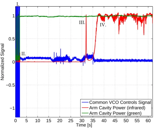
Lock acquisition of the recombined ITF: when the Fabry-Perot cavities are locked and the dark fringe power goes down a given threshold, usually half of the maximum power, the trigger

In the following, we describe in more detail the galaxy catalogs that we use, quantify the probability that the host galaxy for each event is in the galaxy catalog that is used for

Considering that the electromagnetic field is a special case of the gravitational field [10], the structure of which has the character of a standing gravitational wave for

We refer to this for- malism (or class of alternative theories) as a multiple Lagrangian framework because for these theories the trajectories of massive bodies (classical particles

To assign a systematic uncertainty from the model used to describe the detector resolution, the fits are repeated for each step replacing the Hypatia functions by bi- furcated

The low threshold discriminator gives the time reference (figure 6) as long as the delay between the avalanche precursor and the streamer signals is less than 10ns, as

L’archive ouverte pluridisciplinaire HAL, est destinée au dépôt et à la diffusion de documents scientifiques de niveau recherche, publiés ou non, émanant des

For example, we know that the two main operators of the quantum mechanics, the momentum operator p = ∂x ∂ and the position operator q = x, form a noncommutative algebra with