THE DESIGN OF AN INTUITIVE TEACHING INTERFACE FOR ROBOT PROGRAMMING BY HUMAN DEMONSTRATION
by
James Bassey Pinkney
S.B. Mechanical Engineering
Massachusetts Institute of Technology (1987)
Submitted to the Department of
Mechanical Engineering in Partial Fulfillment of the Requirements for the Degree of
MASTER OF SCIENCE atthe
Massachusetts Institute of Technology
May 1993 __
B.,f\e \c¥i3
j
@ 1993 Massachusetts Institute of Technology
All rights reserved
MASSACHUSETTS INSTITUTE OF TECHNOLOGY
.JUL 2 0
2001
LIBRARfESSignature of Author --:C:::...- ~ _+_. _
Department of Mechanical Engn(eering
\ I
May 7, 1993Certified by _
/
Accepted by --:= ...ll:ooO::cc:;;';"'O., ,
Pn5feSsor Harry West Thesis Supervisor
Professor Ain A. Sonin Chairman, Departmental Graduate Committee
by
James Bassey Pinkney
Submitted to the Department of Mechanical Engineering on May 7th, 1993 in partial fulfillment of
the requirements for the Degree of Master of Science
ABSTRACf
This thesis deals with the design and implementation of an intuitive, lightweight, compact, low-cost human interface for robot programming by human demonstration. The key feature of this robotic teaching device is its ability to allow the operator to transfer manual manipulation skills to a robot for the completion of contact tasks. The prototype incorporates 6 degree of freedom force and position sensing with tactile and grip position sensing. Total mass was a low 850 grams. Preliminary experimental results proved ease of use and very low error: 20.3 grf. average force error for a 1 Kgf. applied load, and 16.6 grf. average force error for a 3 Kgf. grip force.
Thesis Supervisor: Dr. Harry West
To My Father Joseph Udo Bassey
few years. Without them, the road would have been significantly more rocky.
To Harry West for providing the inspiration, opportunity, guidance, support, knowledge, wisdom and sense of humor I needed in both my academic and research efforts. Harry is, without a doubt, the best Professor I've ever met. To the GEM program, Harry West and Dean Isaac Colbert for securing funding for my research and academic studies.
To Nate Delson for his technical wizardry and for being an all around great guy. Nate's contributions to the design of the RTD are immeasurable.
Both Harry West's and Nate Delson's ideas and guidance contributed largely to any success I have had in the design of the RTD. My thanks to them. Thanks to all the people I've met in the M.I.T. community who have made my 6 years of being a student here wonderful. I have been priviledged to take classes and learn from some of the best professors in the country.
To Francis Zucker and TIona Kannel for being like a family to me. To Randy Jezowski and the guys Ramco for performing way above and beyond the call of duty. These guys are the best and most personable machinists on the planet.
To my friends and family, BTB, and my fellow students in 3-070. To Juliana Bassey and the Bassey family, and to Austin and Karen During and the During family. To Chuck Brown, Ernie Johnson, Elvie Antonacci, Hortense Pinkney, Veena Trehan and Quinetta. Last, but not least, to Pop - James Pinkney Sr.
Table of Contents
1.0 Introduction 9
1.1 A Guide tothe Thesis l0
1.2 Current Programming Techniques 11
1.2.1 Completing Contact Tasks Using Compliant Motion Control 13
1.2.2 Roootic Teaching IJevice 13
1.3 IJesign for the hUIllall hand 14
1.3.1 Gripper Task Comparison 15
1.3.2 GripJ>er Feature ComParlS()n 18
1.4 IJesign Altertlatives 20
1.4.1 Two Electric gripJ>ers 20
1.4.2 Spring Design 23
1.4.2.1 Grip force error in spring design 25
1.4.2.2 Applied force error in spring design 26
1.4.2.3 Why the spring gripJ>er design was not used 28
1.4.3 Teaching Glove with Fingertip Force Sensors 29
1.4.4 Multiple Roller Design 32
2.0 Inventing a Robotic Teaching Device - Three RIDs Built. 35
2.1 Tongs 35
2.1.1 Tongs Tactile Sensor Circuit 37
2.2 Motorized Gripper 40
2.2.1 Motor Control Circuit 41
2.3 Final RTD Design - 'lOfhe Bat" 42
3.0 I>esign Emlxx:iillleJlt 47
3.1 Force Sensor 47
3.2 Position sellS()r 47
3.3 Tactile Sensors 48
3.4 Grip Position Sensing 48
3.5 Rack and Pinion 48
3.6 Teflon bushings 49
3.7 Friction, Jamming and Bushing Placement. 49
3.7.1 Friction Effects, Case 1 - Bushings in Cart 50
3.7.2 Friction Effects, Case 2 - Bushings in Base 52
3.11 Cable Termination and Length Adjustment .56
4.0 IJesign, Details 58
4.1 Base -Rooot Side (Part No. 1-1) .58
4.3 Left and Right Carts (Part Nos. 1-3 and 1-4) 60
4.4 Left and Right Carts, Human Side (Part Nos. 1-5 and 1-6) 61
4.5 Base - Human Side (Part No. 1-7) 61
4.6 Handles (Part Nos. 1-8 and 1-9) 62
4.7 Potentiometer Support (Part No. 1-9) 62
4.8 Constant Force Spring Spool (Part No.1-II ) 62
4.9 Moving Pulley Bracket (Part No. 1-12) 62
4.10 Cable guideshaft (Part No. 1-13) 63
4.11 Spool Shaft (Part No. 1-14) 63
4.12 Pulley (Part No.1-IS) 63
4.13 Bird Support (Part No. 1-16) 63
4.14 Bearing Support - V and Bearing Support - H (Part Nos. 1-17 and 1-18) 63
4.15 Cable Terminator (Part No. 1-20) 64
4.16 Bird Bracket (Part No. 1-21) 64
5.0 Results 65
5.1 Experimental Results 69
5.1.1 Grip Force Error 69
5.1.2 Applied Force Error 71
6.0 Cone Iusions 75
6.1 Recol1'\IIlel\dations 76
Appendix A - Parts List 78
Appendix B - Machined Parts Drawings 79
Figure 1.4.1 Electric Robotic Teaching Device with Magnetic Slip Clutch 21
Figure 1.4.2 Motorized Robotic Teaching Device with Locking Mechanism 23
Figure 1.4.3 Spring-Based Mechanical Robotic Teaching Device 24
Figure 1.4.4 Model of Force Path in Springed Robotic Teaching Device 27
Figure 1.45 Teaching Glove with Fingertip Force Sensors and 6l)egree of Freedom
Posi tion Sense>r 30
Figure 1.4.6 Multiple Roller Robotic Teaching Device 33
Figure 2.1.1 Tongs - Robotic Teaching Device I. 36
Figure 2.1.2 Tactile Sense>r Hardware Block Diagram 38
Figure 2.1.3 Tactile Sense>r Hardware Schematic 39
Figure 2.2.1 Motorized Gripper - Robotic Teaching Device 11 40
Figure 2.2.2 Motor Control Circuit Schematic for Motorized RID .41
Figure 2.3.1 Conceptual Model of 'The Bat' - Robotic Teaching Device 111.. 43
Figure 2.3.2 Conceptual Views of PulleylCable System for 'BAT' Robotic Teaching
Device 45
Figure 3.7.1 Cartl Rack with Bushing in Cart. 51
Figure 3.7.2 Cartl Rack with Bushing in Ba~ 54
Figure 4.0.1 Exploded Isometric Assembly of "The Bat' Robotic Teaching Device 59
Figure 5.0.1 Front View of RID Prototype 66
Figure 5.0.2 Back View of RID Prototy}>e 66
Figure 5.0.3 RTD Prototype, Power Grasp 67
Figure 5.0.4 RID Prototy})e, Precision Grasp 67
Figure 5.05 Tongs, Motorized Gripper, and 'BAT' Robotic Teaching Devices 68
Figure 5.1.1 RID Prototype Force Readings Before Grip Force Application 70
Figure 5.1.2 RID Prototy})e Force Readings During Grip Force Application 70
Figure 5.1.3 RID Prototype Force Readings Before Force Application 73
Figure 5.1.4 RID Prototy})e Force Readings with 1 Kg Force in X-Direction 73
Figure 5.15 RID Prototy})e Force Readings with 1 Kg Force in V-Direction 74
1.0 Introduction
1.0 Introduction
A significant challenge that exists in the field of robotics today is programming a robot to perform a useful task. Industrial robots are currently taught tasks which control the position of the robot's end effector but not the force with which it contacts the environment, thereby greatly limiting the number of useful tasks that they may accomplish. Current industrial robots are also difficult to program (teach). Itis therefore highly desirable to design a human interface for teaching a robot to replicate human manual skills. The design of a compact, low cost, intuitive, easy-to-assemble robotic teaching device (RTD) for the completion of contact tasks is the subject of this thesis. It is hoped that this device will find future use in the factory, office, home and for telerobotic applications which would allow human manual manipulation skills to be transferred to a hostile or physically
inaccessible environment. This work is being conducted at the Mechatronics Design Laboratory in the Center for Information-Driven Mechanical Systems at the Massachusetts Institute of Technology.
Robots would have a significantly improved impact on the factory floor accomplishing flexible manufacturing operations if they could be quickly and easily taught by an operator to perform force-controlled tasks. A human interface device which could accomplish the teaching operation would make the job of manufacturing and inspection significantly easier and faster. The hardware necessary to perform assembly tasks is readily available, however, the bottleneck which prevents robots from performing useful tasks is the difficulty in programming them. This thesis deals with the design of a robotic teaching device which will greatly ease the programming process and allow
skills to the robot. The prototype is designed to be as easy to use as a pair of pliers. and the operator will not need to possess any robot programming skill. Only the skill of performing the task using the teaching interface will be required for successful robot instruction.
1.1 A Guide to the Thesis
1.0 Introduction. This chapter deals with the motivation and goals involved in designing a robotic teaching device (RTD), including a look at some robot control strategies, human factors engineering and RTD design alternatives. Itis intended that this chapter will show why there is an immediate need for an effective RTD in many robotic applications, as well as what design characteristics should be incorporated into the RID prototype to result in effective robot programming by human demonstration (RPHD).
2.0 Inventing a Robotic Teaching Device - Three RTDs Built. This section takes a conceptual look at the prototype robotic teaching device
designed and constructed for this thesis ('The Bat'), as well as two other earlier and different versions which were successfully built and used for some robot programming by human demonstration tasks. It also discusses why the final RTD prototype's performance should be superior to that of the earlier versions.
1,Q Introduction
3.0 Design Embodiment. The basic elements utilized in the design of the final prototype RTD.
4.0 Design Details. This section consists of a description of the design and construction details of the prototype.
5.0 Experimental Evaluation. An evaluation of the final prototype RTD's functionality.
6.0 Conclusions. This section discusses the conclusions based upon the experimental evaluation, as well as recommendations for future work and design improvements,
1.2 Current Programming Techniques
We will begin with a brief examination of current robot programming techniques. Current industrial robots are typically taught by means of a teaching box (lead through programming), walk-through programming, or via off-line programming. Lead-through programming, the most common method used to teach industrial robots, involves the operator leading the robot through the desired trajectory by depressing buttons to control the robot's linear motions and joint rotations. This method, which gives the operator immediate visual feedback on the robot's trajectory, tends to be time consuming due to the slow movement of the robot during the teaching
process. Walk-through programming involves the operator moving the robot's end effector through the desired trajectory. However, this method
hostile environment, walk-through programming might not be a viable option. Off-line programming involves the use of a robot programming language to teach motions which are subsequently downloaded to the robot controller. A detailed understanding of the task requirements is necessary to write a successful off-line program, as well as an understanding the robot programming language.
The aforementioned methods of robot programming tend to be slow, inflexible, unintuitive, and expensive, both in terms of down-time and the high cost of programming. Current industrial robots programmed using walk-through or lead-through programming are generally useful for relatively simple tasks, such as pick-and-place, arc-welding and spray
painting. However, there are many labor-intensive industrial tasks (such as assembly) which, in order to be automated, will require contact between the end-effector and its surrounding environment. In order to automate these tasks, the robot must somehow be taught dextrous manipulation skills, which require the end-effector to physically interact with the environment without causing damage to the part or the robot. Using position control alone, a relatively small error in positioning could result in extremely high forces on both the part being manipulated and the robotic end-effector. This is an intolerable situation that should obviously be avoided; incorporating
compliant motion control is a viable solution to the environmental contact problem.
I,Q Introduction
1.2.1 Completing Contact Tasks Using Compliant Motion Control
Compliant motion control is used to govern the mechanical interaction of the robot's end-effector with its environment. There are a variety of control methods which fall under the umbrella of compliant motion control: Passive and active compliance, active impedance control, and dynamic hybrid
control. All these control schemes can be used very effectively to perform a task, yet the control parameters must be fully understood and specified in the robot program in order to implement an effective compliant motion control scheme.
One method of robotic teaching is to take an analytic approach: understand the assembly situation's geometric and physical constraints and synthesize an appropriate control strategy. Then, using off-line programming, the
appropriate robot language may be generated to complete the task. This is a major challenge in robotics research since the appropriate analysis of even a relatively simple problem, such as inserting a part of irregular cross-section into a close-fitting hole, can be exceedingly complex. Analytic techniques can be inflexible, time-consuming, and extremely challenging if not impossible. Employing such techniques would almost certainly be impractical in a flexible-manufacturing industrial environment, being more the subject of advanced research,
1.2.2 Robotic Teaching Device
Another more immediately promising method of robotic teaching is to use an interface device which would gather teaching data from the human to be
Even young children are able to, without being consciously aware of it, effectively execute extremely complex compliant control strategies using manual manipulations that would elude even the most sophisticated, state-of-the-art research robot. Teaching these control strategies to a robot via a human interface device requires the measurement of the position, force and tactile data necessary to execute the task, i.e. gathering teaching data.
Although the human may not be neither aware of nor able to quantify the control strategies employed, by measuring and interpreting the teaching data the control strategy may be synthesized and the successful generation of the robot program may be accomplished.
This thesis deals with the design and construction of a compact, low cost, intuitive robotic teaching device (RTD). This device was designed to be an interface between the robot and the human, allowing the human to perform and thereby demonstrate the task to the robot, while the device's onboard sensors measure force, position, and tactile information. This data, in turn, is to be used to generate the robot program. The device is therefore intended to transfer human manual skills from an operator to a robot, so that the robot may find more widespread use in the office, home, and factory environments.
1.3 Design for the human hand
Since the robotic teaching device must be used by the human hand, there are a number of design considerations which must be accounted for. Factors such
1,Q Introduction
aesthetics were all considered in the design. It is readily apparent that features such as cost, weight, size, and stress on hand should be minimized and those such as ease of use, fit and aesthetics should be maximized. The device was also designed with ease of assembly as a high priority.
Let us briefly examine the human grasp. Some of the most common human hand grasping techniques are power grip, lateral pinch grip, three finger precision grip and palmar grip. Lateral pinch grip involves a thumb-forefinger side grip, three finger precision grip uses the thumb, index and middle fingers for grasping, palmar grip is a thumb-fingertip precision grip, and power grip consists of a grasp between the fingers and the palm. Power grip allows for the greatest force applied. For example, a 95th percentile male can produce a maximum power grip of 164 lb., while the maximum pinch grip would be 48 lb.. Biomechanical stress on the hand should be held to a minimum, while still allowing for a variety of grasps, so that the desired precision or power may be applied to a given task.
Bent-wrist tool use should be held to a minimum to avoid unnecessary hand fatigue and, over prolonged use, carpal tunnel syndrome (as an extreme
example). Maximum grip strength is reduced by 20% or more from the use of gloves.
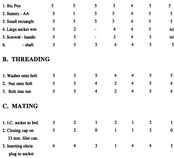
1.3.1 Gripper Task Comparison
In order to help evaluate desirable tool characteristics to be incorporated into the robotic teaching device's design, a number of tasks were performed with various tools and the ease of task completion was rated on a five point scale. The human hand was compared to six tools as listed in Table 1.3.1. The tools
(parallel-jaw gripper with springs to force jaws normally closed), pliers, a small vise, a pair of Vise-gripsTM with flat, rectangular grips, and a motor-driven parallel jaw gripper,
These tools have in common the ability to grasp parts of different shapes with varying degrees of difficulty; they are distinguished by the shape of the gripping surface, the presence (or lack) of a locking mechanism, weight and size. Additionally, the grip movement may involve parallel motion, such as in a vise, or an angular motion about a fixed point, as in a pair of pliers.
The experiment yielded some interesting results which helped to guide the RTD design. Clearly, both minimizing the tool's weight and size, as well as balancing the tool, eased tasked completion. Inmany instances, the locking mechanism found on, for example, vise-grips, also facilitated task
completion. Finally, the cross-sectional shape of the grip surface influenced the ease with which the part could be gripped and, therefore, the task
Table 1.3.1 Gripper Task Comparison
I,Q Introduction
EASE OF TASK COMPLETION
FOR EACH GRIPPER
(1.5, 1 = Very difficult, 3 = nominal, 5 = easiest, '.' = Impossible)
Hwnan Vise-Grip C-Clamp Pliers Mini- Vise-Grip C-Clamp
TASKS
Hand Tongs Springed Vise Aat Motor-Dr
---A. PICK AND PLACE
1. Bic Pen 5 5 5 3 4 5 5
2. Battery - AA 5 1 5 3 4 5 5
3. Small rectangle 5 5 5 3 4 5 5
4. Large socket wm 5 2 4 4 5 n/a
5. Screwdr - handle 5 5 3 4 5 n/a
6. - shaft 5 3 5 4 4 5 5
B.
THREADING
1. Washer onto bolt 5 3 5 4 4 5 5
2. Nut onto bolt 5 5 4 2 4 5 4
3. Bolt into nut 5 5 4 2 4 5 4
C. MATING
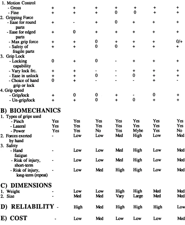
1. I.C. socket tobrd. 3 2 1 2 1 2 1 2. Closing cap on 5 2 0 1 1 2 0 33 mm. film can. 3. Inserting electro 4 4 3 1 4 4 3 plug tosocketA number of features were evaluated for each tool type examined to identify general manual control, biomechanical, dimensional, cost and reliability characteristics, as shown in Table 1,3.2.
Each tool allowed the user varying degrees of mechanical control over the part being manipulated. Gross and fine dextrous control of the part, the ability to grasp parts of varying shape and fragility, the maximum force one may exert, the locking capability and grip/release speeds were evaluated. This control was in part a result of the ease with which various grips (pinch,
lateral, power) could be employed.
Other biomechanical characteristics such as the force exerted by the hand to complete a task, and the safety over both short and long-term usage were evaluated. Finally, the weight, size, reliability and cost of the tools were examined,
This admittedly quick study revealed that the flat vise-grips were generally equal or superior in performance to the other tools evaluated due to the following design characteristics: Low weight, flat, essentially parallel motion grips, a reasonably large grip span, good balance, and a locking mechanism. They allowed the user to fairly easily grip parts of varying shape with good dextrous control, providing good tactile feedback. The positive characteristics of the flat vise grips, as well as the other tools, were carefully weighted in the design of the robotic teaching device.
Table 1.3.2 Gripper Feature Comparison
1.0 Introduction
PARAMETERS
Hwnan Vise-Grip C-Qamp Pliezs M' ,lIU- Vise-Grip C-Clamp(+, -,0 =nominal) Hand Tongs Springed Vise Aat Motor-Dr
--- ...
---A) CONTROL
1. Motion Control -Gross + + + + + + + - Fine + + + 0 0 + + 2. Gripping Force- Ease for round + + 0 + + +
parts
- Ease for edged + 0 + + + + +
parts
- Max grip force + + 0 + + + 0/+
- Safety of + + 0 0 + + + fragile parts 3. GripLock - Locking 0 + 0 + + + capability - Vary lock frc. + + + + + - Ease in unlock + + 0 0 + + - Choice of hand 0 + + grip or lock 4. Grip speed - Grip/lock + 0 0 + 0 + - Un-grip/lock + + 0 + 0 + +
B) BIOMECHANICS
1. Types of grips used
- Pinch Yes Yes Yes Yes Yes Yes Yes
- Lateral Yes Yes Yes Yes Yes Yes Yes
-Power Yes Yes No Yes Mybe Yes No
2. Forces exerted Low Low Med High Low Med
by hand 3. Safety
-Hand Low Low Med High Low Med
fatigue
- Risk of injury, Low Low Med High Low Med
short-teon
- Risk of injury, Low Med High High Low Med
long-tenn (repeat)
C) DIMENSIONS
1. Weight Low Low High High Med MOO
2. Size MOO Med Vary large Med Med
D) RELIABILITY
-
High Med High High High Low1.4 Design Alternatives
A number of design alternatives were considered as possible robotic teaching device candidates. They were carefully evaluated and weighted for their benefits and drawbacks. Even if a design were rejected, whatever positive features could be extracted were considered for the final RTD design.
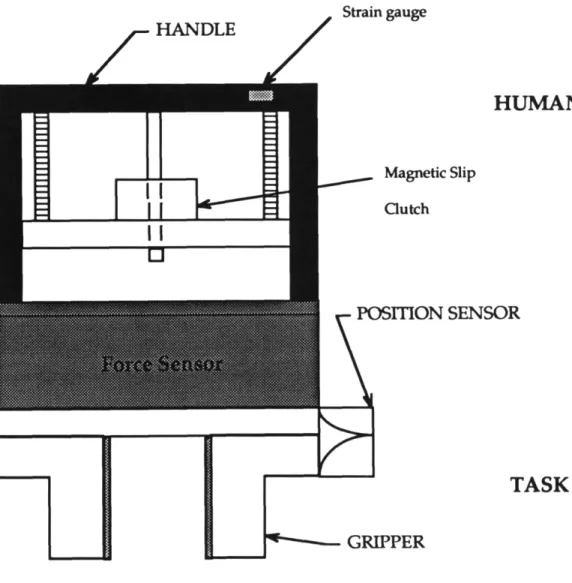
1.4.1 Two Electric grippers
Two variations on a similar design proposed consisted of electro-mechanical grippers. See Figure 1.4.1. The key distinguishing features of the first device examined were:
1) Use of standard 6 degree of freedom force sensor (Zebra Robotics) and 6 degree of freedom electro-magnetic position sensor (Bird).
2) Strain gauge on handle. Used to measure the grip force applied by human hand.
3) Magnetic slip clutch on human side to exert a braking force against the hand when the part is gripped.
4) Motorized gripper on task side.
5) Tactile sensor to give feedback on applied force on task side. This force would be regulated to correspond to the force measured by the strain gauge on the human side.
This design was rejected in its conceptual stage for two reasons. The first is because this RTD proposed could exert a braking force on the hand but it could not exert a compliance force. A good example is to imagine a rubber
1.0 Introduction
ball being gripped. As itis gripped, it compresses and exerts a force back on the hand. Now, if one were to reduce the force applied to the ball it would decompress and still push against the hand. Inthe electric gripper setup, if
Strain gauge
HUMAN SIDE
Magnetic Slip GutchTASK SIDE
~--~ GRIPPERagainst the hand; it can only dissipate force applied. There is a solution to this problem: By adding an additional actuator (motor) on the human side of the gripper, one could duplicate the impedance of the gripped part actively. This device is depicted in Figure 1.4.2.
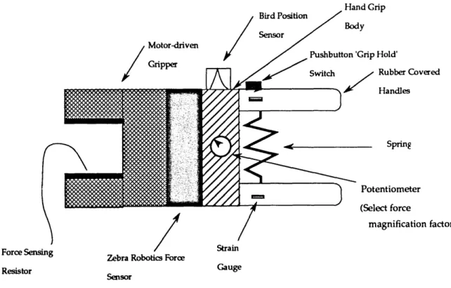
The second electric gripper is similar to the aforementioned in the use of force, position and tactile sensing except for a few important changes. Firstly, the handles on the human and task sides move in parallel, so that a one-to-one relationship between the position of the task side grips and the human side grips. A constant force spring is used to force the handles into a normally open position. Since the grip force is created actively (via actuators on the task side) a potentiometer may be used to select a force magnification (or
reduction) factor; the factor may also be set so that a one-to-one
correspondence between the force exerted on the human side handles is identical to that on the task side grips. Also, an electronic locking mechanism may be incorporated so that the device can clamp down on a part, similar in operation to a pair of Vise-GripsTM.
I,Q Introduction / Motor-driven Gripper ForceSensing Resistor
Zebra Robotics Force Sensor Strain Gauge Hand Grip Body Spring Potentiometer (Select force magnification factor)
Figure 1.4.2 Motorized Robotic Teaching Device with Locking Mechanism
The second problem with the design is the use of magnetic components,
specifically the motor to actuate the task side gripper's opening and closure, as well as the magnetic slip clutch. Both components would adversely affect the Bird position sensor's accuracy to the extent that their use should be avoided if at all possible.
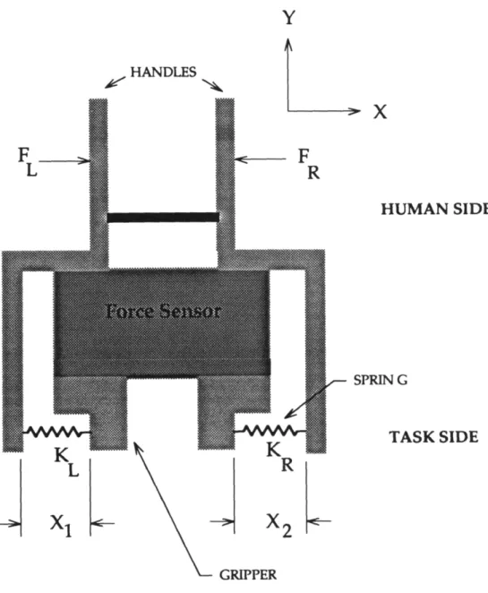
1.4.2 Spring Design
One design evaluated (Fig. 1.4.3 ) involved the use of horizontally mounted springs on the RTD task side to effect the transfer of the grip force exerted on
the arms attached to the springs would move in, compressing the springs and thereby applying the closing force to the carts on the task side.
y
F_~
L ¥HANDLES~F
R HUMAN SIDE SPRING TASK SIDE1.0 Introduction
The goal, naturally, is to have any force exerted on the task side grips
reflected back to the force sensor. The force required to grip the part should not show up as a force sensor reading. Since the springs on the task side are to be used solely for task side cart opening and closure, which involves forces only in the horizontal direction, these springs may be attached to the RTD so that they exert resistance only in the horizontal direction, as opposed to the vertical. The force exerted in the horizontal direction will be evaluated for possible errors.
1.4.2.1 Grip force error in spring design
We may see from the free body diagram of the springed RTD in Figure 1.4.3 that if the grips open and close symmetrically:
and
where
LFX=O
FL
=
Grip force exerted on left cart FR=Grip force exerted on right cart(1.4.1)
(1.4.2)
Inthe absence of backlash, and if the spring constants KL and KR of the left and right carts, respectively, are equal, then since:
and
(1.4.3)
we may conclude that
(1.4.5)
and there is no error due to the grip force exerted on the human side. This, naturally, is what is desired. Due to backlash, however, FLwill not equal FR
because one cart will displace before the other when a force is initially applied and a force error, Ferrmay be calculated as:
So we see that if the system is without backlash and symmetric, ~Xl =AX2 and the error vanishes. As Kg is reduced, the effects of this error would be
minimized.
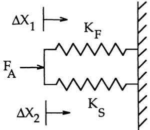
1.4.2.2 Applied force error in spring design
Errors in the force sensor reading in the springed gripper design may result from both backlash and the difference in stiffness between the force sensor and the springs. An applied force has two force paths: through the force sensor and through the springs. We may model the system very simply (assuming the engaged rack and pinion system is infinitely stiffer than either the force sensor or the springs) as two springs in parallel, as shown in Figure
1,0 Introduction
Figure 1.4.4 Model of Force Path in Springed Robotic Teaching Device
In the absence of backlash, because of geometric constraints,
and
or
where
FA
=
KSAX + KFAXFA
=
(KS + KF) aXKF =Stiffness of the force sensor
FA=Force applied by environment on task side
(1.4.7)
(1.4.8)
So we see that if:
then
(1.4.10)
However, we must consider that error is further compounded by backlash, where AXt ~ AX2. So,
FA =KSAXt + KFAX2 (1.4.11)
In this case we see that backlash would cause AXt to be greater than ~X2, further increasing error. Again, making Ks very small compared to KF would still minimize this error effect.
1.4.2.3 Why the spring gripper design was not used
Now that it has been shown that the spring stiffness KS must be small compared to the force sensor stiffness KF in order to minimize error, the springed RTD design may be properly evaluated.
1,0 Introduction
It is apparent that a one to one relationship between the position of the human side grips and the task side grips would not be maintained for a gripped part since the springs would have to compress in order to exert a grip force, As the amount of grip force applied to a rigid part is, for example, increased, the human side grips would close even though the task side grips would not. Additionally, the springs would introduce a 'spongy' feel, i.e. the compliance of the gripped part would be in series with the compliance of the springs in the RTD. This would make it difficult, if not impossible, for the human to distinguish between the compliance in the part itself and the compliance introduced by the springed RTD gripping mechanism.
It is more desirable to design an RTD in which the human is able to detect whether a part is rigid or compliant. Very stiff springs, or even rigid rods, would accomplish this but, as shown earlier, the price paid in resulting errors would be unacceptable.
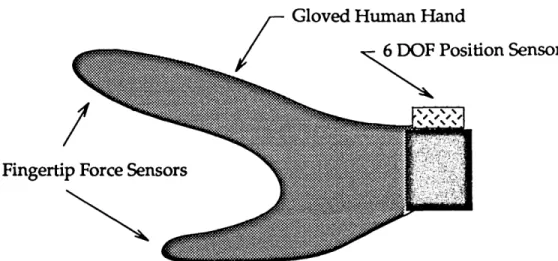
1.4.3 Teaching Glove with Fingertip Force Sensors
One Robotic Teaching Device design evaluated involved using a glove to be
worn on the human hand, equipped with 6 degree of freedom position
sensing, as well as fingertip force sensors. See Figure 1.4.5. This interface has the potential to be an extremely intuitive RTD because the operator would, ideally, be able to perform and thereby teach the robot any task that could be accomplished using one or both hands.
Fingertip Force Sensors
r
Gloved Human HandI
~
Position SensorFigure 1.4.5 Teaching Glove with Fingertip Force Sensors and 6 Degree of Freedom Position Sensor
The human hand offers the capability of executing fine motion control due to its ability to accomplish a large variety of grasps that would elude
conventional robotic grippers, Industrial robotic grippers are available for many different applications, the most common variety being parallel and angular two-jaw grippers. These grippers may also be modified for picking up parts of varying cross-section, such as round parts.
The use of robotic fingertip sensors has found some successful use in research applications. Lorentz et. al. have written of a 4 degree of freedom robotic fingertip sensor which would provide force feedback information for
1,0 Introduction
as compliant as human flesh, allowing it to potentially be used in applications similar to those that the human hand may accomplish,
The Stanford JPL hand employs fingertip sensors used effectively to
accomplish a wide variety of grasping and fine manual manipulation. This device offers tremendous potential for use in industrial applications provided it can be effectively programmed, or taught, to do a variety of useful tasks. It
is the teaching of such a device, via analytic techniques or by human
demonstration, that is the real bottleneck in preventing its widespread use in industry. Therefore a device analogous to the Stanford JPL hand, used for teaching, would be a very valuable commodity.
However, in designing a robotic teaching device one is forced to examine two important criteria: Cost and practicality. Current industrial robots do not employ such advanced end effectors as those with articulated hands (devices with two or more joints used to grasp and manipulat~ objects). We were highly motivated to design a robotic teaching device which would have immediate, practical application on the factory floor, if not the office and home. Furthermore, robotic fingertip sensors are expensive: for our application the cost of each sensor would have been approximately $4000. These sensors are fairly fragile, they are not designed for high loads, and are not particularly shock resistant. Additionally, the human hand can perform manual manipulations which could easily elude the conventional two-jaw gripper and, regardless, the analytic transformation between force
information gathered with a teaching glove to a successful two-jaw gripper manipulation would be extremely complex.
As a result, itwas concluded that the RTD should be similar in its
manipulation, if not identical, to the conventional and common two-jaw parallel gripper. This greatly simplifies the transformation of teaching data into the robot program. To summarize, the examination of using a glove-like teaching interface helped reveal the benefits of maintaining a one-to-one relationship between the teaching device's motion and that of the
conventional parallel two-jaw robotic gripper. The development of a glove-like teaching device will no doubt be the subject of future research
development which will lend itself to teaching the robot to accomplish a wide variety of tasks where flexible grasping and fine manipulation is necessary.
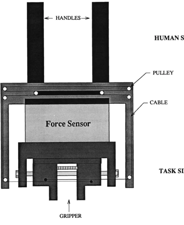
1.4.4 Multiple Roller Design
One design evaluated involved the use of multiple rollers (pulleys) in combination with a cabling system to transfer the grip force exerted by the hands on the human side to the task side, so that a part may be gripped. See Figure 1.4.6. Itis of paramount importance that the grip force is not reflected
1.0 Introduction
HUMAN SIDE
PULLEY
TASK SIDE
GRIPPER
pulley system and provide a rigid grip force transfer path. However, due to the large number of pulleys frictional losses would occur which would
introduce an error between the grip force applied on the human side and the resulting grip force exerted on the task side. Itis therefore desirable to reduce, if possible, the number of pulleys in the robotic teaching device while still taking advantage of the cabling/roller force transfer mechanism.
2,0 Inventing a Robotic Teaching Device 2.0 Inventing a Robotic Teaching Device - Three RTDs Built
Three robotic teaching devices were constructed in the Mechatronics
Laboratory for Robot Programming by Human Demonstration (RPHD). The devices built were:
1) Tongs with position sensing
2) Motorized gripper with position and force sensing
3) Mechanical gripper with position and force sensing, as well as grasped part impedance feedback.
As the RTD evolved through its various design stages, an attempt was made to incorporate the most salient features of earlier designs into the final RTD product. Human interface design is a particularly challenging task,
particularly due to the interdisciplinary nature of the design tools employed. A knowledge of precision machine design, electro-mechanical systems, and human factors is integrated into the design process. A conceptual description of the three robotic teaching devices developed follows.
2.1 Tongs
The simplest implementation of the robotic teaching device consisted of a set of plastic tongs equipped with tactile sensing (force sensing resistors) and 6 degree of freedom position sensing (Bird). The tongs were designed to be lightweight, to fit comfortably in the human hand, and to be easy to make. ~ Figure 2.1.1.
steel pipe and using a heat gun to soften the material so that it could be bent into the U-shaped tong form. Since Plexiglas™ is a thermoform material, it
may readily
Plastic Tongs
Position Sensor :
Bird - electromagnetic
Force Sensing
Resistor
2.0 Inventing a Robotic Teaching Device
be heated and deformed into the desired curved shape. As shown in Figure 2.1.1, the strip was curved in three places to yield the desired shape.
Two holes were then drilled in the sides of the tongs for mounting the Bird™ magnetic position sensor on the side. A pair of GE force sensing resistors were mounted along the inside of the tongs on each side near the bottom using adhesive rubber strips cut to size.
The position information gathered from the Bird position sensor, as well as the tactile sense information, is stored and used to generate the robot
program. The human uses the tongs to perform a task in his workspace and the robot then duplicates the motions in its own workspace. Since no force information is gathered (besides tactile sensing), the robot is generally limited to position-controlled tasks, since relatively small positioning errors against a rigid surface could result in large, undesirable forces.
The tongs were found to be quite effective in teaching pick-and-place tasks.
2.1.1 Tongs Tactile Sensor Circuit
Tactile sensing is accomplished by the use of force sensing resistors (FSRs) mounted inside the arms of the tongs, as shown in Figure 2.1.1. We will briefly examine the tactile sensing electronic interface to the computer's
digital I/O board. The circuit block diagram is shown in Figure 2.1.2, and the hardware schematic is shown in Figure 2.1.3.
Placing the FSR in series with another resistor (Rm) provides a voltage
divider. The output voltage is amplified via a 741 op-amp wired in negative feedback. The gain of the circuit is determined by the resistor values chosen
FSR SIGNAL (VOLTAGE DIVIDER)
INVERTING AMPUFIER (741 OP.AMP)
DIGITAL INPUT (COMPUTER BOARD)
2.0 Inventing a Robotic Teaching Device (Gain
=
-R2/R1). This amplified output is sent to the input of a Schmitt trigger (using a comparator) circuit; the sizing of resistors R3 and &tdetermine the voltage trigger point for the digital output and, through hysteresis, prevents multiple transitions (switch debouncing) due to noise about the trigger point. The digital output is then sent to an input line on the computer's digital I/O board. The output signal normally hi due to the pull-up resistor
&S.
As a result, when a part is picked up or released by the tongs, the I/O board reads a digital transition and tactile sensing is achieved.
+sv
+sv
+sv
Digital
Output
This RTD consisted of a two-jaw parallel gripper equipped with 6 degree of freedom force and position sensing. It is cable-driven motorized gripper with a fixed, joystick-like handle with a thumb switch that controls the gripper's opening and closure. See Figure 2.2.1.
Bird Position Sensor
2,0 Inventing a Robotic Teaching Device Let us examine the motor control circuit used to power the gripper motion,
2.2.1 Motor Control Circuit
This circuit is constructed in a "H-bridge" arrangement so that, depending on the RTD thumb switch position, either one or the other diagonal "arm" of the circuit is energized so that the DC motor is capable of reversing direction, See Figure 2,2,2, +15V 680Kn 24Kn 680Kn .4Kn 30
,oa--DO-e.---'
r
+5VSimple transistor switches (Ql, Q4 and Q2, Q3) are used to switch current in the circuit. A kickback diode is wired in parallel with the motor to clamp down the voltage spikes caused by the motors inductive switching load, so that the switching transistors' base inputs are not overloaded and damaged. We may upon examination of the circuit in Figure 2.2.2 see that if the single pole double throw switch is closed in one position, transistors Ql and Q4 are activated, resulting in clockwise motor rotation. Conversely, if the switch is closed in the opposite position, transistors Q2 and Q3 are energized and the motor turns in the opposite, counter-clockwise direction. The use of an
inverter on the switch signal input is necessary so that only one arm of the H-bridge circuit is activated at any given time.
2.3 Final RTD Design - ''The Bat"
This robotic teaching device, which we will refer to as 'The Bat', is designed to be optimal within the existing design constraints. It is equipped with six degree of freedom force and position sensing, tactile sensing, and grip position sensing. See conceptual model in Figure 2.3.1.
2.0 Inventing a Robotic Teaching Device
Figure 2.3.1 Conceptual Model of 'The Bal' - Robotic Teaching Device III
The Bat is an essentially mechanical RTD interface to the real world, so that the impedance of the gripped part is mechanically reflected back to the operator's hand. There is a one-to-one relationship between the position of the handles on the human side and the position of the grippers on the task side. There is also a one-to-one relationship between the grip force applied to the handles and the resulting grip force acting on the part, with a slight linear
open position and friction,
A foremost design requirement of the Bat RTD is that there should be no force sensor readings due to applied grip force. When the part is gripped and no external forces are applied:
~ Fx,y,z
=
0 ~ Mx,y,z=
0A novel feature of this device is its use of a cable/roller system a bracket to "reach around" the force sensor and transfer the grip force applied at the handles to the task side grips without introducing a force sensor reading. As shown in Figure 2.3.2, a central roller is pulled by the grip force Fgso that a
resulting, closing force is exerted on the grips; FL and FR. The pulleys are aligned on all parts the Bat RTD so that the grip force is not transferred to the force sensor as a false force sensor reading.
2.0 Inventing a Robotic Teaching Device
Fg
Top View
Cart
Side View
Figure 2.3.2 Conceptual Views of Pulley/Cable System for IDA TI
Robotic Teaching Device
(303 stainless steel, black anodized aluminum, brass, delrin) so that the Bird position sensor, which is susceptible to magnetic interference errors, is allowed to perform accurately.
The device is equipped with two sets of handles; long and short. This allows for the convenient use of a variety of grasps. The longer handles lend
themselves to a power grasp (though not exclusively), while the shorter handles are better suited for more precise grips such as lateral pinch, three finger precision, and palmar grip.
The task side grips are identical in dimension to the Mitsubishi Movemaster robot located in the Mechatronics Laboratory at M.I.T. so that part referencing may be accomplished.
3,0 Design Embodiment
3.0 Design Embodiment
A number of basic elements were incorporated into the final RID design (the Bat), which are described in the following sections.
3.1 Force Sensor
A six degree of freedom Zebra Robotics force sensor is used to gather force and moment data: FX1 Fy, Fz, MX1 My, Mz. This force sensor was chosen because of
its low cost ($2500), rugged construction, standard, small package (66 mm. diameter x 35 mm. thick, availability, and low weight (640 gf). Its hardware and software package make it simple and quick to interface to the computer.
Itcan detect forces as small as 10 grams or as large as 20 kilograms.
3.2 Position sensor
The Bird six degree of freedom electro-magnetic position sensor used to gather translational and rotational position (P", Py, Pz, Rx, Ry, Rz). It consists of a receiver/transmitter package with a 2 ft. translational range, and an angular range of +/-180 degrees azimuth and roll, as well as +/- 90 degrees elevation. It has a translational accuracy of 0.03 in. RMS at 8 inches, 0.1 in. RMS overall. It has an angular accuracy of 0.1 degree RMS at 8 inches, 0.5 degree RMS overall. The small receiver (1"xl"xO.8") may be easily mounted on the robotic teaching device for gathering position data.
Interlink™ force sensing resistors are used to provide tactile sensing, as in the tongs and motorized gripper designs described in Chapter 2. This one degree of freedom force sensing resistor (FSR) has the property of changing its resistance continuously from 400 Kn to 40 Kn, depending on the force applied, making them ideal for tactile sensing.
3.4 Grip Position Sensing
A ceramic potentiometer attached to the human side base, connected to the pinion shaft via a timing belt is used to detect how far open the grips are. Timing belt pulleys are attached to both the potentiometer and the pinion shaft.
3.5 Rack and Pinion
Linear cart motion is achieved via a rack and pinion system which is used on both the human and task sides to assure both parallel gripper motion and the symmetric opening and closure of the grips about the base center. The pinion shaft is held rigidly by two stacked roller bearings located in the middle of each base.
Round racks are used to both bear load and assure parallel motion of the carts. Two racks are used. Each rack is attached rigidly to one of the carts and passes through a teflon bearing on the other cart. Teflon bushings mounted inside the base support each rack at two ends, so that the rack is always supported at
3.Q Design Embodiment
the base. This way, a relatively large moment arm counteracts the moment applied and prevents frictional effects such as jamming.
3.6 Teflon bushings
Teflon (Te-F-Thane™) bushings were used because of their low static and dynamic coefficients of friction - the static coefficient of teflon sliding on steel is 0.04. Thomson™ linear bearings have a lower coefficient of friction but were not chosen due to their undesirable magnetic properties which would interfere with the Bird's performance.
3.7 Friction, Jamming and Bushing Placement
In designing the BAT RTD, jamming of the carts on their shafts must be avoided and friction effects must be minimized. We will examine the effects of friction in the BAT RTD due to the placement of the bushings about which the racks linearly translate. We may choose the bushing location to be either in the carts or in the base. In case 1, bushings in carts, the cart translates along the rack. In case 2, bushings in base, the art is fixed to the rack and the rack translates along the base. Either configuration results in parallel, symmetric motion about the gripper center. A brief friction analysis will help reveal that the optimal bushing placement is in the base.
3.7.1 Friction Effects, Case 1- Bushings in Cart
Consider the placement of the bushings inside the cart body so that the carts slide with respect to the racks, which are fixed. An examination of the free body diagram in Figure 3.7.1 and a force and moment analysis about point A
yields:
where MA
=
Moment about point AFH
=
External force acting on cartL
=
Distance from center of rack to FH R2=
Downward reaction forceWe
=
Cart width(3.7.1)
So we know that:
Now, we know the friction force FF
(3.7.2)
and N F H R 1 3,Q Design Embodiment (3.7.4)
T
whereFigure 3.7.1 Cart! Rack with Bushing in Cart
R1
=
Upward reaction force Jl=
Static coefficient of frictionSince Rl
=
R2, substitution yields:Fp
=
2JlFH/We (3.7.5)We see that increasing cart width We reduces the friction force acting against linear motion of the cart along the rack.
3.7.2 Friction Effects, Case 2 - Bushings in Base
In this configuration the placement of the bushings in the base results in improved performance due to greatly reduced friction effects. The analysis is similar to Case I, bushings in cart. An examination of the free body diagram in Figure 3.7.2 and a force and moment analysis about point Byields:
where ~ Fx
=
FH -FF=
0 ~ Fy=
Rl - R2=
0 ~M=
-FHL +R2WB (3.7.6) (3.7.7) (3.7.8)Since we know that
and
we may substitute to yield:
3,0 Design Embodiment
(3.7.9)
(3.7.10)
t4---w--- ....
B
R 1F
H
R 2Figure 3.7.2 Cart! Rack with Bushing in Base
So it is readily apparent that since WB» We, placement of the bushings in
the base results in greatly improved performance over placement of the bushings in the carts.
3.7.3 Eliminating Jamming
We will briefly the extreme case of friction, the jamming condition. Jamming occurs when:
3,0 Design Embodiment
or, conversely, sliding occurs when:
(3,7.13)
So we may conclude, using Eq. 3.11, that if:
(3.7.14)
the carts will slide on the racks. We know or can assume the values of WB,L
and J.1.. We will assume a large L
=
4 in. to correspond to the long set of handles where FH would be offset a relatively large distance.WB
=
3.25 in. L =4 in.=0.04
Substituting into Eq. 3.14, we see that WB > 0.32 by an order of magnitude, and therefore cart jamming should not be a concern.
A stranded fiber cable such as SPECTRATM or Berg-Fibre™ (Aramid fiber) cable was used because of its ability to pass around small diameter pulleys, its high modulus, low elongation and high resistance to self-abrasion.
3.9 Pulley/roller Bearings
Delrin pulleys were custom made to press fit over small (0.175 in. o.d. x 0.0937 in. wide) roller bearings. This pulley/bearing system minimizes friction effects due to cable loading, as well as cable wear due to the low friction coefficient of Delrin.
3.10 Constant Force Springs
Constant force springs are used to pull the gripper carts into a normally open position. The pulley arrangement is such that both the human side and task side grips are forced open so that a one-to-one correspondence between their respective positions about the gripper center is maintained.
3.11 Cable Termination and Length Adjustment
The fiber cable used to transmit grip force is terminated at the carts by
knotting the end and epoxying it into a brass terminator with a small hole to pass the cable through and a ledge to support the cable knot. On the task side, the cable passes through a hollow 4-40 screw before termination. This is a cable length adjustment screw which may be turned on either of the two task
3.Q Design Embodiment
side carts to effect cable tensioning. This adjustment is designed to take up any cable slack caused by stretching or creep.
This chapter details the design features which of the parts which were custom made by Ramco in Salem, MA. The parts are referred to by part number, and the actual machine drawings may be referenced in Appendix A. The
exploded isometric assembly shown in Figure 4.0.1 will help clarify the design details discussed in the following sections.
4.1 Base - Robot Side (Part No. 1-1)
This part supports the symmetric and parallel motion of the left and right carts on the task side. The constant force springs force the grips into a normally open position and are mounted on spools on the two "arms" extending out from the robot base side. These constant force springs are attached to the carts' sides using 2-56 nylon screws. Two binding head screws mount the base to the force sensor. Four .0.25" long Teflon bushings
mounted in the sides of the base bear load and provide smooth, linear travel of the carts. The also bear all loads acting on the carts. Two stacked roller bearings mounted in the middle of the base support the pinion shaft in a stable manner so that rack tooth under loading skipping is avoided. The base sides are extended for cosmetic purposes so that rack motion beyond the bushings is hidden. The bushing holes were wire electro-discharge machined (EDM) in order to provide linear concentricity and, as a result, smooth cart travel.
4,Q Design Details
4.2 Bracket (Part No. 1-2)
The bracket is used to support the cable/roller mechanism and to transfer the grip force applied on the human side to the task side grips (carts), The bracket is designed to that the grip force is not read by the force sensor. The 0.093" diameter through holes are used to mount the bearing supports, which position and support the pulleys mounted on roller bearings. Two 0.129" through holes are used to mount the bracket to the force sensor, The bracket is designed so that the pulleys are in line with the racks, thereby eliminating friction effects due to moments caused by off-axis forces.
4.3 Left and Right Carts (Part Nos. 1-3 and 1-4)
These parts act as the task side grips, that is, they grip the part being
manipulated by the operator. An angular "widget" located on the cart sides, designed by Randy }ezowski of Ramco, is used to tighten the rack against the carts, aligning the racks vertically and allowing for a horizontal adjustment. The carts are designed to have the same dimensions as those on the
Mitsubishi Movemaster robot in the Mechatronics Laboratory at M.I.T., so that accurate part referencing may be accomplished. Two "arms" located on the cart sides have threaded holes in them. In these holes are cable tension adjustment screws. Two holes on the cart sides provide attachment points for the constant force springs used to force the carts into a normally open
position. Each cart has both a hole for rack attachment and a hole for a Teflon bushing used to allow free rack passage.
4.Q Design Details
4.4 Left and Right Carts, Human Side (Part Nos. 1-5 and 1-6)
These parts are analogous to the aforementioned Part Nos. 1-3 and 1-4. They also have blind screw holes on the top for attaching the long and short
handles (Part Nos. 1-8 and 1-8 Rev2). These screw holes are positioned so that the handles do not touch when the grips are fully closed, and a "lip" makes the bottom of the handle align flush with the top of the cart.
4.5 Base - Human Side (Part No. 1-7)
This part is analogous to the aforementioned Part No. 1-1. Itis taller due to the fact that a timing belt pulley is also located on the pinion shaft under the pinion (spur gear) head, thereby moving the position of the pinion head up. The timing belt is attached to a pulley mounted on a ceramic potentiometer, so that the grip position may be sensed. Two 2-56 screw holes mounted on the sides of the base provide an attachment point for two horizontal bearing supports (Part No. 1-18) on which a bearing and pulley are mounted. This supports the cable travel path so that closing the human side grips in turn closes the task side (robot) grips. Three 2-56 through holes provide
attachment points for Part No. 1-9, the Potentiometer Support. As in Part No. 1-1, two roller bearings are lightly pressed into the middle of the base so that the pinion shaft may be supported stably. Two 4-40 screw holes provide an attachment point for the force sensor. The Bird may be mounted using 10-32 UNF-2B screws under either "wing" of the base, or on the Bird Bracket (Part No. 1-21), which attaches to the potentiometer support.
These are handles which screw into the human side carts and provide a grasping mechanism for the operator. The come in two grip lengths: 3.75" and 1.7". The former lends itself to a power grasp; the latter to more precise two- and three-finger grasps. A 0.25" long "lip" at the top of the handles supports against slipping due to gravity.
4.7 Potentiometer Support (Part No. 1-9)
This part is attached to the human side base and is used to mount a
potentiometer with a timing belt pulley. This potentiometer is used to detect gri p position.
4.8 Constant Force Spring Spool (Part No.1-II)
This spool is used to mount the constant force springs onto the robot side base.
4.9 Moving Pulley Bracket (Part No. 1-12)
This part provides cable attachment points and pulley/bearing mounting. The cables in the bracket/cart system (human and task sides) loops around a pulley mounted in this bracket. The two moving pulley brackets travel on either side of the bracket (Part No. 1-2), and are attached to each other with a single cable which loops around the bracket.
4.Q Design Details
4.10 Cable guideshaft (Part No. 1-13)
This part is used to support the pulley/bearing located in the moving pulley bracket described above.
4.11 Spool Shaft (Part No. 1-14)
This part is used to support the constant force spring spool's attachment to the robot (task) side base.
4.12 Pulley (Part No. 1-15)
These pulleys are mounted on tiny roller bearings and are used to provide a friction-minimized cable travel path. The low-friction Delrin pulley material also minimizes cable abrasion.
4.13 Bird Support (Part No. 1-16)
This part is used to provide a 1in. standoff from all metal of the Bird position sensor, so that position error may be minimized. The Bird is mounted to 8-32
UNC-2B through holes on the Bird support, which is, in turn, mounted on the RID.
4.14 Bearing Support - V and Bearing Support - H (Part Nos. 1-17 and 1-18) Used to mount the pulley/bearing combination and provide precise
This part is used to terminate the cable after passing through the arms on either the human or task side carts. The cable is passed through a 0.63" hole and knotted. This knot rests against a ledge with a 0.90" diameter hole to accommodate the knot. The knot is epoxied into the ledge hole to provide extra strength.
4.16 Bird Bracket (Part No. 1-21)
This part is used to attach the Bird to the RTD so that interference from nearby metal is minimized. Note, as mentioned before, there are two other Bird attachment points which offer more aesthetic appeal. This part is
mounted using 0.129" through holes to the potentiometer support. The Bird, mounted on the Bird Support, is in turn attached to the Bird Bracket.
5.0 Results
5.0 Results
The robotic teaching device prototype (The Bat) was assembled and found to perform excellently. Smooth, low-friction travel, good balance and feel, and a low total weight of 850 grams (1.87 LB) characterized the device. The front and back views of the RID prototype are shown in Figures 5.0.1 and 5.0.2, respectively.
As predicted, the longer handles lend themselves to a power grasp, as shown in Figure 5.0.3, and the shorter handles are better suited to more precise two and three finger grasps, as shown in Figure 5.0.4.
The tongs, the disassembled motorized gripper, and the prototype RTD are all shown in Figure 5.0.5.
5,0 Results
Figure 5.0.3 RTD Prototype, Power Grasp
5,Q Results
5.1 Experimental Results
The 'Bat' RTD prototype was tested to determine two primary characteristics: 1) Grip force not detected by force sensor
2) Forces applied in x, y, or z directions are accurately detected by the force sensor.
The results are detailed below.
5.1.1 Grip Force Error
A 3 Kgf. grip force was applied to the handles and the resulting detected forces were printed out. Figure 5.1.1 shows the force sensor reading (Kgf.) before the grip force was applied. The forces and moments are shown pictorially, with the center representing no force applied, and the actual forces are printed out at the bottom (F", Fy and Fz, respectively).
Figure 5.1.2 shows the force sensor reading with the 3 Kgf. grip force applied.
As Figures 5.1.1 and 5.1.2 show, there is little change in the detected force sensor values. The change in force in the x-direction was -10 grf., the change in force in the y-direction was -40 grf., and the change in force in the z-direction was 0 grf. These values fall very much within the accuracy of the test method, so one may conclude that the grip force is indeed not detected by the force sensor.
.ilt-*.~
~urrent torce vectoY: U,i~ -0. L':j i). 4.:J
...
f ..0.,,,, ~.; I
Mv
Figure S.LI RTD Prototype Force Readings Before Grip Force Application
**
** *i(- 0;(-*
oA-*.jt-*
ok'*
*****************
*
*.*
***
5.Q Results
5.1.2 Applied Force Error
The 'BAT' robotic teaching device prototype was tested for accuracy by
clamping it vertically in a vise, holding it in place by the human side base. A 1 Kgf. force was then applied in the +x, -y and -z directions using a scale. The resulting forces detected by the force sensor were printed out. We will use the convention that Fx,Fy and Fz represent forces applied in the x, y and z
directions, respectively.
Figure 5.1.3 shows the RTD force sensor reading without any applied force.
As we can see in Figure 5.1.4, the 1 Kgf. force applied in the +x direction
results in a Fxchange from 0.07 Kgf. to 1.07 Kgf., which is completely accurate. The y- and z-forces are relatively unchanged.
Looking at Figure 5.1.5, the 1 Kgf. force applied in the -y direction results in a Fychange from -0.30 to -1.28 Kgf., or a 20 grf. discrepancy between applied and detected forces; this is more than acceptable. The y- and z-forces are relatively unchanged.
Figure 5.1.6 shows that a 1 Kgf. force applied in the -z direction results in a Fz
change from -0.20 to -1.27 Kgf., or a 70 grf. discrepancy between applied and detected forces, which, again, is quite acceptable given that the test method was not the most accurate, but was chosen for convenience. The x and y forces are relatively unchanged.
detection accuracy and can therefore be used to perform useful contact tasks. Any errors presently existing in the prototype can be corrected in software.
5.0 Results
... ,,/
.~:..~.
("'/v
i"lz
~urYent torce vector: C). ()I ~-(). :.:::4 -u. :.:~U
I
--Figure 5.1.3 RTD Prototype Force Readings Before For~eApplication
***************************************~ r'y rz ~ly
**
*"*
**-:**
-ill' -:Ji-*~.
.:.**
~k-;<-it-*-f',*'*Lurrent torce vector: I. U / -O.:.:iU -0. :...::.::~
~v**************************************
CuYren~ force vec~or: '-(). U'::J -U.Ub
Figure 5.1.5 RTD Prototype Force Readings with 1 Kg Force inY-Oirection
*
********
rz**************************************
*****
rly MZCurrent force vector: O.U/
***
**
6.0 Conclusions
6.0 Conclusions
The final RID prototype (the Bat) was designed, machined, assembled, tested, and found to have excellent performance characteristics. All components were fully functional. The device has a low mass (0.85 Kg.), is easy and
intuitive to use, simple in design, easy to assemble and low in cost. The total cost of all machined components (Appendix B) was less than $2000.
The tension adjustment was found to work very well in combination with the extra bracket length, making cabling the RID prototype a fairly
straightforward procedure. The choice of handles allows for a number of different grasps, which should increase the variety of useful tasks which may be accomplished using the device.
The low friction throughout the Bat RID prototype insures full functionality, no jamming even holding the ends of the long handles, and therefore
minimizes the errors encountered in part impedance feedback to the hand.
As was the original design goal, the RID prototype offers six degree of
freedom force sensing, six degree of freedom position sensing, tactile sensing and grip (cart) position sensing using the potentiometer/timing belt system.
The experimental results showed that rather little applied and grip force error was present in the device. The average applied force error was found to be 20.3gri. for the 1 Kgf. load applied in the x, y, and z directions. The average grip force error was 16.6gri. for the 3 Kgf. grip force. The values are more
As with any device to be used by the human hand, minimizing the weight is a primary concern. The use of lighter components in the RTD prototype's construction, such as a combination of magnesium, Delrin and aluminum (where higher strength is necessary, such as in the bracket) would be a large step in reducing weight.
The friction forces in the device could be reduced by using custom made Thomson™ linear bearings, substituting the non-magnetic 303 stainless steel for the magnetic steel used in the current bearing design so that interference with the Bird™ magnetic position sensor would not occur.
A cable adjustment mechanism on the human side, and possibly one along the outside of the bracket (between the vertically mounted pulleys) would allow for greater, more symmetric cable length adjustment.
The constant force spring strength could be increased to allow for easier grip closure, although this would be at the cost of introducing a larger force offset at the human side handles and, effectively, reducing part impedance feedback. Alternatively, one of the handles could be modified to add fingerholes so that gripper opening and closure could be more easily accomplished. This would, from a functional standpoint, be similar to holding one handle in a lateral
6,0 Conclusions pinch grip and using the middle and/or ring finger to effect gripper opening and closure.
De-magnetizing the RID prototype's steel components regularly could help minimize interference with the Bird™ position sensor.
The task side carts should be modified so that various grip shapes may be easily attached and detached, so that differently shaped parts can be gripped and part referencing to a robot with a differently dimensioned gripper could be easily accomplished.
The use of cable materials other than the BergTMfiber cable could reduce creep and increase cable stiffness, should the aforementioned characteristics become a concern. Kevlar™, Spectra™, and Vectran™ are all possible candidates with differing creep and stiffness characteristics whose performances could be superior to the BergTMcable.
Fortunately, all of the aforementioned changes would be fairly easy and inexpensive to implement. The Bat RID should be a very useful teaching interface for robot programming by human demonstration using compliant motion control strategies. It is hoped that this device will greatly ease the task of teaching industrial and research robots to do useful tasks at a far lower cost than with conventional programming methods.
Quantity Part Number Distributor Description
1 8TP2-14 Berg Timing Belt Pulley (.349" 0.0.)
1 8TP2-24 Berg Timing Belt Pulley (.609" 0.0.)
1 8TB-44 Berg Timing Belt
6 Q1-9 Berg Retainer (Snap) Rings
1 S1o-9T Berg Retainer Ring Applicator Tool
1 S1-37 Berg Stainless Ground Stock (3/32")
1 S1-8 Berg Stainless Ground Stock (l/8")
1 PR-D-6 Berg DelrinRod Stock (3/8'*)
1 PR-D-4 Berg Delrin Rod Stock (1/4")
2 R2-20 303 ST/ST Berg Round Rack, 96 Pitch
2 P96S4-34 Berg Spur Gear, 96 Pitch
1 AA034-SOFf Berg Fiber Cable (1/32")
2 Y6-S4-A6 Berg Flathead Screws
2 YIO-S4-AS Berg Binding Screws
2 N2-A2-ZS Berg Nylon Fillister Screws
2 NII-A12-ZS Berg Nylon Fillister Screws
2 B8-7 Berg Teflon Bearings
2 B8-6 Berg Teflon Bearings
8 B8-5 Berg Teflon Bearings
1 SOF8973-1OK Newark Conductive Plastic Pot.
10 FAG SR0612ZZ Alpine Bearing Roller Bearing (3/16" 0.0.)
4 FAG SR2ZZ Alpine Bearing Roller Bearing (3/8" 0.0.)
Appendix B - Machined Parts Drawings