--4
Computational Framework for Simulating the
Deformation and Fracture Response of
Oligocrystalline
Shape Memory Alloys
by
Zhiyi Wang
B.S.E., Shanghai Jiaotong University (2015)
Submitted to the Department of Aeronautics and Astronautics
in partial fulfillment of the requirements for the degree of
Master of Science in Aeronautics and Astronautics
at the
MASSACHUSETTS INSTITUTE OF TECHNOLOGY
September 2018
@
Massachusetts Institute of Technology 2018. All rights reserved.
Signature redacted
Author...
...
Department of Aeonautics and Astronautics
.. une 21, 2018
Certified by...Signature
redacted
- ThailRadovitzky
Professor of Aeronautics and Astronautics
Thesis Supervisor
Signature redacted
Accepted by ...
Hamsa Balakrishnan
Associate Professor, Aeronautics and Astronautics
Chair, Graduate Program Committee
MASSACHUSETTS INSTITUTEWOF TECHNOLOGY
uCt
092018
Computational Framework for Simulating the Deformation
and Fracture Response of Oligocrystalline Shape Memory
Alloys
by
Zhiyi Wang
Submitted to the Department of Aeronautics and Astronautics on June 21, 2018, in partial fulfillment of the
requirements for the degree of
Master of Science in Aeronautics and Astronautics
Abstract
Shape memory alloys (SMAs) are a class of metallic materials that can recover their original shapes when heated above a certain temperature. Unique features including the superelasticity and shape memory effect have made SMAs attractive materials for a variety of fields ranging from bioengineering to aerospace engineering.
In polycrystalline forms, the desirable properties of SMAs have been significantly limited by severe premature intergranular fractures at grain boundaries. Chen et al.
(2009) showed that the intergranular fracture in Cu-based SMAs can be mitigated
in fine wire forms with bamboo-shaped oligocrystalline microstructure. Tensile tests conducted in the oligocrystalline systems show that large ductility limits approaching those of a single crystal can be achieved while avoiding the issues involved in single crystal processing. It is, thus, of great importance to investigate how the microstruc-ture and grain boundary characteristics affect phase transformation of oSMAs and how to delay transformation-induced fractures.
In this thesis, an anisotropic single-crystal constitutive model is developed to study the underlying mechanism of transformation-induced fracture in oSMAs from a numerical perspective at the microstructural level. The model is based on the micromechanical constitutive framework by Thamburaja and Anand (2001) and a ro-bust explicit integration scheme is developed to update the constitutive law. In order to investigate the effects the grain boundary characteristics have on the martensitic phase transformation and transformation-induced fracture, finite element simulations are performed for modeling the stress-strain response and martensite-austenite phase transformation under uniaxial tension loading condition for oSMA wires with triple junction structures. A quantitative analysis of the simulation results is conducted at the microstructural level in each transformation system to interpret the initiation of transformation-induced fracture. The simulations provide insights on the mechanical response, energy absorption of oSMA wires, as well as shed light on the microstruc-tural design objectives of oSMA to avoid or delay the intergranular fracture.
Thesis Supervisor: Ranl Radovitzky
Acknowledgments
First I would like to express my deepest gratitude to my advisor Rail Radovitzky, for giving my the opportunity to conduct research in such an interesting field and for his consistent support, guidance and encouragement throughout the years. I am deeply grateful that Rail has always believed in my potentials and helped me to set and reach higher goals in research and life. Thank you Rail, you have helped me to grow into a better researcher and a better person.
My sincere thanks go to Dr. Aurlie Jean, Dr. Martin Hautefille and Dr. Adrian Roselen for making me feel welcomed upon my arrival at the group and for their invaluable contributions to SUMMIT. Thank you Adrian for your generous help in this endeavor. I would also like to thank Dr. Khai Pham and Dr. Yang Liu for their instructions and guidance. Thank you Khai for helping me to get a better grasp of the code and encouraging me to dive deeper into programming. Thank you Yang for always taking the time to answer my questions and care about me in so many ways. I also want to express my thanks to Brian Fagan and Thomas Fronk for their friendship and their interests in my progress; I have always enjoyed our talks!
I would also like to thank the past and current members of RR group, including Mohammad Islam, Michael Braun, Dr. Ryadh Haferssas, Dr. Bianca Giovanardi, Anwar Koshakji, Brad Walcher, and Adam Sliwiak for making the group such a friendly and collaborative environment.
I would also like to express my gratitude to Prof. Christopher Schuh and Dr. Nihan Tuncer for their invaluable experimental work and instructions in this endeavor. My thanks also go to Beth Marois from the AeroAstro Department and Janka Moss from the ISO. I am extremely grateful for their consistent patience, support and help.
I am also thankful to my dear friends from college and childhood, Naxian Ni,
Guodong Chen, Shun Zhang, Kaidi Lu, Yutong Zhang, and Yichen Rao, for their
company and friendship in this journey.
for their unconditional love and support throughout the years. I love you and could not have done this without you!
Contents
1 Introduction 15
1.0.1 Experimentally Observed Mechanical Response of
Oligocrys-talline SM As . . . . 18
1.0.2 Previous Work on Numerical Modeling of SMAs . . . . 23
1.0.3 Thesis Objectives and Approach . . . . 27
2 Constitutive Modeling of SMA Based on the Geometrically Nonlin-ear Theory of Transformation 29 2.1 Anisotropic Rate-dependent Constitutive Model of Single-Crystal SMAs 29 2.1.1 Decomposition of the Deformation Gradient . . . . 31
2.1.2 The Geometrically Nonlinear Theory of Martensitic Transfor-m ation . . . . 33
2.1.3 Balance of Linear Momentum . . . . 37
2.1.4 Balance of Angular Momentum . . . . 39
2.1.5 Balance of Energy . . . . 39
2.1.6 Entropy Imbalance . . . . 40
2.1.7 Free Energy . . . . 41
2.1.8 Constitutive Equation for Elastic Stress . . . . 41
2.1.9 Phase Transformation Flow Rule . . . . 42
2.1.10 Transformation Conditions . . . . 43
2.1.11 Rate-dependent Theory . . . . 45
2.1.12 Rate-dependent Flow Rule . . . . 46
2.3 Explicit Constitutive Update Algorithm for Martensite Phase
Trans-form ation . . . . 47
2.4 Constitutive Tests of Material Responses under Different Loading Con-ditions . . . . 51
2.5 Modeling of the Temperature-Dependence of Phase Transformation in a Single-Crystal SM A . . . . 55
3 Computational Framework for the Simulations of Boundary Value Problems 59 3.1 Finite Deformation Formulation of Governing Equations . . . . 60
3.2 Finite Element Framework and Implementation in SUMMIT . . . . . 61
3.2.1 Spatial Discretization . . . . 61
3.2.2 Time Discretization . . . . 63
4 Finite Element Simulations of the Deformation of Oligocrystalline SMAs with Triple Junction Structures 65 4.1 Examination of Ductility Limits of Oligocrstalline SMA Wires Using Continuous Galerkin Formulation . . . . 66
4.1.1 Quantitative Analysis of Martensitic Transformation in Each Transformation System around the Triple Junction . . . . 72
4.1.2 Quantitative Analysis of Martensitic Transformation in oSMAs with Different Grain Orientations . . . . 79
4.2 Examination of Ductility Limits of Oligocrstalline SMA Wires Using Discontinuous Galerkin Formulation . . . . 88
List of Figures
1-1 Stress-temperature phase diagram and cyclic loading stress-strain re-sponse of SM As . . . . 16 1-2 Stress-strain curves of Cu-based SMAs with different grain structures.
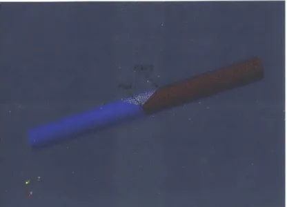
The schematics in the top right corner show the grain structure of each sam ple [611 . . . . 20 1-3 Stress-induced martensite morphology near a triple junction in a wire
with a diameter of 150 pm under tension in the horizontal direction. The light gray bands highlights the variants of martensite and the contrast of the martensite phase has been enhanced for visual clarity. [6 11 . . . . 2 1
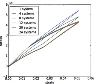
2-1 Austenite-twinned martensite microstructure: RjgU and Uj represent variant pairs that satisfy the kinematics compatibility equation [28 . 34 2-2 Material behaviors under cyclic loading at different temperatures . 52 2-3 Stress-strain response under cyclic loading with different number of
different transformation systems . . . . 53 2-4 Stress-strain response under cyclic loading with different critical
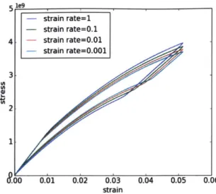
driv-ing forces . . . . 54 2-5 Stress-strain response under cyclic loading with different strain rates . 55 2-6 Comparison of the stress-strain response at different temperatures with
4-1 Mesh for an oSMA wire containing 28835 tetrahedral elements gener-ated by Gmsh. Different colors represent grains with different orienta-tions. Point 1 is an example of the triple junction point. . . . . 67 4-2 Martensite volume fraction and shear stress S12 distribution in the
oSMA wire at E = 1% . . . . 68
4-3 Tensile stress S33 distribution in the oSMA wire at c = 1% . . . . 69
4-4 Martensite volume fraction and shear stress S12 distribution in the
oSMA wire at c = 6.5% . . . . 69
4-5 Tensile stress distribution S33 in the oSMA wire at c = 6.5% . . . . . 70 4-6 Martensite volume fraction and shear stress S12 distribution in the
oSMA wire at E = 7% . . . . 70
4-7 Tensile stress S33 distribution in the oSMA wire at c = 7% . . . . 71
4-8 Martensite volume fraction (left figures) and its increment (right fig-ures) in each transformation system at different strain levels along the triple junction line . . . . 75 4-9 Martensite volume fraction (left figures) and its increment (right
fig-ures) in each transformation system at different strain levels along the triple junction line . . . . 76 4-10 Martensite volume fraction (left figures) and its increment (right
fig-ures) in each transformation system at different strain levels along the line starts from Point 2 in Figure4-lMesh for an oSMA wire containing 28835 tetrahedral elements generated by Gmsh. Different colors rep-resent grains with different orientations. Point 1 is an example of the triple junction point. figure.caption.17 and is parallel to the x-axis . . 77 4-11 Martensite volume fraction (left figures) and its increment (right
fig-ures) in each transformation system at different strain levels along the line starts from Point 2 in Figure4-lMesh for an oSMA wire containing 28835 tetrahedral elements generated by Gmsh. Different colors rep-resent grains with different orientations. Point 1 is an example of the triple junction point. figure.caption.17 and is parallel to the x-axis . . 78
4-12 Mesh for an oSMA wire containing 31936 tetrahedral elements gen-erated by ICEM CFD. Different colors represent grains with different orientations . . . . 80 4-13 Case 1: Martensite volume fraction in each transformation system
along the triple junction line . . . . 82 4-14 Case 1: Stress tensor components (Pa) distribution along the triple
junction line . . . . 83 4-15 Case 2: Martensite volume fraction in each transformation system
along the triple junction line . . . . 84 4-16 Case 2: Stress tensor components (Pa) distribution along the triple
junction line . . . . 85 4-17 Case 3: Martensite volume fraction in each transformation system
along the triple junction line . . . . 86 4-18 Case 3: Stress tensor components (Pa) distribution along the triple
junction line . . . . 87 4-19 Mesh for an oSMA wire containing 6024 tetrahedral elements
gener-ated by ICEM CFD. Different colors represent grains with different orientations . . . . 89 4-20 Tensile stress distribution at E = 3% . . . . 90
List of Tables
2.1 Variants of the transformation systems for NiTi [16, 2] . . . . 35 2.2 Variants of the transformation systems for CuZnAl [27, 40, 451 . . . . 36 4.1 Rotation matrices correspond to the left, middle and right grain in
Figure 4-12Mesh for an oSMA wire containing 31936 tetrahedral ele-ments generated by ICEM CFD. Different colors represent grains with different orientationsfigure.caption.28 . . . . 80 4.2 Rotation matrices correspond to the left, middle and right grain in
Figure 4-19Mesh for an oSMA wire containing 6024 tetrahedral ele-ments generated by ICEM CFD. Different colors represent grains with different orientationsfigure.caption.36 . . . . 90
Chapter 1
Introduction
Shape memory alloys (SMAs) are a unique class of metallic materials that can recover their original shape when heated above a certain temperature. This effect is known as the shape memory effect, and it was first discovered in the 1950's in Cu-based alloys by Chang and Read
191.
SMAs also exhibit superelasticity which is a reversible elastic response to an applied stress under cyclic uniaxial loading at a constant temperature. SMAs have two stable phases: austenite and martensite. Austenite is stable at high temperature and exhibits high symmetry in its lattice structure. Martensite is stable at low temperature and exhibits low symmetry in its lattice structure. SMA's unique properties come from its ability to undergo reversible diffusionless solid-to-solid phase transformation from austenite to martensite. Phase transformation in SMA involves an abrupt change in the lattice structure without breaking the atomic bonds. The lattice symmetry of martensite highly depends on the components of the alloy. For example, in a NiTi alloy, the cubic austenite phase transforms to a shear-like distorted-monocinic martensite phase. In CuAlNi, there exist five phases: 03, 73, 33, j33, o. The #3 phase is of cubic symmetry and referred to as the austenite phase. Four different martensite phases can be formed based on the composition of the alloy and stress state. In this work we focus on phase transformation from /3,the cubic austenite phase to 73, the orthorhombic martensite phase in CuAlNi. In the unloaded state, shape-memory materials are distinguished by four char-acteristic temperatures: 0ms, martensite start temperature; 0mrf, martensite finish
I
~rn
f - - - - - - - - - - - - - --- - - - - - - - - - - - - - - -Uf .s--- -- - ---.----~af
--Ormf GMs Gas Gaf
T
Figure 1-1: Stress-temperature phase diagram and cyclic loading stress-strain re-sponse of SMAs.
temperature; 0as, austenite start temperature; and a!, austenite finish temperature.
SMAs exhibit superelasticity when undergoing cyclic loading at a constant
tempera-ture G > a!. The austenitic phase is stable while the martensitic phase is metastable
when the temperature 0 > Ga. When loaded from the stress-free state, an SMA
first deforms elastically until stress reaches a critical value Y+ and the forward phase transformation from austenite to martensite initiates. Once the forward transforma-tion is complete and the SMA is in the fully martensitic phase, it continues to deform elastically if subjected to further loading. Subsequent unloading from the purely martensitic phase leads to the reverse transformation from martensite to austenite when stress reaches another critical value Y_. The reverse transformation completes with the SMA returning to a purely austenitic phase and subsequent unloading to the zero-stress state leads to a complete shape recovery, but with a large flag-shaped hysteresis loop and net energy dissipation.
The hysteresis in the stress-strain curve is due to the difference between loading and unloading paths and is a unique byproduct of martensitic phase transformation. It can be explained by the internal friction generated by the motion of sharp interfaces
between the austenite and martensite phases
[641.
The shape and other qualitativefeatures of the hysteresis loop are highly dependent on the loading rate and the temperature. In principle, it is possible to design the material microstructure to increase the hysteresis loop and achieve larger energy dissipation, which makes SMAs
extremely attractive materials for the purpose of energy absorption.
An SMA that is initially in the austenite phase exhibits shape memory effect when undergoing isothermal cyclic loadings at a lower temperature 0ms < 0 < 0af. Upon loading, the forward transformation from austenite to martensite initiates when stress reaches the critical value Y. Further loading from the purely martensitic phase leads to elastic deformation. Yet upon unloading to the zero-stress state, the SMA does not recover its original shape until heated above the austenite finish temperature 0 > 0af.
This phenomenon is known as shape memory effect.
If the temperature is lower than the martensite finish temperature, 0 < Omf, the material is initially in the martensite phase. Most research is directed to SMAs that are initially in the austenite states, however, it is worth mentioning that superelas-ticity and shape memory effects can also be observed in SMAs that are initially in the martensite phases. Instead of phase transformation, the inelastic strain observed in an initially martensitic SMA is caused by reorientation of the martensitic variants when subjected to cyclic loading [431.
Unique features like the superelasticity and shape memory effect have made SMAs attractive materials for a variety of fields ranging from bioengineering to aerospace engineering. Shape memory alloy products have been widely used and continue to be a success in the biomedical industry. Practical use of SMA technology include artificial bones, stent devices for arteries and veins, dental wires, etc [371. SMAs also have found their ways into the aerospace industry as candidates for active materials as the industry continues to push for smart structures and intelligent systems [251.
SMAs are also used as thermal sensors and actuators due to their abilities to respond to temperature changes with shape changes.
The NiTi alloy is indisputably the market-dominant shape memory material as the vast majority of current applications of SMAs employ NiTi. However, the past few decades have witnessed increasingly intensive investigations of other SMAs, consid-ering the obstacles of working with NiTi due to oxidation of titanium, poor machin-ability of the alloy and the high raw material cost. The Cu-based SMAs including CuAlNi have attracted researchers' interests as alternatives to NiTi for some
appli-cations, given that the components of the alloy do not oxidize as easily as titanium, they are easy to manufacture and the material cost is substantially lower. Despite the lack of biocompatibility observed in CuAlNi comparing to NiTi, CuAlNi has been considered as a potential alternative material for non-medical applications [131. A detailed review of SMAs and their applications can be found in the work by Jani,
Leary, Subic, & Gibson (2014) [291.
1.0.1
Experimentally Observed Mechanical Response of
Oligocrys-talline SMAs
In this section, we review the experimental studies on the mechanical responses of
Cu-based SMAs in [11, 10, 61, 621. Single crystalline Cu-based SMAs exhibit unique
ductility as there is no internal constraint in the form of grain boundary to limit the martensitic transformation. Large deformation on the order of 10% has been experi-mentally observed without intergranular fracture in [611. Yet single crystalline SMAs are expensive and time-consuming to manufacture in bulk and the processing cost is too high for large-volume applications. The most common SMAs used in industry come in polycrystalline forms. However, in this case, the notable high ductility limits of Cu-based SMAs are significantly compromised by severe premature intergranular fracture originated at triple junctions [61, 62]. This embrittlement problem has lim-ited the application of polycrystalline Cu-based SMAs to cases involving small strains and low numbers of load cycles.
To overcome the issue of brittle intergranular fracture, Schuh et al. have de-veloped a continuous processing technique that produces Cu-based oligocrystalline SMAs (oSMAs) in thin wire forms[61J. The oSMA wire is essentially a string of longitudinal grains that arrange themselves in a bamboo-shaped structure and meet at grain boundaries. A very important characteristics of oSMAs is that most of the grains in the wire have very large free surface area, which allows for unimpeded phase transformation subjected to loading. Compared to polycrystalline SMAs, the bamboo-shaped oSMA wires have significantly larger grains and fewer triple
junc-tions with the total free surface area largely exceeding the total intergrain boundary area. As a result, oSMAs exhibit much higher ductility limits when compared to their polycrystalline counterparts. Tensile tests have shown that oSMA wires can en-dure significantly larger strain on the order of 7% [611. Furthermore, the ability of an
SMA to dissipate energy is found to be significantly enhanced in the form of these thin
wires [611. Ueland, Chen, and Schuh (2012) analyzed the various possible physical origins of this effect and concluded that free surfaces enhanced the internal frictional work associated with removing the martensite/austenite phase boundaries [61].
Ueland et al. investigated the mechanical properties of SMAs in different crys-talline forms to show the superiority of oSMAs compared to polycryscrys-talline ones [611. Figure 1-2 is reproduced from [61] where Ueland et al. compared the stress-strain responses of SMAs in the forms of single-crystal, polycrystal, near-oligocrystal and oligocrystal [61]. As can be clearly observed, a single crystalline SMA exhibits the most desirable mechanical properties and can tolerate significantly large strains while a polycrystalline SMA suffers from brittle fracture at a small strain level. Surpris-ingly a bamboo-shaped oligocrystal with no triple junction can survive large strains approaching those of a single crystal. This extremely important finding shows that with carefully designed microstructure of SMAs, desirable mechanical properties can be achieved at a much lower production cost, as well as with less processing
restric-tions compared to single-crystal processing
[61].
However, not all oSMAs have the ideal grain structures like those shown in Fig-ure 1-2(c) and some do contain triple junctions. In a more recent paper by Ueland and Schuh, they experimentally investigated the effect of grain constraints on martensitic transformation of as-cast oligocrystalline CuAlNi wires with different grain bound-ary characteristics [621. As discussed in the paper, an explanation for the brittleness of polycrystalline Cu-based SMAs is that transformation strains in adjacent grains are incompatible. The forced incompatibility leads to stress concentration at grain boundaries and triple junctions, which will eventually lead to intergranular fracture.
A major conclusion from their experiments is that the occurrence of martensitic
200 -(A) POLYCRYSTAL
~150
100 -(0 150 . (B) NEAR OUGOCRYSTAL 100-50U
ISO (C) OGOCRYSTAL 2100.150
0
OW-(D) SINGLE CRYSTAL
ro200-Stirain (%)
Figure 1-2: Stress-strain curves of Cu-based SMAs with different grain structures.
The schematics in the top right corner show the grain structure of each sample
[61]
orientations, but also with respect to different regions of the wire, in the sense that
the transformation is not uniform in the wire, and some regions transformed to the
martensite state before others. They also observed that phase transformation is
ex-tremely sensitive to grain boundary characteristics. Specifically, the transformation
is multi-variant and constrained in the grain boundaries and triple junctions, while it
is single-variant and unconstrained in regions that are farther from grain boundaries.
Another important finding is that the martenite-austenite morphology complexity
near triple junctions is much higher than that near grain boundaries and
(a)
14
%
(b)
2.6%
(C)
3.9%
(d)
4.3%
Figure 1-3: Stress-induced martensite morphology near a triple junction in a wire
with a diameter of 150 Mm under tension in the horizontal direction. The light gray
bands highlights the variants of martensite and the contrast of the martensite phase
has been enhanced for visual clarity. [611
strained monocrystalline regions. As shown in Figure 1-3, a new martensite variant
starts to grow at the triple junction in the small upper center grain when stress
increases from (a) to (b). This variant is presumably the most favorable one with
respect to the loading axis, i.e., it has the largest resolved shear stress. In panel (c),
a new variant is observed in the lower left grain, followed by the growth of many new
plates of this variant. It appears to replace the first variant to become the dominant
one. We can also observe the crossing of variants in the boundary of the small upper
center grain. Ueland and Schuh argue that, at grain boundaries, as stresses build up due to the incompatibility of transformation strains, the first variant is no longer favorable for transformation as its strain energy penalty becomes too large [621. It can also be seen that phase transformation is partial in the triple junction region and the plates of variants do not grow to connect with their neighbors, and later on the larger plates even split into smaller plates as shown in panels (b) to (c).
Ueland and Schuh postulate that the intergranular fracture in polycrystalline and oligocrystalline SMAs are induced by the large orientation-dependence of transforma-tion strains [621. This viewpoint was proposed by Sakamoto and Shimize (1986) and was supported by analytical and experimental studies [50, 491. Sakamoto and Shimize demonstrated that the transformation-induced intergranular fracture is due to the large strain incompatibility coming from the high anisotropy of the material [50, 491. Specifically, the fracture occurs in grain boundaries when phase transformation on one side of the grain boundary cannot be accommodated by that in adjacent grains to accommodate the strain. Hence the multi-variant morphology of the martensite transformation observed in Ueland and Schuh (2013) speaks of stress concentrations due to grain boundary constraints [621. Eventually, the stress concentrations near triple junctions will result in intergranular fracture. Therefore triple junction is con-sidered to be the most detrimental configuration in the oligocrystal microstructure leading to fracture.
1.0.2
Previous Work on Numerical Modeling of SMAs
The intriguing properties of SMAs have motivated intensive studies in the develop-ment of constitutive models of SMAs in the past few decades. Constitutive models are extremely valuable in helping to understand complex material behavior as they de-scribe how materials respond to general loadings. They can be incorporated in finite element methods to conduct numerical simulations. The last few decades have seen intense efforts in the development of constitutive models to describe the deformation behavior of SMAs. Smith (2005), Lagoudas (2008) and Khandelwal and Buravalla
A more recent review of constitutive models can be found in Cisse, Zaki and Zineb (2016) [121. Generally speaking, the models can be categorized into two groups:
con-tinuum based models and atomistic models. The concon-tinuum mechanics-based models can be then broadly classified into two categories: macroscopic phe-nomenological models and micromechanical models.
Macroscopic continuum mechanics models usually assume a macroscopic energy function that depends on state and internal variables. Internal variables are chosen to measure the degree of martensitic transformation, and evolution equations for marten-site are postulated to describe the process of phase transformation. Most macroscopic phenomenological constitutive models adopt such a thermodynamic structure, and martensitic volume fraction and transformation strain are often selected as internal state variables to describe the degree of transformation. Gillet, Patoor and Berveiller
(1998) proposed to utilize a J2 - J3 transformation surface to capture the
differ-ent behaviors of SMAs when subjected to tension and compression [201. Qidwai
and Lagoudas (2000) proposed a transformation function based on J2 - J3 - I1
invariants to account for the experimentally observed tension-compression asymme-try in SMAs [471. Other plasticity-inspired constitutive models for SMAs can be found in [8, 24, 261. Qiao (2013) [461 developed a non-local isotropic constitutive model by integrating the strain gradient plasticity theory by Anand et al. [1] into lo-cal thermomechanilo-cal formulations for phase transformation developed by Boyd and Lagoudas [8]. The model was applied to study size effects of CuAlNi and NiTi pillars and proved successful in capturing the increase of the stress hysteresis and strain-hardening rate with decreasing grain size [461. However, macroscopic models do not incorporate any detail of the material's microstructure or capture the anisotropic na-ture of phase transformation in SMAs. Therefore they cannot be utilized for modeling the initial texture of SMAs, orientation-dependent response of single-crystals, or grain interactions.
Micromechanics-based models are dedicated to explaining a wide range of micro-scopic material behavior such as the nucleation of martensite, austenite/martensite interface motion, and growth of martensite plates. The basis of micromechanical
modeling is the geometrically nonlinear theory of transformation developed by Ball and James [4]. Ball and James proved that the microstructure of an SMA arises as a consequence of energy minimization [4]. The geometrically nonlinear theory of transformation predicts phase transformation by calculating martensite variants and the martensite-austenite interface (habit plane) and thus captures the anisotropic na-ture of phase transformation. Hane et al. (1998, 1999, 2000) extensively reviewed the work of the geometrically nonlinear theory of transformation and applied it to predict the austenite-martensite phase transformation on various alloys with different lattice structures [21, 23, 28, 221. Bhattacharya (2003) comprehensively studied the theory based on multi-well potential energy and extended it to account for more com-plex martensitic twinning morphologies including twins within twins and wedge-like microstructure [5].
In the geometrically nonlinear theory, an energy functional dependent on the de-formation gradient and temperature is constructed and the austenite and the variants of martensite are described by energy wells. Specifically, the austenite well minimizes the energy density at high temperatures and the martensite well minimizes the energy density at low temperatures. In order to search for the energy minimizing configu-ration that also satisfies kinematic compatibility condition, one needs to look for deformations with deformation gradients belonging to energy wells, which leads to the twinned martensite microstructure [5]. Twinned martensite is a continuous de-formation with dede-formation gradients in two distinct martensite wells. Coexisting in an SMA specimen, twinned martensite and austenite form the unique habit plane microstructure as a result of energy minimization and strain compatibility. The habit plane remains invariant during phase transformation, and it is sufficient to calculate the invariants with the knowledge of lattice parameters and symmetries of austenite and martensite, as well as lattice correspondence between the two phases. A detailed description of the theory can be found in
[5].
An alternative theory to predict the micromechanical features of martensite is the crystallographic theory of the martensite transformation (CTM) proposed by Bowles and MacKenzie [7, 6, 351. The theory is based on the assumption that the
over-all macroscopic strain associated with phase transformation must be an invariant plane strain, that is, it must leave the habit plane undistorted and unrotated dur-ing transformation [311. To calculate the geometrical configuration of habit planes, the crystallographic theory requires the plane and direction of the lattice invariant shear as inputs in addition to the symmetries and lattice parameters of austenite and martensite and the lattice correspondence between these two phases [311. This theory is more commonly used by experimentalists and in practice, one usually chooses the plane and direction of the lattice invariant shear to be those of a twinning system based on experiments [511. Simha argues that only if all the possible twining modes are known, could one predict a complete set of habit planes by the crystallographic theory [511. Therefore the geometrically nonlinear theory of transformation is con-sidered to be superior because one can calculate the geometrical configuration of the austenite-martensite microstructure based solely the lattice parameters of austenite and martensite and the transformation stretch matrices [23, 511.
In order to incorporate details of the crystallographic microstructure of martensite into thermodynamic formulations, micromechanical constitutive models take trans-formation strains of martensitic variants into account by adopting one of the above-mentioned theories in the constitutive framework. Some micromechanical models have gone further to consider self-accommodation, reorientation, interaction of variants, and other features of martensitic transformation [52, 18, 16, 401. Micromechanical models have been proved to be instrumental for modeling the material response under multi-axial stress states. Several authors obtained accurate predictions of macroscopic
mechanical behavior of SMAs [52, 44, 16, 17, 15, 53, 18J.
Most of the above-mentioned micromechanical models, however, were formulated using small-strain assumption which does not take into account finite-rotations at a material point. To allow for finite deformations in the initially crystallographic-textured NiTi SMAs, Anand and several different co-authors developed a rigorous continuum mechanics framework for micromechanics-based anisotropic constitutive models [2, 56, 571. They adopted the geometrically nonlinear theory of transfor-mation in the constitutive formulations to describe the geometrical configuration of
a habit plane. Due to the similarity between phase transformation and crystallo-graphic slip in the crystal plasticity framework, they developed a set of flow rules and transformation conditions for phase transformation based on modifications of the crystal plasticity theory [301. The transformation conditions take into account the different paths for forward and reverse transformation. Thamburaja (2005) later de-veloped a micromechanics-based, finite deformation, single-crystal constitutive model for martensitic reorientation and detwinning [55]. The model was successful at cap-turing the experimentally observed stress-strain response in the initially martensitic
polycrystalline NiTi [55]. Thamburaja, Pan, & Chau (2005) then modified the model
to further include the effect of martensitic transformation and studied the effect of initial martensitic microstructure and crystallographic texture on the macroscopic behavior of polycrystalline NiTi [591.
In addition to continuum mechanics-based models, the past few years have also witnessed a surge of research in atomistic modeling and molecular dynamics (MD) simulations of martensitic transformation in SMAs [65, 66, 60, 63, 39, 38]. Using MD simulations, Zhong, Gall and Zhu studied the intrinsic mechanisms governing the superelasticity and shape memory effect in NiTi nanopillars at the atomistic level [66, 65]. The occurrence of superelasticity and shape memory effect was ex-plained as a result of the nucleation-controlled phase transformation, deformation twinning, and migration of phase boundaries. The results of molecular dynamics simulations revealed that phase transformation and deformation twinning can be re-versible or irrere-versible depending on the applied loading and temperature, and only when both processes are reversible is superelasticity observed [66, 651. It was also demonstrated that the irreversible twinning in an SMA arises as a consequence of the dislocation pinning of twin boundaries [66, 65]. Mutter and Nielaba carried out MD simulations of the temperature-driven martensitic transformation in bulk NiTi alloys by using a semiempirical model potential
1391.
They later extended the study to equiatomic NiTi nanoparticles using a Finnis-Sinclair potential [141 and addressed the size effects observed in the nanoparticles [38]. They showed that the austenite trans-formation temperatures (Af and A,) decrease as the size of the nanopillar decreases.Mutter and Nielaba attributed the size effects in NiTi nanopillars to the increas-ing role of surface atoms on phase transformation with decreasincreas-ing particle size [381. Atomistic modeling and MD simulations are instrumental for understanding the de-formation twinning, superelasticity, and shape memory behavior in nanostructured SMAs. However, molecular dynamics require short time steps for numerical stability and are limited in simulation timescale, which makes it difficult to be quantitatively compared with experimental measurements [661.
1.0.3
Thesis Objectives and Approach
The work by Chen et al. (2009) has drawn great interest in developing oSMAs with superelastic properties and ductility limits that can approach those of single crystals. The studies on oSMAs, however, are still very limited, and several outstanding ques-tions remain to be addressed before the practical potential of oSMAs can be achieved. One of the most essential issues to be investigated is the tendency in Cu-based oSMAs to fracture along grain boundaries and especially triple junctions, which appears to be a remaining limitation to achieving large ductility. This tendency indicates that duc-tility limiting behavior in oSMAs is inherently linked to grain boundary constraints and grain misorientations. Therefore it is of great importance to utilize constitutive modeling and numerical simulations to investigate the impact of the microstructure and grain constraints on phase transformation, ductility limits, and transformation-induced fracture of oSMAs.
To this end, we developed an anisotropic constitutive model for single-crystal SMAs built upon the framework of previously developed micromechanics-based mod-els by Anand and coauthors [2, 56, 57, 591 and performed large-scale finite element simulations. The model adopts the geometrically nonlinear theory of transformation to account for transformation strains of different martensitic variants, and therefore has the capability to capture the anisotropy and model grain constraints and grain boundary characteristics in the oligocrystalline structure. A robust explicit algorithm is developed to update the constitutive law. The model is implemented in SUMMIT, a Lagrangian finite element solver developed by Professor Rail Radovitzky's research
group [41, 42, 481. We conducted extensive simulations of the mechanical response of oSMA wires with triple junction structures subjected to tensile loading using Contin-uous Galerkin (CG) discretization. We utilized the simulation results to explore very detailed features of phase transformation in oSMA wires including the development of very high stress concentration along triple junctions. We quantified the nucleation of martensite variants at grain boundaries by evaluating the evolution of martensite vol-ume fraction in each transformation system.The analysis is followed by a discussion on how to prevent the transformation-induced fracture through microstructural design. Finite element simulations are also conducted to simulate the intergranular fracture in the oligocrystalline structure based on the Discontinuous Galerkin (DG)/cohesive zone methods (CZM) computational framework developed in Radovitzky, Seagraves, Tupek, & Noels (2011) [481. This model can be used to predict the transformation-induced intergranular fracture in oSMA wires and provide insights on the mechanical response, energy absorption properties and microstructural design of oSMA wires.
Chapter 2
Constitutive Modeling of SMA Based
on the Geometrically Nonlinear
Theory of Transformation
In this chapter, an anisotropic rate-dependent constitutive model for single-crystal SMAs based on the geometrically nonlinear theory of transformation is proposed. For completeness, detailed derivation of the constitutive framework is provided and it follows closely the derivation in Thamburaja and Anand (2001), Anand and Gurtin
(2003), and Thamburaja (2005)[2, 56, 551. We also provide algorithmic details of the
robust explicit time integration scheme used to update the constitutive law. Consti-tutive tests as well as finite element simulations for single-crystal SMAs are conducted to verify the model.
2.1
Anisotropic Rate-dependent Constitutive Model
of Single-Crystal SMAs
The rate-dependent anisotropic constitutive model proposed in this thesis is based on the three-dimensional constitutive framework for single-crystal SMAs by Anand and
56, 57] developed a rigorous continuum mechanics framework for describing the defor-mation of a single-crystal SMA due to phase transfordefor-mation based on modifications of the framework for crystal plasticity by crystallographic slip. They implemented the rate-independent model in the finite element program ABAQUS to model single-crystal and polysingle-crystalline SMAs with random single-crystallographic textures. Though SMAs exhibit very little rate-dependency in nature, in this thesis, we proceed with a rate-dependent constitutive model for the sake of efficiency and simplicity in terms of numerical implementation. Compared to the rate-independent ones, rate-dependent models allow for relatively straightforward implementation through the utilization of explicit algorithms for constitutive updating. The model is then incorporated in the SUMMIT computational framework developed by Professor Ra6l Radovitzky's research group to perform large-scale finite element simulations [41, 42, 48].
The continuum mechanics constitutive model in this work falls into the category of micromechanics-based model. It is based on a multiplicative decomposition of the deformation gradient where the deformation gradient is decomposed into an elastic part and an inelastic part to account for phase transformation. The Cauchy-Green strain tensor is chosen as the elastic strain measurement. The geometrically nonlinear theory of martensitic transformation is chosen as an approach to determine the phase transformation strain. The flow rule of phase transformation is adopted from that in the crystal plasticity theory assuming the similarity in the inelastic deformation between phase twinning and crystallographic slip. The transformation condition is then modified into a rate-dependent one.
The anisotropic constitutive model is derived and summarized in the following sections, closely following the derivation in Thamburaja and Anand (2001), Anand
and Gurtin (2003), and Thamburaja (2005)[2, 56, 551. In this work, the state of
stress is Cauchy stress n-. We refer to the absolute temperature as 0. Transformation systems are labeled by integers i. A transformation system is defined by m', a unit normal vector to the austenite-martensite interface(habit plane), and b, a vector de-noting the transformation direction scaled by transformation strain. Transformation systems {b', m'} are calculated by the geometrical nonlinear theory of martensitic
transformation [23, 281. To account for the deformation by martensitic transforma-tion, a phase transformation deformation gradient FP is introduced. The critical driving forces for forward and reverse transformation on each system are referred to as Yj. The volume fraction of martensite in each transformation system is denoted by C. Forward transformation from austenite to martensite initiates when d > 0 and reverse transformation from martensite to austenite initiates when i < 0.
2.1.1
Decomposition of the Deformation Gradient
In the continuum mechanics framework, the deformation gradient F is a tensor that maps line segments in the reference configuration to line segments that consist of the same material points in the deformed configuration. Consider a material point
X in the reference configuration in a homogeneous crystalline body B. A motion of B maps the material point X to x = p(X, t) in the deformed configuration. The
deformation gradient F, velocity v and velocity gradient L are defined as:
F =V p v = b L = gradv = FF 1 (2.1)
where V denotes the gradient with respect to the material point in the reference configuration and grad denotes the gradient with respect to the material point in the deformed configuration.
The model is fundamentally based on the multiplicative decomposition of the deformation gradient:
F = FFP (2.2)
F' is the elastic deformation gradient representing the stretching and rotation of the lattice structure. FP is the phase transformation deformation gradient representing the growth of the austenite-twinned martensite structure. To avoid confusion by the notation, it is worth clarifying that FP is not the plastic part of the deformation gradient as is normally found in the plasticity theory and the subscript p stands for phase transformation. The phase transformation deformation gradient is also
referred to as F" by some authors [56, 151. The multiplicative decomposition can be interpreted directly from Eq. 2.2, that is, the reference configuration deforms to an intermediate relaxed lattice configuration via FP. The martensite volume fraction is calculated to reach the relaxed lattice configuration. Then F' is applied to the relaxed lattice configuration to bring it to the deformed configuration.
By taking the time derivative in Eq. 2.2, we have:
P = PeFP + FeP (2.3)
Following Eq. 2.1, we can define the elastic and phase transformation velocity gradient as follows:
Le - PeFe-1 (2.4)
LP =
NPFP-1
(2.5)Substituting Eq. 2.3, Eq. 2.4, and Eq. 2.5 in Eq. 2.2, the velocity gradient can be expressed as:
L = (NeFP + FeP)(FPlFe-1) = Le + FeLPLe-1 (2.6)
The Cauchy-Green elastic strain measure is defined as:
Ee = (-)FeTFe - 1 (2.7)
2
2.1.2
The Geometrically Nonlinear Theory of Martensitic
Trans-formation
The unique properties of SMAs such as superelasticity and shape-memory effect come from its ability to undergo a reversible, diffusionless, solid to solid phase transfor-mation from austenite to martensite. During martensitic transfortransfor-mation, the lattice structure changes abruptly under some conditions of stress and temperature. A widely accepted theory to explain how martensite forms its microstructure during phase
transformation and how the microstructure depends on the crystal structure and
lat-tice parameters is the geometrically nonlinear theory of martensitic transformation[4].
Another established theory to analyze the crystallographic features of martensitic
transformation is the crystallographic theory of martensite (CTM)[35, 7, 61. As
dis-cussed in detail in Section 1.0.2, the former theory is considered to be superior from
which one can obtain a complete description of geometrical configuration of the habit
plane with the knowledge of lattice parameters and symmetries of the austenite and
martensite phases. The theory is adopted in the formulations of the micromechanical
constitutive model.
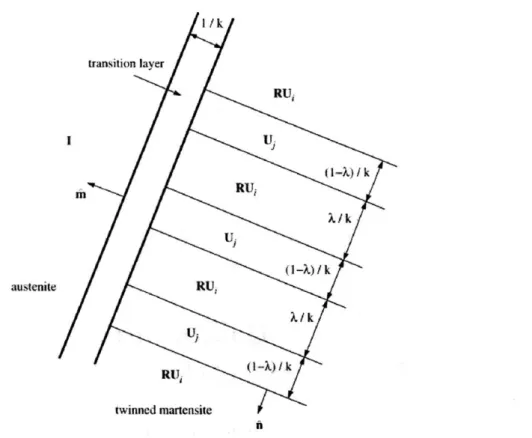
I /k transition layer RU, 1 Ui (1-.X) /k RUj X/k. austenite RU, U (1-X/k Itu twinned martensiteFigure 2-1: Austenite-twinned martensite microstructure: RjgU, and U
3represent
variant pairs that satisfy the kinematics compatibility equation [281
From an energy point of view, the geometrically nonlinear theory of martensitic
transformation states that a crystal of an SMA minimizes its overall energy by phase
twinning and its unique microstructure arises as a result of energy minimization
and strain compatibility[51. Twinning is a deformation in SMAs where two variants of martensite coexist. Schematically, phase twinning appears in SMAs as parallel bands alternately containing different variants of martensite, as shown in Figure 2-1.
The topology of the twinning structure plays a crucial role in macroscopic material properties. In the micromechanical constitutive model based on the geometrically nonlinear theory, the strain-energy minimizers appear in fine structures involving austenite and twinned martensite and are in essence rank-one tensors representing discontinuities in the deformation gradient. Those rank-one tensors are defined as the transformation tensors and take the form of:
So = bo 9 mo (2.8)
where bo is the vector denoting the transformation direction scaled by transformation strain and mo is the unit normal vector to the habit plane. A potential transformation system is defined by a set of {bi, m'} which contains sufficient information on the orientation of a compatible austenite-martensite interface[4, 51. As mentioned earlier, an important conclusion from the geometrically nonlinear theory of martensitic trans-formation is that transtrans-formation tensors So only depend on the crystal structures and lattice parameters of the austenite and martensite phases in a single crystal, therefore a complete set of transformation tensors can be calculated for a certain type of SMA.
Theoretically, the martensitic transformation in a NiTi single-crystal can appear in as many as 192 transformation systems, yet only a subset of 24 transformation systems are observed in experiments [16, 561. The components of the 24 transforma-tion systems {mi, b'} with respect to an orthonormal basis associated with the cubic austenite lattice in a NiTi are shown in Table 2.1 [2]. Anand and Gurtin have shown that the superelastic curves predicted using 24 systems are qualitatively similar to those using a complete set of 192 systems
121.
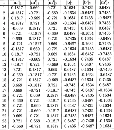
Similar calculations are carried out for Cu-based alloys and 24 transformation system are distinguished for CuZnAl SMAsas shown in Table 2.2 [27, 40, 451.
T
[mill [mi]2 [mi]3[b]
1 [bi]2[mi]3
Table 2.1: Variants of the transformation systems for NiTi
[16,
21 -0.8888 -0.8888 -0.8888 -0.8888 -0.8888 -0.8888 -0.8888 -0.8888 0 0.4045 0.5 -0.4045 0.2153 0.2153 -0.2153 0.5 -0.2153 0.4045 -0.50.4045 0.2153 0.21535 0.4045 -0.4045 0.4045 -0.4045 -0.2153 -0.2153 1 2 3 4 5 6 7 8 9 10 11 12 13 14 15 16 17 18 19 20 21 22 23 24 -0.4045 0.4045 0.2153 0.2153 -0.2153 -0.2153 0.4045 -0.4045 -0.8888 -0.8888 -0.8888 -0.8888 -0.8888 -0.8888 -0.8888 -0.8888 0.4045 -0.4045 0.2153 0.2153 -0.2153 -0.2153 0.4045 -0.4045 0.2153 0.2153 -0.4045 0.4045 0.4045 -0.4045 -0.2153 -0.2153 0.2153 0.2153 -0.4045 -0.4045 0.4045 -0.4045 -0.2153 -0.2153 -0.8888 -0.8888 -0.8888 -0.8888 -0.8888 -0.8888 -0.8888 -0.8888 0.0568 0.0568 0.0568 00568 00568 0.0568 0.0568 0.0568 0.0638 -0.0638 0.0991 0.0991 -0.0991 -0.0991 0.0638 -0.0638 0.0991 0.0991 0.0638 -0.0638 0.0638 -0.0638 -0.0991 -0.0991 -0.0638 0.0638 0.0991 0.0991 -0.0991 -0.0991 0.0638 -0.0638 0.0568 0.0568 0.0568 0.0568 0.0568 0.0568 0.0568 0.0568 0.0638 -0.0638 0.0991 0.0991 -0.0991 -0.0991 0.0638 -0.0638 0.0991 0.0991 -0.0638 0.0638 0.0638 -0.0638 -0.0991 -0.0991 0.0991 0.0991 -0.0638 0.0638 0.0638 -0.0638 -0.0991 -0.0991 0.0568 0.0568 0.0568 0.0568 0.0568 0.0568 0.0568 0.0568i I [mil [mi32
I
[mi]3[b]
1 [bi]2 [m']3 1 2 3 4 5 6 7 8 9 10 11 12 13 14 15 16 17 18 19 20 21 22 23 24 0.1817 -0.1817 0.1817 -0.1817 -0.669 0.721 0.669 -0.721 -0.1817 0.1817 -0.1817 0.1817 0.721 -0.669 -0.721 0.669 0.669 -0.721 -0.669 -0.721 -0.721 0.669 0.721 -0.669 0.669 -0.721 -0.669 0.721 0.1817 -0.1817 0.1817 -0.1817 0.669 -0.721 -0.669 0.721 0.1817 -0.1817 0.1817 -0.1817 -0.721 0.669 0.721 -0.669 -0.669 0.721 0.669 -0.721 0.721 -0.669 -0.721 0.669 0.721 -0.669 -0.721 0.669 -0.721 0.669 0.721 -0.669 0.669 -0.721 -0.669 0.721 -0.1817 0.1817 -0.1817 0.1817 -0.1817 0.1817 -0.1817 0.1817 0.1634 -0.1634 0.1634 -0.1634 0.7435 0.6487 -0.7435 -0.6487 -0.1634 0.1634 -0.1634 0.1634 0.6487 0.7435 -0.6487 -0.743 -0.743 -0.6487 0.7435 0.6487 -0.6487 -0.7435 0.6487 0.7435 -0.7435 -0.6487 0.7435 -0.6487 0.1634 -0.1634 0.1634 -0.1634 -0.7435 -0.6487 0.7435 0.6487 0.1634 -0.1634 0.1634 -0.1634 -0.6487 -0.7435 0.6487 0.7435 0.7435 0.6487 -0.7435 -0.6487 0.6487 0.7435 -0.6487 0.7435 0.6487 0.7435 -0.6487 0.7435 -0.6487 -0.7435 0.6487 0.7435 -0.7435 -0.6487 0.7435 0.6487 -0.1634 0.1634 -0.1634 0.1634 -0.1634 0.1634 -0.1634 0.1634slip by plasticity, the phase transformation deformation gradient FP is assumed to take a similar form to that in the crystal plasticity theory [561. The phase transformation velocity gradient LP depends on the summation of the transformation rate on all the systems through the relation:
N
LP = E b 0 m' (2.9)
where N is the total number of transformation systems taken into consideration.
2.1.3
Balance of Linear Momentum
Denote o as the Cauchy stress in the deformed body and the contact force on part
Pt in the deformed body Bt is given by:
andA (2.10)
where dA is an area element in the deformed configuration and n is the outward normal to the area element in the deformed configuration.
To derive the balance of linear momentum in the reference configuration, it is necessary to define a stress tensor in the reference configuration. Recall the Nanson's relation for the transformation of oriented area elements:
ndA = (det F)F-T nRdAR (2.11)
where dAR is an area element in the reference configuration and nR is the outward normal to the area element in the reference configuration.
We can therefore define a stress measure in the reference configuration,
JF, andA = (det F)F-TnRdAR (2.12)
through the relation:
S = (det F)oF-T = Jo.F-T (2.13)
Then the balance of linear momentum in the reference configuration yields:
SnRdAR + bdVR --
+
pos(dVRa P fP dt
(2.14)
where dVR is the volume of an element in the reference configuration, b is the body force per unit volume in the reference configuration and po is the reference density.
By applying the divergence theorem, the balance of linear momentum in the
ref-erence configuration can be expressed in local forms:
DivS + b = po' (2.15)
where Div is the divergence with figuration.
by neglecting dynamic effects
obtained as follows:
respect to the material point in the reference
con-and body forces, the equilibrium equation can be
DivS = 0 (2.16)
2.1.4
Balance of Angular Momentum
The balance of angular momentum in the reference configuration reads:
a
xSnRdAR
+p
x
bdVR=
---d
x pOPcdVRPflRjPXR-i
IF
(2.17)The major conclusion from the angular momentum in the deformed configuration is that the Cauchy stress tensor o is symmetric. By substituting Eq. 2.13 into Eq. 2.17, the balance of angular momentum can be expressed in local forms as follows:
2.1.5
Balance of Energy
In the reference configuration, define c as the internal energy per unit reference vol-ume, qO as the referential heat flux, and g as the heat generation rate per unit reference volume. The first law of thermodynamics in the reference configuration reads:
SnR - dAR~- qR.nRdAR+ (b - +g)dVR = (+--po-Eb)dVR (2.19)
aP t d R to to 21 l
Applying the divergence theorem to 2.19 leads to:
j (DivS - + S -V )dVR - DiqRdVRj+ (b '
+jR(E
-Po.
-b)dVR(2.20)
Recall the linear momentum balance (Eq. 2.15) and multiply both sides by b,
DivS - + b - = po
-dt 2 (2.21)
Substituting Eq. 2.21 into Eq. 2.20 leads to:
p(S - V - DivqR + g - )dVR = 0 (2.22)
Therefore the energy balance equation in local forms can be expressed as:
S - F - DivqR + 9 = (2.23)
2.1.6
Entropy Imbalance
In the reference configuration, define r7 as the entropy per unit reference volume. The entropy imbalance yields:
Introduce a Helmholtz free energy defined as:
= /(E', 0, ) = c - 10 (2.25)
where 0 is the absolute temperature and ( is the volume fraction of martensite, a measure of the degree of phase transformation.
By applying the divergence theorem and combining Eq. 2.7,2.6, 2.20, 2.24, the
entropy imbalance can be written as:
{Te } E { + (Ce T) - LP - 0 (2.26)
&Ee} 00
{
~O(ee.P
(
where a new stress measure, the elastic Piola-Kirchoff stress is introduced: Te
JFe-1 e--T
2.1.7
Free Energy
Following the formulation proposed in Anand and Gurtin (2003) [21, the free energy per unit reference volume V) can be decoupled into three terms: the strain energy Vy, the energy of phase transformation 7PP, and the thermal energy 7P.
(Ee
0, ) - V5(E6, 0) + VP( , 0) + 0 (0) (2.27)The strain energy is taken to be a quadratic functional in Ee: 1
0(E',
0)
= -E' -CE6 (2.28)2 where C is the fourth-order elasticity tensor.
The energy of phase transformation is given by:
where OT - (m, + 0as) is the phase equilibrium temperature, AT is the latent heat
of phase transformation at OT. The thermal energy is given by:
( , 0) = c(O - 00) - cO In --0
0 (2.30)
where c is the constant specific heat, and 0 is the reference temperature.
Combining the above equations, the entropy imbalance can be rewritten in the following form:
{Te D.e} - 7 + Q)O + (CeT) -LP
-qO- .VO ;> 0 -0 O
2.1.8
Constitutive Equation for Elastic Stress
In Eq. 2.31, consider the case where LP = 0, 70 = 0, 9 = 0. Guided by the Coleman-Noll procedure, to satisfy the inequality, the following relation must hold:
Te = E (2.32)
We arrive at the constitutive equation for the elastic stress:
MEe (2.33)
The fourth-order stiffness matrix C(s) depends on the volume fraction of martensite
and the elastic modulus Cijkl is calculated using the rule of mixtures:
CijkI = XCxi + (1 - )Cijkl (2.34)
where C' is the elastic modulus for martensite and C is the elastic modulus for
austenite.
The elastic Piola-Kirchhoff stress T' is work-conjugate to the elastic strain E'.


![Figure 2-6: Comparison of the stress-strain response at different temperatures with the rate-dependent model in [2]](https://thumb-eu.123doks.com/thumbv2/123doknet/14435929.516008/55.917.262.628.574.852/figure-comparison-stress-strain-response-different-temperatures-dependent.webp)