HAL Id: hal-02053240
https://hal.archives-ouvertes.fr/hal-02053240
Submitted on 1 Mar 2019
HAL is a multi-disciplinary open access
archive for the deposit and dissemination of
sci-entific research documents, whether they are
pub-lished or not. The documents may come from
teaching and research institutions in France or
abroad, or from public or private research centers.
L’archive ouverte pluridisciplinaire HAL, est
destinée au dépôt et à la diffusion de documents
scientifiques de niveau recherche, publiés ou non,
émanant des établissements d’enseignement et de
recherche français ou étrangers, des laboratoires
publics ou privés.
K/Ka-Band Transmitarray Antennas Based on
Polarization Twisted Unit-Cells
Kien Pham, Ronan Sauleau, Erwan Fourn, Fatimata Diaby, Antonio
Clemente, Laurent Dussopt
To cite this version:
Kien Pham, Ronan Sauleau, Erwan Fourn, Fatimata Diaby, Antonio Clemente, et al.. K/Ka-Band
Transmitarray Antennas Based on Polarization Twisted Unit-Cells. 12th European Conference on
Antennas and Propagation (EuCAP), Apr 2018, Londres, United Kingdom. �10.1049/cp.2018.0995�.
�hal-02053240�
K/Ka-Band Transmitarray Antennas Based on
Polarization Twisted Unit-Cells
Kien Pham
*+1, Ronan Sauleau
*+, Erwan Fourn
*✝, Fatimata Diaby
#§, Antonio Clemente
#§, Laurent Dussopt
#§* IETR, UMR CNRS 6164, France
+ University of Rennes 1, 35042 Rennes Cedex, France ✝ INSA de Rennes, CS70839, 35708 Rennes Cedex, France # CEA, LETI, MINATEC Campus, 38054 Grenoble, France § University of Grenoble-Alpes, 38000 Grenoble, France
1 [email protected] Abstract—This paper presents a dual-band dual linearly
polarized transmitarray unit-cell designed for satellite communications in K/Ka-band (down link: 18.8-21 GHz; up-link: 27.5-31 GHz). Single-band unit-cells with linear orthogonal polarizations are firstly designed separately in each band. Their frequency response shows a −10-dB impedance bandwidth of more than 9% around 29 GHz and 19.5 GHz, with a 180° phase-shift in both bands. Those unit-cells are optimized with the same periodicity (6 mm, which is equivalent to 0.58-wavelength in free space at 29 GHz). The extremely low mutual coupling between these unit-cells allows designing a dual-band transmitarray by simply interleaving two single-band sub-arrays operating in the up- and down-links. Single- and dual-band transmitarray antennas are designed to validate the proposed concepts and demonstrate that they exhibit similar radiation performance in both bands, thereby proving the
relevance of the proposed interleaving technique.
Experimentally, the maximum gain obtained at 29 GHz and 19.5 GHz for a beam pointing at boresight reaches 26 dBi and 23 dBi respectively, with a side lobe level better than -20 dB at both frequencies.
Index Terms— Transmitarray antenna, dual-band, Ka-band, discrete lens antenna.
I. INTRODUCTION
Transmitarrays are promising solutions for many applications at millimeter wave frequencies [1]-[3]. The working principle of a transmitarray consists in collimating the incident wave from a feed horn into a desired direction. A transmitarray can be decomposed into three main building blocks, namely a receiving layer to collect the incident wave from the feed horn, a transmitting layer to radiate the wave to free space, and a phase-shifter used to compensate the different path lengths from the feed horn to the unit-cells (see Fig.1). To implement successfully a transmitarray, the unit-cell must ideally offer total transmission in the band of interest with capability to control the transmission phase.
Various technologies of multi-band antenna arrays have been proposed over the last decades. Like reflectarray antennas (RAs) [4], transmitarray antennas (TAs) are in this flow. Some preliminary demonstrations at the unit-cell level have been proposed in X-, K- and Ka-bands [5]-[7]. A dual-band unit-cell based on MMIC technology is introduced in [5] with up- and down-link patches arranged in aperiodic array.
Moreover, several passive dual-band unit-cells operating in circular polarization and based on rotation technique to control the transmission phase have been proposed. As reported in [6], five identical layers of rotated cut-rings printed on four 0.784-mm–thick RT 5880 substrates are combined to obtain 360° phase variation at each frequency band. In [7], a combination of a cut-ring with a thin microstrip patch is proposed to vary simultaneously the phase-shift at two frequencies by rotation technique. A dual-band metal-only transmitarray operating in X-band with high efficiency (37.2 % at 11 GHz and 34 % at 12.5 GHz) and dual-polarization for two close bands has been presented in [8]. However the layout is not optimal in each band because the average frequency of 11 GHz and 12.5 GHz is used in the design. Better performance and independency of each frequency are proposed in [9] at Ku-band. Although high efficiency is obtained, the achieved bandwidth is quite narrow and no steering capability is studied due to large periodicity of unit-cell (0.90 at 18 GHz). Recently, a dual-band Satcom
transmitarray at Ka-band has been presented in [10] with complex stack-up configuration (6 substrates and 7 metallic layers) and the unit-cell exhibits dependent phase variation between two frequencies (20 GHz and 30 GHz).
Fig. 1. Geometry of a transmitarray with its unit-cell.
z y x Horn Focal Receiving
To overcome the above-mentioned limitations, we introduce here a simple and easy-to-design dual-band unit-cell operating in the 18.8 - 21 GHz band (down link) and 27.5 - 31 GHz band (up-link) for satellite communications in K/Ka band [11]. We will show that transmission phase of the unit-cell can be varied independently in each frequency band without interfering the frequency response in the other band. The unit-cell architecture is very simple and is based on a three metal layer design. The frequency responses of the proposed unit-cell are discussed in Section II. Then, we compare in Section III the radiation performance of two sets of TAs, one dual-band TA built from the proposed dual-band unit-cell, and two single-band TAs operating either in the down-link band or in the up-link one. Finally, conclusions are drawn in Section IV.
II. NUMERICAL STUDY OF UNIT-CELLS
The proposed unit-cell relies on two design principles: polarization twisting and frequency scalability. Its dimensions are optimized separately in each frequency band using Floquet port and periodic boundary conditions in Ansys HFSS version 15. All frequency responses have been computed assuming a Floquet illumination under normal incidence.
Fig. 2. 3D view of the single-band (SB) unit-cell.
Fig. 3. 3D view of the dual-band (DB) unit-cell. The up-link and down-link patches are shown in blue and red respectively. Note that the lattice size is the same in both bands.
A. Designs and Characteristics
Fig. 2 represents the 3D view of the single-band (SB) unit-cell in a periodicity of 6 mm. It is made of narrow microstrip
patches printed on the receiving and transmitting layers on two identical dielectric substrates (Rogers Duroid RT6002, hs
= 0.762 mm, εr = 2.94, and tanδ = 0.0012). Both patches are
connected by a metalized via hole (diameter of 200 µm). A circular aperture with a diameter of 800 µm is used to isolate this via hole from the ground plane. A thin film (Arlon CuCLAD 6700, εr = 2.35, and tanδ = 0.0025) is used to bond
the two substrates.
This unit-cell operates in linear polarization. The metallized via connects the receiving and transmitting patches; it is located at the center of the unit-cell and divides each patch into two unbalanced parts. Thanks to this via working as a reference point for the electric field, the polarization can be changed either at the receiving or transmitting layer by rotation of the patches. In the current work, the receiving layer is rotated by 180° so that the unit-cell exhibits a 1-bit transmission phase quantization (180° phase resolution), whereas the transmitting layer is rotated by 90° to rotate the field polarization. Consequently, contribution of spill-over radiation on the co-polarization pattern is significantly reduced. The SB unit-cell is able to operate either in the up- or down-link bands by scaling the dimensions of the radiating patches. Their length and width equal 3 mm/4.65 mm and 0.5mm/0.65mm for the up-/down links respectively.
(a)
(b)
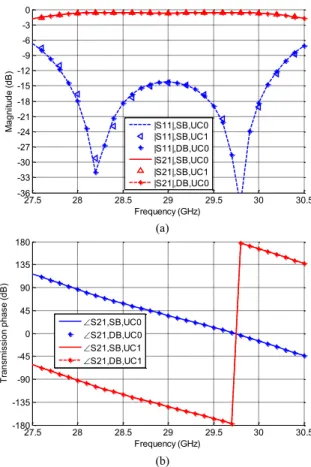
Fig. 4. Frequency responses of the single-band (SB) and dual-band (DB) unit-cells in the up-link band. (a) Magnitude of reflection and transmission coefficients for the 0°/180°-phase states of the unit-cell (UC0/UC1). (b) Transmission phase for the 0°/180°-phase states of the unit-cells (UC0/UC1).
27.5 28 28.5 29 29.5 30 30.5 -36 -33 -30 -27 -24 -21 -18 -15 -12 -9 -6 -3 0 Frequency (GHz) M a g n itu d e ( d B ) |S11|,SB,UC0 |S11|,SB,UC1 |S11|,DB,UC0 |S21|,SB,UC0 |S21|,SB,UC1 |S21|,DB,UC0 27.5 28 28.5 29 29.5 30 30.5 -180 -135 -90 -45 0 45 90 135 180 Frequency (GHz) T ra n sm issi o n p h a se ( d B ) S21,SB,UC0 S21,DB,UC0 S21,SB,UC1 S21,DB,UC1
Fig. 3 represents the 3D view of the dual-band (DB) unit-cell with a square periodicity of 6 mm. It is a combination of the interleaved SB unit-cells operating individually in the up-link and down-up-link. In this figure, the up-up-link unit-cell is plotted in blue and located at the center, while the down-link unit-cell is shown in red.
B. Frequency Responses
The frequency responses of the up-link unit-cell alone and in presence of surrounding down-link unit-cells are compared in Fig. 4. We can notice in Fig. 4(a) that the reflection and transmission coefficients in magnitude are the same for both phase states, and for the SB and DB designs. More precisely, the -10 dB impedance bandwidth spans from 27.7 GHz to 30.3 GHz (2.6 GHz or 9% around 29 GHz). The insertion loss is low over the fractional bandwidth, e.g. about 0.4 dB at 29 GHz. The superimposing of SB and DB unit-cell in transmission phase over frequency is also observed (Fig. 4b). Moreover, Fig. 4(b) also shows that the unit-cell exhibits a 180° phase shift over the whole bandwidth with a maximum phase variation of +/-2°. Finally, similar conclusions can be drawn for the down-link band (results not shown here for brevity), with a -10dB reflection bandwidth of 1.8 GHz (from 18.8 GHz to 20.6 GHz), equivalent to 9.2% around 19.5 GHz.
Fig. 5. Simulation configuration for SB and DB TAs using in HFSS.FE-BI.
These very attractive features lead to a simplified design procedure because only one phase state needs to be considered, e.g. 0°-state (UC0). In addition, as the frequency responses are exactly the same for the SB and DB designs, this implies that mutual coupling between up- and down-link unit-cells is extremely low. Therefore, the DB transmitarray can be designed easily first by designing separately two SB transmitarrays, and second by interleaving them, as done at the unit-cell level (Fig. 3).
III. DUAL-BAND TRANSMITARRAY ANTENNAS BASED ON
POLARIZATION TWISTED UNIT-CELLS
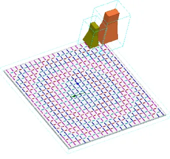
Based on the DB unit-cell described in Section II, we design here a DB TA, and compare its performance to those of two SB TAs (one operating in the up-link, and one in the down-link). The DB TA works in dual-linear polarization, one polarization for each band, e.g. y-polarized for the up-link band and x-polarized for the down-link. It is illuminated by two separate pyramidal feed horns. In the DB scenario, two feed horns are placed at 79 mm (focal distance) away from the radiating panel. The up- and down-link horns (in yellow and orange in Fig. 5, respectively) are placed in offset positions (+/- 10 mm from z-axis) in the xz-plane.
The TAs have been simulated using hybrid finite element boundary integral method (FE-BI) of HFSS as illustrated in Fig. 5 for the DB TA. They radiate a pencil beam at broadside.
A. Transmitarray Designs
The up- and down-link transmitarrays layouts are represented in Fig. 6. The up-link array is made of 400 unit-cells arranged in 20-by-20 square matrix while the down-link one consists of a 21-by-21 matrix (441 unit-cells).
(a) (b)
Fig. 6. Antenna layouts (phase states of the unit-cells, in deg.) for a beam pointing at broadside computed at 29 GHz for the up-link (a), and at 19.5 GHz for down-link (b).
The layouts of single- and dual-band TAs have been generated using our in-house hybrid analysis tool [2]-[3], [12]. Thanks to the very low mutual coupling between the SB unit-cells, the TA design procedure first starts with the definition of the single-band layouts for the up- and down links separately. Then, the DB layout is simply obtained by interleaving both SB layouts.
B. Radiation Performance
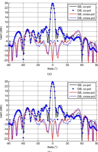
The radiation patterns simulated at the center frequencies of each band (29 GHz and 19.5 GHz for the up- and down-link bands, respectively) are represented in Figs. 7 and 8.
The co-polarization and cross-polarization components at 29 GHz are almost superimposed in both principal planes (E- and H- planes) for single-band (SB) and dual-band (DB) TA (see Fig. 7). The side lobe level remains below -20 dB while the cross-polarization level is kept under -24 dB for all elevation angles. Similar conclusions can be drawn at 19.5 GHz (Fig. 8).
These results clearly demonstrate independency between both bands, and thus validate the interleaving concept with polarization twisted unit-cells. This concept has been also validated numerically for antenna beams pointing in offset directions (results not shown for brevity purposes).
(a)
(b)
Fig. 7. Co- and cross-polarization components computed in E-plane (a) and H- plane (b) for single-band (SB) and dual-band (DB) transmitarray antennas at 29 GHz.
IV. CONCLUSION
Dual-band unit-cells and transmitarray antennas have been proposed for applications in K/Ka-bands. The proposed concept consists in interleaving two very weakly coupled single-band transmitarrays sharing the same radiating aperture and operating in linear orthogonal polarization. Comparison between the single-band and dual-band designs confirms the relevance of the proposed designs. Thanks to this technique, the design procedure is simplified significantly since the layout is optimized individually for each band.
ACKNOWLEDGMENT
This works is supported by The French National Research Agency (ANR) in the project named TRANSMIL (TRANSmitarray antenna at MILlimeter-wave) under Grant ANR-14-CE28-0023.
(a)
(b)
Fig. 8. Co- and cross-polarization components computed in E-plane (a) and H- plane (b) for single-band (SB) and dual-band (DB) transmitarray antennas at 19.5 GHz.
REFERENCES
[1] A. Abbaspour-Tamijani, K. Saranbandi, and G. M. Rebeiz “A millimeter-wave bandpass filter-lens array,” IET Microw. Antennas Propag., vol. 1, no. 2, pp. 388–395, Apr. 2007.
[2] H. Kaouach, L. Dussopt, J. Lantéri, R. Sauleau, and T. Koleck, “Wideband low-loss linear and circular polarization transmitarray in V-band,” IEEE Trans. Antennas Propag., vol. 59, no. 7, pp. 2513– 2523, Jul. 2011.
[3] L. Di Palma, A. Clemente, L. Dussopt, R. Sauleau, P. Potier, and Ph. Pouliguen, “Circularly-polarized transmitarray with sequential rotation in Ka-band,” IEEE Trans. Antennas Propag., vol. 63, no. 11, pp. 5118– 5124, Nov. 2015.
[4] L. Guo, P. Tan, and T. Chio, “Single-layered broadband dual-band reflectarray with linear orthogonal polarizations,” IEEE Trans. Antennas Propag., vol. 64, no. 9, pp. 4064–4068, Sep. 2016. [5] T. Chaloun, C. Hillebrand, C. Waldschmidt, and W. Menzel, “Active
transmitarray submodule for K/Ka band satcom applications,” in Proc. IEEE GeMiC, Nürnberg, Germany, pp. 198–201, Mar. 16-18, 2015. [6] H. Hasani, J. S. Silva, J. R. Mosig, and M. García-Vigueras,
“Dual-band 20/30 GHz circularly polarized transmitarray for SOTM applications,” 10th European Conf. Antennas and Propagation, Davos,
Switzerland, Apr. 10-15, 2016.
[7] P. Naseri, R. Mirzavand, and P. Mousavi, “Dual-band circularly polarized transmit-array unit-cell at X and K bands,” 10th European
Conf. Antennas and Propagation, Davos, Switzerland, Apr. 10-15, 2016.
[8] M. O. Bagheri, H. R. Hassani, and B. Rahmati, “Dual-band, dual-polarised metallic slot transmitarray antenna,” IET Microw. Antennas Propag., vol. 11, no. 3, pp. 402-409, 2017.
-90 -60 -30 0 30 60 90 -22 -18 -14 -10 -6 -2 2 6 10 14 18 22 26 theta (°) G a in ( d B i) SB, co-pol DB, co-pol SB, cross-pol DB, cross-pol -90 -60 -30 0 30 60 90 -22 -18 -14 -10 -6 -2 2 6 10 14 18 22 26 theta (°) G a in ( d B i) SB, co-pol DB, co-pol SB, cross-pol DB, cross-pol -90 -60 -30 0 30 60 90 -22 -19 -16 -13 -10 -7 -4 -1 2 5 8 11 14 17 20 23 theta (°) G ai n (d B i) SB, co-pol DB, co-pol SB, cross-pol DB, cross-pol -90 -60 -30 0 30 60 90 -22 -19 -16 -13 -10 -7 -4 -1 2 5 8 11 14 17 20 23 theta (°) G ai n (d B i) SB, co-pol DB, co-pol SB, cross-pol DB, cross-pol
[9] R. Y. Wu, Y. B. Li, W. Wu, C. B. Shi, and T. J. Cui, “High-gain dual-band transmitarray,” IEEE Trans. Antennas Propag., vol. 65, no. 17, pp. 3481-3488, 2017.
[10] S. A. Matos, E. B. Lima, J. S. Silva, J. R. Costa, C. A. Fernades, N. J. G Fonseca, and J. R. Mosig “High gain dual-band beam-steering transmit array for satcom terminals at Ka-band,” IEEE Trans. Antennas Propag., vol. 65, no. 7, pp. 3528-3539,Jul. 2017.
[11] R. Pearson, “Next generation mobile SATCOM terminal antennas for a transformed world,” 5th European Conf. Antennas and Propagation,
Rome, Italy, Mar. 11-15, 2011.
[12] K. Pham, N. T. Nguyen, A. Clemente, L. Di Palma, L. Le Coq, L. Dussopt, and R. Sauleau, “Design of wideband dual linearly-polarized transmitarray antennas,” IEEE Trans. Antennas Propag., vol. 64, no. 5, pp. 2022–2026, May 2016.