HAL Id: hal-01095667
https://hal.inria.fr/hal-01095667
Submitted on 16 Dec 2014
HAL is a multi-disciplinary open access
archive for the deposit and dissemination of
sci-entific research documents, whether they are
pub-lished or not. The documents may come from
teaching and research institutions in France or
abroad, or from public or private research centers.
L’archive ouverte pluridisciplinaire HAL, est
destinée au dépôt et à la diffusion de documents
scientifiques de niveau recherche, publiés ou non,
émanant des établissements d’enseignement et de
recherche français ou étrangers, des laboratoires
publics ou privés.
MobileRGBD, An Open Benchmark Corpus for mobile
RGB-D Related Algorithms
Dominique Vaufreydaz, Amaury Nègre
To cite this version:
Dominique Vaufreydaz, Amaury Nègre. MobileRGBD, An Open Benchmark Corpus for mobile
RGB-D Related Algorithms. 13th International Conference on Control, Automation, Robotics and Vision,
Dec 2014, Singapour, Singapore. �hal-01095667�
MobileRGBD, An Open Benchmark Corpus for
mobile RGB-D Related Algorithms
Dominique Vaufreydaz, Amaury N`egre
Prima - Inria, LIG, Univ. de Grenoble, CNRS Zirst Montbonnot, 655 avenue de l’Europe
38334 Saint Ismier cedex - France
Email: [email protected], [email protected]
Abstract—Since the commercialization of low cost RGB-D sensors, like the Kinect, more and more indoor robots have been equipped with this kind of sensors to perform tasks as people tracking or gesture recognition. Nevertheless, as far as we know from the literature, studies do not consider the limits of the sensors in term of motion speed, position of the sensor on the robot, etc. In this work, we propose to provide a corpus dedicated to low level RGB-D algorithms benchmarking. Originality of our approach is the use of dummies in order to play static users in the environment. This idea let us vary other variables that can impact algorithm performance: linear/angular speed of the robot, trajectory of the robot, RGB-D sensor height and vertical angle of view, number and relative position of dummies and furniture position. This paper first describes the experimental platform used to perform the acquisitions and the environment setup required to reproduce the dataset. Then, a precise description of all available data is given. We will see that, as this corpus contains a lot of configurations, it will allow researchers to investigate how these variables impact the results of their algorithms.
I. INTRODUCTION
Body shape, gesture, body language detection and evalua-tion are not new areas of research. Several years ago, one can use computer vision algorithms in order to detect pedestrians, bodies or objects from a video stream. Later on, researchers have used Time-Of-Flight (TOF) cameras in order to achieve this task but these devices are expensive. Nowadays, many researches on this topic are done using Kinect of other RGB-D sensors [1].
Many robotic researches, especially but not only in re-searches about companion robot, are using RGB-D sensors like the Kinect for many tasks: 3D SLAM, people tracking and skeleton tracking, gesture recognition, body pose estimation, engagement toward a robot or for elderly at home, detecting falls or searching for a fallen person ([2], [3], [4], [5], [6], [7], [8]). We totally agree with [9], benchmarking is one pillar of research in these domains: how can one states that an algorithm performs better without a common reference? For instance, in [10], a fall detection system is depicted with an interesting approach and good performances but description of the train/test corpus is not detailed enough. Thus, this corpus is not reproducible and results not comparable to other approaches.
RGB-D related algorithms are difficult to benchmark as there is no reference corpora with ground truth labels for every task or/and condition. Focusing on all body related tasks, it is even more difficult to record data. Labeling depth data with
skeletons is not an easy task and recording many times people enhanced variability but increase difficulty of the labeling task. Several corpora using RGB-D are available for many tasks. One can find corpora for language signing [11] or mental state computation [12] for instance. [13] proposed a Human activities dataset for ICPR 2012 human activities recognition and localization competition. This dataset exposes humans in everyday-life tasks recording using the Kinect sensors. Labeling is done on human activities, i.e. at a high level of annotation. One cannot state performances of skeleton or face detection using this corpus even these features can be used for the activity recognition. Few corpora are available on with a mobile robot equipped with an RGB-D sensor. In [2], the RGB-D data are dedicated to SLAM. Mobile paths were done using a man handled and a robot mounted Kinect device. For the robot recordings, linear speed is from 0.1 to 0.23 m.s−1 and angular speed is around 12 deg.s−1. Ground truth labels are provided by a calibrated motion capture system, but no body features are provided. One can find a more correlated approach in [3]. The authors use a Kinect mounted on a cleaning robot in order to evaluate upper body skeleton tracking. People were asked to play predefined gestures in front of the robot while it is rotating. In this study, we have no information about the robot or its angular speed. Moreover, variability in this case is not only due to the speed of the robot but also to human gestures. Between two records, humans’ moves are different, thus can introduce variability on detection algorithms. These artifacts can lead to different results for several speeds, not depending on the speed itself but on external variables.
In this paper, we first present our design path and objectives in section II. Section III depicts our experimental environment, i.e. our experimentation room and robotic platform. We give clues about control of the robot in order to make reproducible recording trajectories and RGB-D sensor vertical angle cali-bration. Gathered data using the Kinect 2 device mounted and the robot sensors are detailed in section IV.
II. DESIGN PATH AND OBJECTIVES
From our experience of using RGB-D sensors on mo-bile robot, we know it could be difficult to isolate which changes/variables impact performance of a specific algorithm: is it due to the robot speed, the number of persons at the same time, their relative position, etc. Sometimes, we even improve performance by changing position or field of view of
the mounted RGB-D sensor on the robot. Looking at design of some mobile platforms like the Hobbit [14], the turtlebot1
[15], a tobotic Wheelchair [16] or our version of the Kompa¨ı [7], positions of using mounted RGB-D sensor differ. Most of the time, it was parallel to the floor plane. These choices are often driven by human, technical or design considerations without evaluating impact on the algorithms. From all the reasons above, we can extract a set of variables that we want to address in our corpus:
• linear and angular robot speed;
• number and position of persons in the environment; • furniture placement and body occlusions;
• height and vertical field of view of the RGB-D sensor, i.e. looking down or up at several positions;
• body orientation toward the sensor;
We thought to reverse the corpus recording paradigm. Our goal is to facilitate ground truth annotation and reproducibility of records among speed, trajectory and environmental varia-tions. As we want to get rid of unpredictable human moves, in our benchmark corpus, we use dummies (see 2). Interest of dummies resides in the fact that they do not move between two recordings. It is possible to record the same robot move in order to evaluate performance of detection algorithms varying speed.
Our goal is to provide a benchmark corpus for “low level” RGB-D algorithm family like 3D-SLAM, body/skeleton tracking or face tracking using a mobile robot. Using this open corpus, researchers can find a way to answer several questions: • what is the algorithm performance in multiples
condi-tions?
• on a mobile robot, what is the maximum linear/angular speed supported by the algorithm?
• which variables impact the algorithm?
• evaluate suitable height/angle of the mounted RGB-D sensor to reach goals: monitoring everyday live is different from searching fallen persons on the floor; • finally, what is the performance on an algorithm with
regards to others?
III. EXPERIMENTAL SETUP
A. Room description
The experimental room is a flexible space designed to be representative of a home-like environment. It has an ’L’ shape with a kitchen place with a sink, a diner and a lounge space. The size of the room is 6x8 m. A view of the kitchen space is shown on the fig. 2. Except the sink, furniture can be moved ad libitumto reflect experimental needs.
In our setup, dummies are in the kitchen. The robot moves from the dining room toward the dummies. Some furniture is available to create different setups and placed to make
1http://www.turtlebot.com/
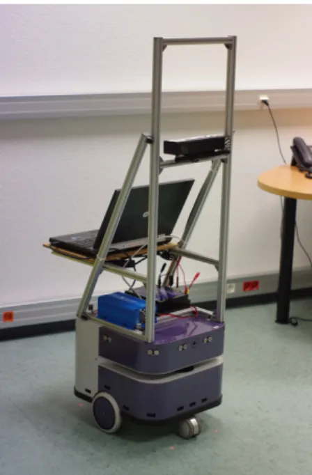
Fig. 1. Robotic platform used for recording: a Robulab10 mobile robot from the Robosoft compagny. It is equipped with a laser ranger finder, a Kinect 2.0 and a laptop computer.
Fig. 2. View of the experimental room. The room is designed to simulate a real living apartment. Some augmented reality tags have been placed around the two dummies.
some occlusions: sofa, table and chairs. Augmented reality tags are on the walls and let us have more 3D information that information gathered from the robot laser range finder (see III-B).
B. Platform description
Our recording platform is depicted on fig 1. For the robotic part, we used a Robulab102 mobile platform with 2 lateral
propulsive and 2 castor wheels. Each propulsive wheel can been control independently. The Robulab10 is equipped with a laser range finder, 8 ultrasound and 16 infrared telemeters. On its top, we mounted a flexible structure with a Kinect 2. This structure lets us change manually the height of the sensor 2The Robulab10 platform is sold by the Robosoft compagny http://www.
and, using servomotor, one can programmatically modify the vertical angle of view. Last, a laptop is used for control and record facilities.
C. Localization and trajectory following
The robot trajectory repeatability is one of the key aspects to compare different configurations. In this sense, an abso-lute accurate robot localization is required. To provide such localization a map of the room is exploited in combination of the laser sensor data. The chosen solution consists on a variant of Iterative Closest Point algorithm [17] based on a point-to-line measure to compute the transformation that best matches the laser point cloud to the walls and static furniture (see Fig. 3). This localization is performed in real time and we experimentally measured a centimeter accuracy.
Fig. 3. Robot localization, an ICP point-to-line method is used to compute the transformation that minimize the distance between laser points and map.
Once the robot localization is known, we implement a rectilinear trajectory following algorithm. The robot command is decomposed on a linear speed and an angular speed. To control the angular speed, we first compute a control point in front of the robot, located in the linear trajectory (see Fig. 4). Then we calculate the error (ψ) as the angle between the robot direction and the control point direction. This error is injected to a PID controller to obtain a filtered angular speed command. For the linear speed control, we simply use a trapezoidal speed profile, decomposed in three steps to avoid hard acceleration. In the first step, the speed v increased linearly with the time t:
v(t) = a · t2
In the second step, the speed is constant at requested value. Last, the robot decelerates progressively, the speed decrease is computed using the square root of the distance to the goal d:
v =√2 · a · d
D. Sensor height and tilt mechanism
Height of the RGB-D device, i.e. its basement position relatively to the floor, can be modified manually. This posi-tion varies from 48 to 128 cm. The sensors are 4 cm over
Fig. 4. Trajectory servoing.
the basement, thus, the recording positions of the mounted Kinect 2 are from 52 to 132 cm with a 10 cm step. In our hardware structure, we added a servomotor to rotate vertically the Kinect. Behind this idea, we want to investigate if it is more suitable to have a lower Kinect looking up, a central or a higher one looking straight or down on a future robot. This setup also deserves to improve search algorithm for a fallen person, i.e. we must have a floor view using the Kinect.
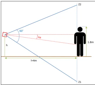
Fig. 5. From the height of the RGB-D sensor (h), computation of the percentage of a 1.8m person in the field of view at l=4m for a specific angle ka. Z1and Z2 are respectively lowest and highest visible points at a 4m distance. One can find an example in table I.
Step of the servomotor is (360/4096)◦< 0.1◦. To calibrate it for our specific angle set, we first extracted from the depth data the normalized coefficients of the floor plane x, y, z and w the actual height of the sensors. For each servomotor position, we computed the Kinect angle (ka) in regards to the floor:
ka = atan2(F loorP lane.z, F loorP lane.y)
Obviously, recording angles depend on the height of the RGB-D sensor. On lower position, we did not record floor view and on higher position we did not record ceil view. As the max depth value is 4.5m, We decided to record every angle that permits at 4m to see at least 50% of a 1.80m body (see Fig 5). Using ka, we computed Z1 and Z2, respectively the lowest and highest visible points at a 4m distance. The percentage of visible body is then computed directly:
-60 -40 -20 0 20 40 60 0.4 0.6 0.8 1 1.2 1.4 0 0.2 0.4 0.6 0.8 1 Ratio Kinect angle (°) Kinect height (m) Ratio 0 0.2 0.4 0.6 0.8 1
Fig. 6. Varying the height of the sensor (h in fig. 5), compute percentage of a 1.80m body in the field of view at l=4m regards to a set of angles. For each height, retained recording angle are over 50%.
Fig 6, shows all body percentage values varying h. In the table I, one can find example using the lowest sensor height (h=0.52m). In this case, we recorded using angles from −20◦ to 35◦ using a 5◦ step. For the highest position (h=1.32m), retained angles are from from −35◦ to 20◦ with the same step.
IV. CORPUS ACQUISITION
A. Scenarios
Among variables, our scenarios first must handle dummies and furniture placements within the experimental space. Dum-mies are set by one or two in several positions: in front of the rear wall, in front of the sink, sited on the sofa or behind a table to create partial body occlusion for instance (see fig. 2). Other variables for our recording scenarios are recording speed and path. On fig. 7, one can see some example of recording trajectories (more trajectories are tackled in the corpus). Each blue arrow represents a robot trajectory recorded at several speeds forward and backward. We do strait trajectories ending far or closer to the rear wall. Curved paths and pure rotations are also used. Last, as seen on fig. 7, trajectory at 45◦ are followed by our robot.
For each trajectory, several records are made setting the linear speed from 0.1 to 1.1 m.s−1 with a 0.1 step. The maximum linear speed of the propulsive wheels 1.3 m.s−1, thus we must limit the maximal speed in order to be able to make the robot turn. For the pure rotations, angular speed is set from 0.1 rad.s−1 to 2 rad.s−1.
We envision to record more complex paths among a full home-like setup and in some corridors.
B. Data acquisition
This project started with the release of the new Kinect 2 sensor3. At the recording time, OpenNI under Linux 4 does not handle correctly this new device. Thus, we choose to use the sensor under the Windows Kinect SDK. We recorded
3We are members of the Kinect 2 for Windows beta test program. 4http://www.openni.org/?
Fig. 7. Exemples of robot moves while recording. The dummies (green rectangles) and furniture (red lines) setup is the one presented on figure 2. Blue arrows represent robot trajectories.
synchronously all available streams from our mobile platform (see section III-B). Features are all robot centered.
The Kinect sensor exposes several data streams. Some of them are shown in fig. 1. Some difficulties raised when real-time acquisition of all the sensors equipping the Kinect is done. Asking for multiple streams at the same time can lead to variations on streams frame rate. For instance, when a skeleton is detected, the RGB frame rate slightly decreases. Optimization on the acquisition code was made in order to record all streams without information loss. An equal care was made to gather data from the Robulab10 platform.
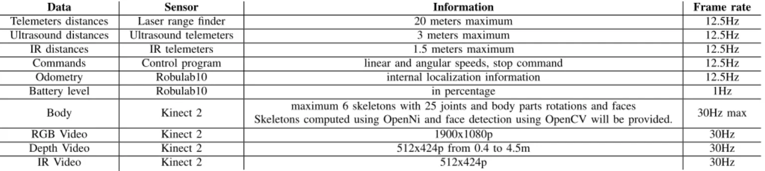
Finally, we record at the highest possible frame rate several robot centered information. RGB, depth and infrared streams, detected skeletons are gathered from the Kinect 2. From the robot, laser range finder, acoustic and infrared telemeters, battery level, wheel odometry, current linear and angular speeds are monitored. All information is stored in uncom-pressed format in order to remove coding/decoding artifacts on video streams for instance. Each frame/event is tagged using timestamps in ms from epoch time5 and can be synchronized for viewing or processing. The data recorded to build the corpus are summarized in the table II.
1) Videos streams: The resolution of the RGB image is of 1920 × 1080 pixels at 30 frames per second. The RGB sensor has a 70◦ horizontal and 60◦ vertical field of view wide-angle lens. Data are stored in 2 files. The first one is a binary raw concatenation of all YUV received images. The second one is a text file containing all timestamps associated with video frames. A compressed video file is provided for human needs. Portable C++ source code is also provided for reading frames using OpenCV6.
2) Depth and Infrared streams: In the Kinect 2, the depth stream is a real Time-Of-Light (TOF) approach whereas previ-ous Kinect versions that use structured light. It is also an active IR device, thus there is an IR video stream associated to the depth information. The depth range of the Kinect is limited from 0.4 meter to 4.5 meters. The depth is measured in meters from the camera along the Z axis, X and Y axis are in pixel coordinates. The resolution of the depth and IR images is of 512 × 424 pixels. The frame rate is at maximum 30 frames per second. As for the RGB streams, IR and depth streams are both stored using a binary raw file and associated timestamps in a separate text file.
5The timestamps are expressed in time since 1stof January, 1970. 6http://http://opencv.org/
Angle in degree -25 -20 -15 -10 -5 0 5 10 15 20 25 30 35 40
Z1 -5.19 -4.25 -3.48 -2.84 -2.28 -1.79 -1.35 -0.94 -0.55 -0.19 0.17 0.52 0.87 1.23
Z2 0.87 1.23 1.59 1.98 2.39 2.83 3.32 3.88 4.52 5.29 6.23 7.45 9.10 11.51
visible % 48.33% 68.07% 88.43% 100.00% 100.00% 100.00% 100.00% 100.00% 100.00% 100.00% 90.55% 71.11% 51.67% 31.93%
TABLE I. KNOWING THE HEIGHT OF THE SENSOR(HEREh=0.52m),COMPUTATION OFZ1, Z2 (SEE FIG. 5),AND PERCENTAGE OF BODY IN THE FIELD OF VIEW FOR A SET OF ANGLES. IN BOLD,RECORDING ANGLES WITH PERCENTAGE OVER50%.
Fig. 8. Robot sensor view. At left, the laser range finder view. In the middle, the RGB stream. Last, the infrared view. The depth view (not on this figure) is aligned with the infrared one.
3) Body information: The Kinect on Windows SDK sup-ports up to 6 skeletons tracked at the same time (it used to be 2 with the previous sensor version). Each skeleton is associated to a bag of pixels from the depth image. They now contains 25 joints (20 previously) more morphologically placed within the body shape. New joints concern neck, thumbs and hand tips. 3D information about joints is enhanced by quaternions giving rotations of body parts. We also have information about face detected in the RGB stream and/or from the depth stream. For portability, timestamped body data are saved in JSON format7
in a text file. A portable C++ source code is provided for reading data.
4) Robulab10 sensors: As described, Robulab10 is equipped with many sensors. Even if we use the laser data for controlling the robot (see III-C), the nine ultrasound and the sixteen infrared telemeters are monitored. Wheel odometry, internal Robulab10 localization, commands sent to the robot and battery level are also gathered. All these data are saved in JSON with timestamps.
C. Labels
To make reproducible experimentation, one needs ground truth information and labels. For each experimental setup, several information are provided:
• a static map and a SLAM Based map of room and furniture;
• a 2D position and a 3D bounded box for each dummy; • 10 seconds of full recording of each dummy are available (see section IV-B). Among this information, one can find an automatic skeleton from the Kinect and its projected information in the room space. This recording is done with a localized and still robot, using a Kinect at middle height and parallel to the ground. The robot is manually positioned at a strategic place, 7http://www.json.org/
i.e. a place where we have an skeleton for the dummy and at least 2 visual tags (see Fig. 2).
• Another skeleton is manually annotated using the Depth data.
D. Corpus availability
The corpus is freely available for research teams through a web site8. As we said, it will come with C++ source code provided to read synchronously data. These source codes work under Window and Linux. We envision providing also a ROS “bag”9in order to facilitate integration of our corpus. After the
final release of the Kinect 2, we plan to release our recording source code.
We have several hundreds of Gigabytes available for the community. We are preparing a web solution to conveniently distribute it. Indeed, we need to find a solution to distribute it the right way. We plan to propose a website where people can download a selection of the available data. Doing this, people may choose first subsets to achieve first experiments. Then, they can better choose other subsets in order to validate their first results.
We encourage researchers from other research teams to contribute to our effort. Using their own robot, they can use the same techniques to record other scenarios in other conditions.
V. CONCLUSION
In this paper, we have presented MobileRGBD a new freely available dataset for benchmarking RGB-D related algorithms on a mobile platform. At the writing time of this paper, we are still recording data. This corpus contains color images, depth maps and IR images, body information from the Kinect 2 and localization information of our Robulab10 platform. Original-ity of our corpus is the use of dummies in order to play static 8http://www-prima.inrialpes.fr/Vaufreydaz/OpenRGBDBenchmarkCorpus/ 9http://www.ros.org/
Data Sensor Information Frame rate Telemeters distances Laser range finder 20 meters maximum 12.5Hz Ultrasound distances Ultrasound telemeters 3 meters maximum 12.5Hz IR distances IR telemeters 1.5 meters maximum 12.5Hz Commands Control program linear and angular speeds, stop command 12.5Hz Odometry Robulab10 internal localization information 12.5Hz Battery level Robulab10 in percentage 1Hz
Body Kinect 2 maximum 6 skeletons with 25 joints and body parts rotations and faces
Skeletons computed using OpenNi and face detection using OpenCV will be provided. 30Hz max RGB Video Kinect 2 1900x1080p 30Hz Depth Video Kinect 2 512x424p from 0.4 to 4.5m 30Hz IR Video Kinect 2 512x424p 30Hz TABLE II. SUMMARY OF COLLECTED DATA IN THE CORPUS WITH THEIR CORRESPONDING SENSORS,INFORMATION AND MAXIMAL ACQUISITION
FRAME RATE.
users in the environment. This idea let us vary other variables that can impact algorithm performance: linear/angular speed of the robot, trajectory of the robot, RGB-D sensor height and vertical angle of view, number and position of dummies and furniture position.
We propose a dataset that allows researchers to evaluate what is the performance of their algorithms and which vari-ables impact their results. Knowing that, they can make more enlighten choices for the design of a future robotic platform or to solve specific problems. A multi-platform specific C++ source code is providing to facilitate the use of our data. The corpus will be available though a Web Site http://www-prima. inrialpes.fr/Vaufreydaz/OpenRGBDBenchmarkCorpus/.
ACKNOWLEDGMENT
The authors would like to thank Inria and French Ministry of Education and Researches for their support. This work was done using the Amiqual4Home facilities (ANR-11-EQPX-0002).
REFERENCES
[1] L. Cruz, D. Lucio, and L. Velho, “Kinect and rgbd images: Chal-lenges and applications,” in Graphics, Patterns and Images Tutorials (SIBGRAPI-T), 2012 25th SIBGRAPI Conference on, Aug 2012, pp. 36–49.
[2] J. Sturm, N. Engelhard, F. Endres, W. Burgard, and D. Cremers, “A benchmark for the evaluation of rgb-d slam systems,” in Intelligent Robots and Systems (IROS), 2012 IEEE/RSJ International Conference on, Oct 2012, pp. 573–580.
[3] H. Kim, S.-H. Hong, S. H. Kim, P. Youn, S. Ha, and H. Myung, “Gesture recognition for moving rgb-d sensor,” in Robotics (ISR), 2013 44th International Symposium on, Oct 2013, pp. 1–3.
[4] G. Mastorakis and D. Makris, “Fall detection system using kinect’s infrared sensor,” Journal of Real-Time Image Processing, pp. 1–12, 2012.
[5] F. Negin, F. ¨Ozdemir, C. B. Akg¨ul, K. A. Y¨uksel, and A. Erc¸il, “A decision forest based feature selection framework for action recognition from rgb-depth cameras,” in Image Analysis and Recognition. Springer, 2013, pp. 648–657.
[6] K. Buys, C. Cagniart, A. Baksheev, T. D. Laet, J. D. Schutter, and C. Pantofaru, “An adaptable system for rgb-d based human body detection and pose estimation,” Journal of Visual Communication and Image Representation, vol. 25, no. 1, pp. 39 – 52, 2014, visual Understanding and Applications with RGB-D Cameras. [Online]. Available: http://www.sciencedirect.com/science/article/pii/ S1047320313000515
[7] W. Benkaouar and D. Vaufreydaz, “Multi-Sensors Engagement Detection with a Robot Companion in a Home Environment,” in Workshop on Assistance and Service robotics in a human environment at IEEE International Conference on Intelligent Robots and Systems (IROS2012), Vilamoura, Algarve, Portugal, Oct. 2012, pp. 45–52. [Online]. Available: http://hal.inria.fr/hal-00735150
[8] S. M. Anzalone, S. Ivaldi, O. Sigaud, and M. Chetouani, “Multimodal people engagement with icub,” in Biologically Inspired Cognitive Ar-chitectures 2012. Springer, 2013, pp. 59–64.
[9] K. Berger, “The role of rgb-d benchmark datasets: an overview,” arXiv preprint arXiv:1310.2053, 2013.
[10] A. Davari, T. Aydin, and T. Erdem, “Automatic fall detection for elderly by using features extracted from skeletal data,” in Electronics, Computer and Computation (ICECCO), 2013 International Conference on, Nov 2013, pp. 127–130.
[11] K. Stefanov and J. Beskow, “A kinect corpus of swedish sign language signs,” in Proceedings of the 2013 Workshop on Multimodal Corpora: Beyond Audio and Video, 2013.
[12] M. Mahmoud, T. Baltruˇsaitis, P. Robinson, and L. D. Riek, “3d corpus of spontaneous complex mental states,” in Affective Computing and Intelligent Interaction. Springer, 2011, pp. 205–214.
[13] C. Wolf, J. Mille, E. Lombardi, O. Celiktutan, M. Jiu, M. Baccouche, E. Dellandrea, C.-E. Bichot, C. Garcia, and B. Sankur, “The liris human activities dataset and the icpr 2012 human activities recognition and localization competition,” March 2012. [Online]. Available: http://liris.cnrs.fr/voir/activities-dataset/
[14] D. Fischinger, P. Einramhof, W. Wohlkinger, K. Papoutsakis, P. Mayer, P. Panek, T. Koertner, S. Hofmann, A. Argyros, M. Vincze et al., “Hobbit-the mutual care robot,” in Workshop on Assistance and Service Robotics in a Human Environment Workshop in conjunction with IEEE/RSJ International Conference on Intelligent Robots and Systems, 2013, 2013.
[15] C. Xiong and X. Zhang, “An exclusive human-robot interaction method on the turtlebot platform,” in Robotics and Biomimetics (ROBIO), 2013 IEEE International Conference on, Dec 2013, pp. 1402–1407. [16] D. Vasquez, P. Stein, J. Rios-Martinez, A. Escobedo, A. Spalanzani,
and C. Laugier, “Human aware navigation for assistive robotics,” in Experimental Robotics, ser. Springer Tracts in Advanced Robotics, J. P. Desai, G. Dudek, O. Khatib, and V. Kumar, Eds. Springer International Publishing, 2013, vol. 88, pp. 449–462. [Online]. Available: http://dx.doi.org/10.1007/978-3-319-00065-7 31
[17] A. Censi, “An icp variant using a point-to-line metric,” in Robotics and Automation, 2008. ICRA 2008. IEEE International Conference on. IEEE, 2008, pp. 19–25.