HAL Id: hal-01420954
https://hal.inria.fr/hal-01420954
Submitted on 21 Dec 2016
HAL is a multi-disciplinary open access
archive for the deposit and dissemination of sci-entific research documents, whether they are pub-lished or not. The documents may come from teaching and research institutions in France or
L’archive ouverte pluridisciplinaire HAL, est destinée au dépôt et à la diffusion de documents scientifiques de niveau recherche, publiés ou non, émanant des établissements d’enseignement et de recherche français ou étrangers, des laboratoires
Sourya De, Daniel Le Métayer
To cite this version:
Sourya De, Daniel Le Métayer. A Risk-based Approach to Privacy by Design (Extended Version). [Research Report] RR-9001, Inria - Research Centre Grenoble – Rhône-Alpes. 2016, pp.54. �hal-01420954�
0249-6399 ISRN INRIA/RR--9001--FR+ENG
RESEARCH
REPORT
N° 9001
Décembre 2016to Privacy by Design
(Extended Version)
RESEARCH CENTRE GRENOBLE – RHÔNE-ALPES
Inovallée
Project-Team PRIVATICS
Research Report n° 9001 — version 1.0 — initial version Décembre
2016 — revised version Décembre 2016 — 54 pages
Abstract: The objective of the work described in this report is to help designers to
select suitable architectures based on an incremental privacy risk analysis. We present a three-tier process including a generic privacy risk analysis depending on the specifications of the system and two refinements based on the architecture and the context respectively. We illustrate our approach with the design of a biometric access control system.
Key-words: privacy, personal data, privacy risk analysis, privacy impact assessment,
étendue)
Résumé : L’objectif du travail décrit dans ce rapport de recherche est d’aider les
concepteurs à sélectionner une architecture à partir d’une analyse des risques d’atteinte à la vie privée. Nous présentons un processus en trois phases incluant une analyse de risques générique dépendant uniquement des spécifications du système et deux étapes de raffinement prenant en compte respectivement l’architecture et le contexte. Nous illustrons la démarche proposée avec la conception d’un système de contrôle d’accès biométrique.
Mots-clés : vie privée, risque, architecture, donnée personnelle, analyse d’impact,
1 Introduction 4
2 Preliminaries 5
3 General Approach 7
4 Phase 1: Generic Privacy Risk Analysis 9
4.1 Inputs: System specification and system components . . . 9
4.2 Definition of generic data . . . 10
4.3 Definition of generic risk sources . . . 10
4.4 Definition of generic privacy harms . . . 12
4.5 Definition of generic feared events . . . 12
4.6 Construction of generic harm trees . . . 14
5 Phase 2: Architecture-specific Privacy Risk Analysis 16 5.1 Arch.1: Use of an Encrypted Database . . . 16
5.1.1 Description of Arch.1. . . 16
5.1.2 Risk sources for Arch.1. . . 17
5.1.3 Personal data for Arch.1 and their exploitability . . . 18
5.1.4 Refinement of generic harm trees for Arch.1 . . . 18
5.2 Arch.2: Encrypted Database with a Hardware Security Module . . . 19
5.2.1 Description of Arch.2. . . 19
5.2.2 Risk sources for Arch.2. . . 20
5.2.3 Personal data and their exploitability values for Arch.2. . . 20
5.2.4 Refinement of generic harm trees for Arch.2 . . . 20
5.3 Arch.3: Match-on-Card Technology . . . 22
5.3.1 Description of Arch.3. . . 22
5.3.2 Risk sources for Arch.3. . . 22
5.3.3 Personal data and their exploitability for Arch.3 . . . 22
5.3.4 Refinement of generic harm trees for Arch.3 . . . 23
6 Phase 3: Context-specific Privacy Risk Analysis 24 6.1 Definition of the context . . . 24
6.2 Definition of the background information available to risk sources . . . 25
6.3 Definition of the technical resources available to the risk sources . . . 25
6.4 Definition of the motivation of the risk sources . . . 26
6.5 Final pruning of harm trees . . . 26
6.6 Computation of likelihoods based on harm trees . . . 27
6.7 Choice of architecture . . . 28
7 Related Works 28
A Pruning of harm trees and likelihood computation for identity theft
(H.2) 34
B Analysis for surveillance (H.1) 38
B.1 Generic harm tree for surveillance (H.1) (Phase 1) . . . 38
B.2 Refinement of the generic harm tree for surveillance (H.1) (Phase 2) . . . 39
B.2.1 Refinement for Arch.1 . . . 39
B.2.2 Refinement for Arch.2 . . . 39
B.2.3 Refinement for Arch.3 . . . 40
B.3 Final pruning of harm trees for surveillance (H.1) (Phase 3) . . . 41
B.4 Likelihood computation for surveillance . . . 41
1
Introduction
With the adoption of the EU General Data Protection Regulation (GDPR) [12], privacy
by design (PbD) will become an obligation in Europe from May 2018. The general phi-losophy behind PbD is to proactively integrate privacy protection into the design of a
system, rather than include it as an after-thought [4,28]. However, the integration of
privacy enhancing technologies to build solutions providing appropriate privacy protec-tions is not an easy task. In order to favour its adoption by industry, it is necessary to put forward methodologies to support privacy by design. Actually, as stated in the
GDPR1, privacy by design should take roots in a privacy risk analysis and design choices
be made to address the identified risks. The objective of the work described in this re-port is precisely to establish a link between privacy risk analysis (PRA) and privacy by design to allow designers to make consistent choices following a rigorous and reasoned approach. Although both privacy by design and privacy risk analysis have received the attention of researchers and privacy practitioners during the last decade, to the best of our knowledge, no method has been documented yet to establish a clear connection between these two closely related notions. Our methodology helps designers to select suitable architectures based on an incremental privacy risk analysis. The analysis pro-ceeds in three broad phases: 1) a generic privacy risk analysis phase depending only on the specifications of the system and yielding generic harm trees; 2) an architecture-based privacy risk analysis that takes into account the definitions of the possible architectures of the system and yields architecture-specific harm trees by refining the generic harm trees and 3) a context-based privacy risk analysis that takes into account the context of deployment of the system (e.g., a casino, an office cafeteria, a school) and further refines the architecture-specific harm trees to yield context-specific harm trees which can be used to take decisions about the most suitable architectures.
1Article 25 (Data protection by design and by default) starts as follows: “Taking into account the
state of the art, the cost of implementation and the nature, scope, context and purposes of processing as well as the risks of varying likelihood and severity for rights and freedoms of natural persons posed by the processing, the controller shall . . . ”
work premises, casinos, airports, chemical plants, hospitals, schools, etc. [3,4]. However, the collection, storage and processing of biometric data raise complex privacy issues
[1,13,20,23,27,31,32]. To deal with these privacy problems in biometric access control,
a wide array of dedicated techniques (such as secure sketches or fuzzy vaults) as well as adaptations of general privacy preserving techniques (such as encryption, homomorphic
encryption, secure multi-party computation) have been proposed [2]. However, each
technique solves specific privacy problems and is suitable in specific contexts. Therefore it would be useful to provide guidance to system designers and help them select a solution and justify it with respect to privacy risks.
We use as an illustration of context a deployment in casinos. The verification of the identities of casino customers is required by certain laws (to prevent access by minors or individuals on blacklists) which can justify the implementation of a biometric access
control system to speed up the verification process [4].
We start with the definition of the terminology and some notions that are central to
the report in Section 2. In Section 3, we introduce the three-phase approach proposed
before presenting each phase in sections4,5and6respectively. We illustrate them using
the biometric access control system introduced in Section4. We discuss related works in
Section7and conclude with avenues for further research in Section 8.
2
Preliminaries
In order to avoid any ambiguity about the terminology, we first introduce the key concepts used in the report. The three main inputs of the process, the specification of the system, the architectures and the context, can be chatacterized as follows.
Definition 2.1 Thespecification of the system is a high-level view of its
functional-ities and its interactions with its users (irrespective of any implementation).
For example, the specification of a biometric access control system expresses the fact that its goal is to grant access to authorized persons to a particular zone (e.g., office, casino, airport) based on their biometric identifiers. The biometric identifiers are collected during enrolment and stored as reference templates. During the access control phase, fresh biometric data is collected from the user, converted into a fresh template and compared with the stored template(s) using a pre-defined threshold. If the templates match, access control rules are used to grant or deny access. The specification does not contain any detail about the decomposition of the system into components, where each type of data is stored, where and how the computations take place or who has control on the storage and processing units.
Definition 2.2 Anarchitecture includes the technical description of the components of
the system (server, terminal, etc.), their role in the system (storage, computation, etc.), the entities (system owners, users, etc.) controlling them and the data flows among them.
A specification can generally be implemented by more than one architectures involving different components, performing different sets of functions, interacting in different ways and controlled by different entities.
Definition 2.3 Thecontext is defined as the environment (social, legal, economic, etc.)
in which the system is deployed.
For example, a biometric access control system may be implemented in a casino, an office cafeteria, an airport, to control access by employees, customers, travellers, etc. The context provides useful information about the possible misuses of the personal data and their likelihood.
Definition 2.4 A risk source is any entity (individual or organization) that may
pro-cess (legally or illegally) data belonging to a data subject and whose actions may directly or indirectly, intentionally or unintentionally lead to privacy harms.
Examples of potential risk sources include hackers, rogue system administrators and data controllers.
Definition 2.5 A feared event is an event of the system that may lead to privacy
harms.
Examples of feared events include unauthorized access to personal data, use of per-sonal data for unauthorized purposes and disclosure of perper-sonal data to unauthorized actors.
Definition 2.6 A privacy harm is the negative impact of the use of the system on a
data subject, or a group of data subjects (or society as a whole) as a result of a privacy breach.
A wide variety of privacy harms can result from a feared event, including physical, mental, financial or reputation harm and harm to dignity.
Definition 2.7 A harm tree is a node-labeled rooted tree describing the relationship
among a privacy harm (root), feared events, risk sources and exploitations of personal data (leaves).
The root node of a harm tree denotes a privacy harm. Leaf nodes represent the exploitation of data by the most likely risk source (for the root harm). Intermediate nodes represent the feared events caused by the risk sources. They can be seen as intermediate steps of potential privacy attacks. Children nodes are connected by an AND node if all of them are necessary to give rise to the parent node and by an OR node if any one of them is sufficient. A harm tree can be associated with either an individual risk source or a group of risk sources, who may be colluding or not, depending on the interactions
The objective of a risk analysis is mostly to identify the privacy harms for a system in a given context and to assess the associated risks, which are generally measured in terms of likelihood and severity. Several factors can influence these risks. The exploitability of a data item defines the resources (e.g., technical resources, access rights, background knowledge) needed by a risk source to exploit it. The dual notion is the capacity of a risk source which characterises its resources (e.g., technical resources, access rights,
background knowledge). The motivation represents the incentives2 and disincentives
of a risk source to cause a feared event or a harm. The exploitability of a data item depends only on the architecture, while the motivation of a risk source depends only on the context. The capacity of a risk source depends on both: access rights depend on the architecture, while both background information and technical resources depend on the context.
The control over a component is a sufficient condition to get access to the data stored on that component. We assume that the control over a component allows a risk source to get access to all its data (even though it is fully secure). Risk sources that do not have control over a component can get access to its data by attacking it. For this, they need resources that may or may not be available to them. To be able to exploit data elements stored on a component, it may be necessary for a risk source to attack it persistently or transiently. By transient exploitation of a component, we mean an exploitation for a short period of time or infrequent exploitation; by persistent exploitation we mean an exploitation of a component for a long period of time (e.g., for several days or months). To summarize, we consider four decreasing levels of power of a risk source over a component: (1) control over the component; (2) ability to perform persistent exploitation; (3) ability to perform transient exploitation and (4) inability to perform any exploitation.
3
General Approach
In this section, we provide an overview of our three-phase approach and leave the details
of each phase to the next sections. Figure1 summarizes the inputs and outputs of each
phase. In the remainder of the report, the term “generic” refers to the general types of privacy harms and risk sources or harm trees which depend on the system specification
only3.
The decision about which architecture is the most suitable for a given context and system specification depends on the severity and likelihood of the privacy harms relevant to the given context.
Our approach towards architecture selection is inspired by previous works on privacy
risk analysis [7,8,9,10,11,24] while introducing three analysis levels for a seamless
in-tegration with the design task. At the first level, we only use the system specification
2Incentives should be taken in a general sense here, including lack of awareness in the case of
unin-tentional breach.
to conduct the privacy risk analysis, obtaining generic harm trees. At each subsequent level, we refine the risk analysis using more input information.
Phase 1(Generic PRA) takes as inputs the specification and the generic components of
the system and yields generic privacy harm trees. This phase has to be carried out only once for a given category of products, regardless of their implementations or architectures. Its main steps are the following:
• Definition of personal data involved; • Definition of generic risk sources; • Definition of generic feared events; • Definition of generic privacy harms; • Construction of generic harm trees.
Phase 2(Architecture-specific PRA) takes as inputs the architectures to be analyzed
and yields architecture specific harm trees. The main steps of Phase 2 are the following (for each architecture):
• Definition of the exploitability values of personal data; • Definition of relevant risk sources and their access rights;
• Refinement of generic harm trees to obtain harm trees specific to each architecture; the two refinement operations are the instantiation of generic components and the pruning of irrelevant subtrees.
Phase 3(Context-specific PRA) takes as input the results of Phase 2 and the context
of the deployment and yields a context specific harm tree for each architecture. It consists of the following steps:
• Definition of the background information available to the risk sources in the con-sidered context (e.g., does the casino owner have enough information to identify a customer from his biometric data?).
• Definition of the technical resources available to the risk sources in this context (e.g., does an internal risk source have enough technical resources to get access to the access logs of the customers?)
• Definition of the motivation of each risk source for each feared event and harm (e.g., how much is the employer motivated to use biometric and access control data of his employees in order to track them?).
• Refinement of input harm trees based on the results of the previous three steps. The refinement operation in this phase is the pruning of irrelevant subtrees to remove unlikely or irrelevant scenarios (e.g., in a casino, the owner is unlikely to perform further surveillance of its customers).
Phase2 Phase3 System Architectures Architecture specific harm trees Context Context specific harm trees
Figure 1: Three phases of the selection process
• Computation of the likelihood of each relevant harm using context specific harm trees, the exploitability of data and the capacity and motivation of the risk sources. We do not discuss the decision making step here, based on the result of the risk analysis, which typically involves positions about acceptable risk levels and may take into account other factors such as costs and usability. The detailed description of the three phases and their illustration on a biometric access control system are presented in
sections 4,5and 6 respectively.
4
Phase 1: Generic Privacy Risk Analysis
In this section, we present the application of Phase 1 (generic privacy risk analysis) to our case study, the design of a biometric access control system. The following subsections describe successively each step of Phase 1.
4.1 Inputs: System specification and system components
The first step of a biometric access control system is the enrolment, which involves the
collection and storage of a biometric reference template bri and identity IDi for each
user i of the system. As biometric data is sensitive, each reference template is usually
encrypted (ebri) with a key (kbr) before being stored in a database ebr. Considering that
some values are always stored with the identity of the user, we use the notation xi (resp.
x) to denote the pair (xi, IDi) (resp. list(xi, IDi)) for the sake of conciseness. The first
authentication steps are: 1) the input of fresh biometric raw data rdi from the user i;
2) the conversion of rdi into fresh biometric template bsi and 3) the comparison of bsi
with the enrolled template bri using a threshold thr. The user’s identity IDi is used to
fetch the user’s enrolled template and the fresh template is compared with this enrolled template to check whether the user is the person he claims to be and then if he is allowed
to get access to the protected zone (using access control rules ac). The result deci of
access control is used to grant or deny access. The system also manages an access trace
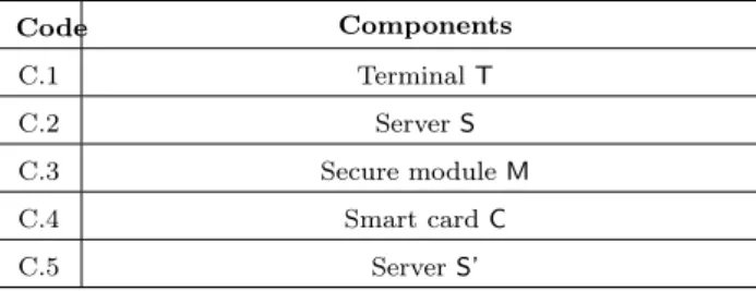
Code Components C.1 Terminal T C.2 Server S C.3 Secure module M C.4 Smart card C C.5 Server S’
Table 1: Generic components of a biometric access control system
time stamp tsi along with the user’s identity IDi, for all users. Since access traces reveal
information about users, they are usually stored as eat, i.e., encrypted with a key kat.
The components of a biometric access control system usually include a terminal T used to collect raw biometric data and a server S used to store information about users. In some cases, specific components such as a secure module M, a smart card C or a second server S’ may also be used. The locations of the comparison and the storage of
the encrypted biometric templates ebri may vary depending on the architecture of the
system. The encrypted template may be stored on the server or on a smart card. Secure modules and smart cards are assumed to be tamper proof: only the actors controlling them can get access to their data. The components along with their code names are
specified in Table1.
4.2 Definition of generic data
The next step is the definition of the personal data processed by the system, which can be
derived from its specification. Table 2 presents this list for the biometric access control
system considered here. In a given architecture, each of these data is stored in one or
more components, permanently or transiently. For example, the enrolled template ebri
is typically stored permanently in a database, and also transiently in a component that
compares it with a fresh template. We assume that some data such as bri and ebri are
always associated with IDi during enrolment (hence the use of bri and ebri following the
notation convention introduced above). So when a risk source has access to bri, it has
also access to IDi. For other data such as rdi and bsi, the identity IDi may or may
not be collected directly from the user during the access control. Therefore, we do not
assume that they are inherently associated with IDi. For example, in some scenarios,
the user may be required to present a smart card containing his identity IDi which is
never transmitted to any of the components controlled by the owner (so that there is no
trace of IDi in these components even though they may host rdi and bsi).
4.3 Definition of generic risk sources
We assume that each component may be controlled either by the system owner (data controller in the GDPR) or by a security operator (data processor in the GDPR) acting as a sub-contractor of the owner. The exact components controlled by each actor depend on
Code Data IDi Identity of user i
bri Biometric reference template of user i
ebri Encrypted biometric reference template of
user i
ebr Encrypted database of biometric templates for all users
rdi Raw biometric data for user i
bsi Fresh biometric template derived from rdi
deci Result of an access control check for user i
tsi Time stamp associated with an access control
of user i
at Access log of all users containing decand ts i, IDi
ifor all i
ac Access control rules kbr Key used to decrypt ebr
kat Key used to decrypt at
eat Encrypted at
thr Threshold for comparing bsiand bri
Code Risk Sources
A.1 Owner of the access control system A.2 Security operator
A.3 Hacker
A.4 Government
A.5 Third parties
Table 3: Generic risk sources for biometric access control system
the architecture. For example, in some architectures, the security operator may control only the component performing the comparison. In other architectures, it may also
control the component storing the reference templates. Table3 presents a set of generic
risk sources for the system. In addition to the system owner (A.1) and the security operator (A.2) who are internal risk sources, hackers (A.3) and governments (A.4) may act as external risk sources. In some cases, the system owner or the security operator may have business links with third parties (A.5) such as insurance providers, marketing companies, which may also become risk sources. In a real privacy risk analysis, other risk sources such as employees of the owner and the operator should also be considered, but we do not discuss them here for space considerations.
4.4 Definition of generic privacy harms
The possibility for a risk source to get access to access control results and access logs makes the users of the system vulnerable to surveillance. Surveillance may also result from the misuse of biometric templates. It may be carried out by risk sources such as the system owner itself or the government with different motivations. For example, an employer may try to find out how frequently a particular employee takes breaks based on the number of times he accesses the office cafeteria. Harms occur when surveillance takes place beyond the intended purpose of the access control system. Identity theft is another important concern for biometric access control systems. It can be caused by wrongful access to biometric reference templates, fresh biometric templates or even raw biometric
data along with user identity. Table4 presents these two generic privacy harms. Other
harms are also possible (e.g., inference of sensitive attributes such as health related or
genetic information, weight or body mass index [6,27,32]), but we do not discuss them
here because of space limitations.
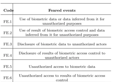
4.5 Definition of generic feared events
Harms result from the combination of one or more feared events. Generally speaking, we distinguish three types of feared events resulting from, respectively, the access to personal data, the use of personal data, and the disclosure of personal data. We consider two main types of personal data here, biometric data and access control results, which
Code Harm Scenarios
H.1 Surveillance
Tracking users outside the expected use (declared purpose) of the access control system (e.g., an employer finding out the number of breaks employees take from a biometric access control system meant to restrict the office cafeteria only to
employees)
H.2 Identity theft
Using the biometric data of a person for wrongful identification (e.g., a hacker using the user’s fingerprint data to gain access to a restricted
area)
Table 4: Generic privacy harms for biometric access control system
Code Feared events
FE.1 Use of biometric data or data inferred from it forunauthorized purposes FE.2 Use of result of biometric access control and datainferred from it for unauthorized purposes FE.3 Disclosure of biometric data to unauthorized actors
FE.4 Disclosure of results of biometric access control to unauthorized actors
FE.5 Unauthorized access to biometric data FE.6 Unauthorized access to results of biometric access
control
4.6 Construction of generic harm trees
Generic harm trees can be constructed corresponding to the harms discussed in Section
4.4using the system components, risk sources and feared events identified in the previous
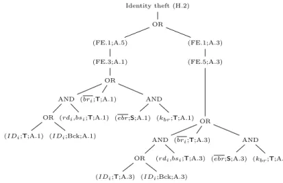
subsections. In this section, we discuss only the generic harm tree for identity theft (H.2)
(Figure2). The interested reader can find the generic harm tree for surveillance (H.1) in
AppendixB. Generic harm trees take into account all possible components, risk sources
and data. They can be refined to specific components and risk sources when the details
of the architectures and the context are available (Section 5and Section 6). We use the
notation C.i, C.k, etc. to denote generic components (which will be instantiated in the next phases) in the trees.
Iden tit y theft (H.2) OR (FE.1;A.5) OR (FE.3;A.1) OR AND OR ( I D i ;C.j;A.1) ( I D i ;Bc k ;A.1) ( r di ,bs i ;C.k;A.1) ( br i ;C.l;A.1) AND ( ebr ;C.m;A.1) ( kbr ;C.n;A.1) (FE.3;A.2) OR AND OR ( I D i ;C.j;A.2) ( I D i ;Bc k ;A.2) ( r di ,bs i ;C.k;A.2) ( br i ;C.l;A.2) AND ( ebr ;C.m;A.2) ( kbr ;C.n;A.2) (FE.1;A.3) (FE.5;A.3) OR AND OR ( I D i ;C.j;A.3) ( I D i ;Bc k; A.3) ( r di ,bs i ;C.k;A.3) ( br i ;C.l;A.3) AND ( ebr ;C.m;A.3) ( kbr ;C.n;A.3) Figure 2: Generic har m tree for iden tit y theft (H.2) (Phase 1)
Figure2shows that the harm identity theft (H.2) can be caused by the use of biometric data for unauthorized purposes (FE.1). FE.1 itself can be caused by a hacker (A.3) via unauthorized access to biometric data (FE.5) or by third parties (A.5) which are unauthorized actors receiving biometric data (FE.3) from either the security operator (A.2) or the owner (A.1). FE.3 and FE.5 may be caused by the exploitation of different data items in one or more components of the system (which are pictured by the leaves in the harm trees). Commas in the leaves are used as concise notations for disjunctions
(e.g., rdi, bsi means rdi OR bsi).
Although theoretically possible, some combinations of risk sources and harms do not make sense in practice, irrespective of the details of the architecture or the context. For example, the system owner, the operator and the government are unlikely to perform identity theft. These combinations are left out of the generic harm trees. Therefore,
Figure2 does not have a branch where FE.1 is carried out by A.1 or A.2 or A.4.
IDi may be obtained by a risk source either from a system component or as
back-ground information. These possibilities are differentiated by an OR subtree with two children in the harm trees. The abbreviation ‘Bck’ denotes background information. We assume that all other data elements can be obtained only from a system component (they are unlikely to be known as a background information by a risk source).
The generic harm tree only considers the most likely risk sources (with or without collusion) that may lead to a harm. When a harm is possible both via a single risk source or a collusion of risk sources, only the single risk source is represented (since it is less demanding and therefore more likely).
5
Phase 2: Architecture-specific Privacy Risk Analysis
This phase takes as input the architecture(s) under consideration and specific system components (if any). Its goal is to refine the generic harm trees resulting from Phase 1 to obtain harm trees specific to each architecture.
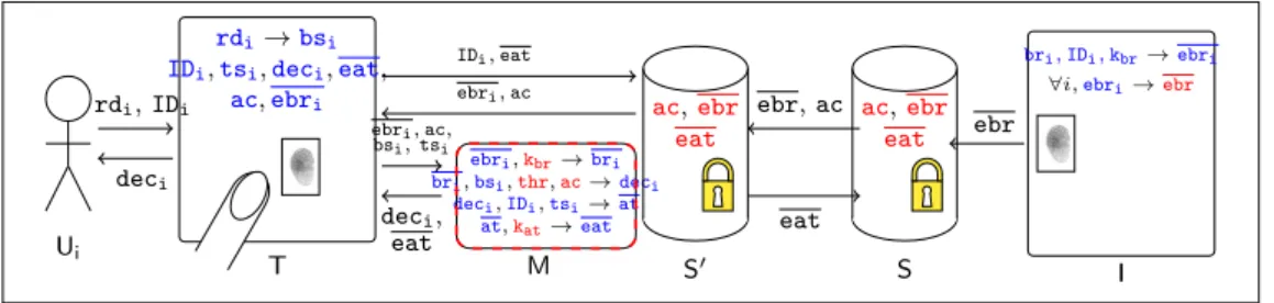
Figure 3 shows the graphical representations of the biometric access control
com-ponents used in this report. In the following subsections, the user and the enrolment site are not considered within the scope of the system. The issuer I is only involved in the enrolment phase. It is in charge of collecting and encrypting the enrolled biometric
reference templates bri along with user identities IDi into ebri and storing them in the
form of the database ebr in the server S. It has no role during the access control process.
I is shown in Figure4and Figure6 for the sake of clarity only.
5.1 Arch.1: Use of an Encrypted Database
5.1.1 Description of Arch.1
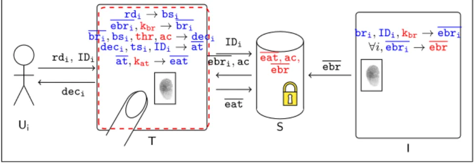
We first consider the simple biometric access control architecture pictured in Figure 4.
The server S stores the database of encrypted reference templates ebr and the access
control rules ac. When the user presents his identity IDi and fresh biometric rdi to the
User Encrypted
database Terminal Card
Location of the comparison
Figure 3: Graphical representation of biometric access control systems
Ui rdi, IDi deci T rdi→bsi ebri,kbr→bri bri,bsi,thr,ac→deci deci,tsi,IDi→at at,kat→eat IDi ebri, ac eat S eat, ac, ebr ebr I bri,IDi,kbr→ebri
∀i,ebri→ebr
Figure 4: Architecture Arch.1 : Encrypted database
key kbr and compares bri with bsi produced from rdi by T (taking into account thr).
The access control decision deci is used to allow or deny access. The access logs at of
different users are encrypted into eat and sent back by the terminal T at regular intervals to be stored in the server S. The access log at is updated after each access control.
The keys4 k
at and kbr, the threshold thr and access control rules ac are persistently
stored in the terminal T5. In contrast, at is stored in T only for short time intervals.
deci, rdi, bsi, bri, tsi, at, eat, ebri, IDi are deleted from the terminal T as soon as their
use is over6.
The components in this architecture are therefore: the terminal T (C.1) and the server S (C.2).
5.1.2 Risk sources for Arch.1
Since the architecture does not include any security components, we assume that no security operator is involved. The risk sources are therefore: the owner (A.1), hackers (A.3), the government (A.4) and third parties (A.5). The owner (A.1) controls both the server S and the terminal T.
4Keys are assumed to be protected by techniques which are not discussed here (e.g. obfuscation).
5Data elements that are stored persistently in a component are marked in red in Figure4, Figure6
and Figure8.
6Data elements that are stored transiently in a component are marked in blue in Figure4, Figure6
System
component Data Exploitability T deci Persistent exploit of T
T IDi Persistent exploit of T
T at Transient exploit of T S eat Transient exploit of S T kat Transient exploit of T
T kbr Transient exploit of T
T ebri Persistent exploit of T
T bri Persistent exploit of T
S ebr Transient exploit of S T rdi, bsi Persistent exploit of T
Table 6: Personal data in Arch.1 and their exploitability values
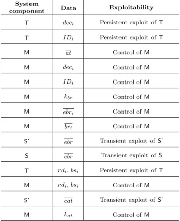
5.1.3 Personal data for Arch.1 and their exploitability
At this stage, the privacy analyst presents each data element stored in each system
component and its exploitability (see Table 6). As explained in Section2, by “transient
exploitation” of a component we mean exploitation for a short period of time or infrequent exploitation, (e.g., once in several months), whereas “persistent exploitation” means the exploitation of a component for a long period of time (e.g., for several days or months).
For example, deci provides the result of one access control for user i, whereas at provides
the access log of all users for all previous days. So to know the access log of all users
over t days, the risk source must either access all deci for all users for each of the t days
(persistent exploitation) or access at at the end of the t days (transient exploitation).
5.1.4 Refinement of generic harm trees for Arch.1
In this phase, we consider the harm identity theft (H.2). Figure5 shows the harm tree
corresponding to this harm. Figure12 in Appendix A shows how the generic harm tree
(Figure 2) for identity theft is pruned to obtain the architecture specific harm tree in
Figure 5. From Section 5.1.2, we know that the risk sources for Arch.1 do not include
A.2. Therefore, all branches of the generic harm tree for identity theft (H.2) that contain
A.2 are pruned (pruned branches are marked by a red cross in Figure12). The definition
of the architecture also makes it possible to instantiate the generic components Ci, Cj,
(FE.1;A.5)
(FE.3;A.1)
OR
AND
OR
(IDi;T;A.1) (IDi;Bck;A.1)
(rdi,bsi;T;A.1) (bri;T;A.1) AND (ebr;S;A.1) (kbr;T;A.1) (FE.1;A.3) (FE.5;A.3) OR AND OR
(IDi;T;A.3) (IDi;Bck;A.3)
(rdi,bsi;T;A.3)
(bri;T;A.3) AND
(ebr;S;A.3) (kbr;T;A.3)
Figure 5: Identity theft (H.2) harm tree for architecture Arch.1
5.2 Arch.2: Encrypted Database with a Hardware Security Module
5.2.1 Description of Arch.2
In Arch.1, the clear reference template bri is available in T. Since T can have
vulnera-bilities and can be placed in more or less accessible places, a better data protection can be achieved by utilizing a hardware security module M to perform the comparison of the fresh template with the enrolled template, thus preventing the need to make the clear template available in the terminal T. Arch.2 also introduces a security operator (A.2) to manage M.
In Arch.2 (pictured in Figure6), the server S stores the database of encrypted
refer-ence templates ebr and the access control rules ac as in Arch.1. A second server S’ stores
ebr (updated periodically from S to take new enrolments into account), ac (updated
periodically from S) and eat (updated periodically by T).
When a user presents his identity IDi and fresh biometric rdi to the terminal T,
T transfers to M, a hardware security module (HSM), the identity IDi along with bsi
derived from rdi and ebri fetched from S’. M decrypts ebri using key kbr and compares
bri with bsi (taking into account thr). The output deci is transferred back to terminal
Tand used to grant or deny access (based on ac, a copy of which is also made available
in M). The access logs at are encrypted into eat by M and sent to T which stores it into
S’. T, M and S’ are controlled by the security operator, whereas S is controlled by the
owner.
The separate server S’ controlled by the security operator (A.2) prevents the owner
(A.1) from knowing the identity IDi of a user requesting access. Moreover, the owner
does not have access to clear biometric templates or results of access control checks. Therefore the owner cannot carry out any surveillance or disclose biometric data to other risk sources. The owner’s role is to devise access control rules, enroll users and update the security operator A.2 about ac and ebr from time to time. The owner maintains a
Ui rdi, IDi deci T rdi→bsi IDi,tsi,deci,eat, ac,ebri bsi, tsi ebri, ac, deci, eat M ebri,kbr→bri bri,bsi,thr,ac→deci deci,IDi,tsi→at at,kat→eat ebri, ac IDi, eat S ac,ebr eat S0 ac,ebr eat ebr ebr, ac eat I bri, IDi, kbr→ebri
∀i,ebri→ebr
Figure 6: Architecture Arch.2 : hardware security module (HSM) copy of eat for future reference (e.g., in case of a dispute with the user).
The keys kat and kbr, the threshold thr and access control rules ac are stored in M.
The decision deci is erased just after its use. Similarly, rdi, bsi, ebri, bri, eat, tsi, at,
IDi, and tsiare deleted from the components (i.e., T and M) which use or generate them
as soon as their use is over.
The system components in this architecture are the terminal T (C.1), the servers S (C.2) and S’ (C.5) and the hardware security module M (C.3).
5.2.2 Risk sources for Arch.2
All risk sources have to be considered for Arch.2: the owner (A.1), the security operator (A.2), hackers (A.3), the government (A.4) and third parties (A.5). We assume that the server S is controlled by the owner (A.1) and the security operator (A.2) controls the hardware security module M, the terminal T and the server S’. M is assumed to be secure and therefore cannot be (or is very unlikely to be) attacked.
5.2.3 Personal data and their exploitability values for Arch.2
Table 7 presents the personal data stored in each component. A risk source must have
enough technical resources to exploit S or S’ transiently. Since it is a secure component,
a risk source must have control on M to access its data. In Arch.2, kbr and kat are stored
only in M. So, A.1, A.3 and A.4 cannot get access to them.
5.2.4 Refinement of generic harm trees for Arch.2
Figure13 in Appendix Ashows how the generic harm tree for identity theft (H.2)
(pre-sented in Figure 2) can be pruned to derive the corresponding harm tree for Arch.2
(presented in Figure 7). In Arch.2, the owner of the system (A.1) has access only to S.
Moreover, M is assumed to be a secure component. Therefore, no data element on any component other than S is accessible to A.1. So, A.1 can only access ebr (assuming that A.1 is unlikely to attack T for disclosing data to third parties, i.e., A.5). However, to be
able to exploit ebr, the owner A.1 also needs to have access to kbr which is out of his reach
since it is stored only in M. So, the branches in Figure 13 where A.1 needs access to bri
System
component Data Exploitability T deci Persistent exploit of T
T IDi Persistent exploit of T M at Control of M M deci Control of M M IDi Control of M M kbr Control of M M ebri Control of M M bri Control of M
S’ ebr Transient exploit of S’ S ebr Transient exploit of S T rdi, bsi Persistent exploit of T
M rdi, bsi Control of M
S’ eat Transient exploit of S’
M kat Control of M
secure component M which contains bri and kbr. So the corresponding branches are also
pruned. Both rdi and bsi are accessible to the security operator A.2 as it controls both
M and T. In the harm trees, for simplicity, we only show A.2’s access to bsi in M. The
definition of the architecture also makes it possible to instantiate the generic components
Ci, Cj, Ck, Cl, Cm and Cn.
5.3 Arch.3: Match-on-Card Technology
5.3.1 Description of Arch.3
Arch.2 is more protective than Arch.1 as the former uses a secure component M to perform the comparison between the fresh template and the reference template. In addition, it involves a security operator (A.2) for a better separation of responsibilities. However, in
Arch.2, the fresh reference template bsi is still available in T along with IDi. Moreover,
the clear template brican still be accessed by the security operator (A.2) who controls M.
In fact, A.2 has access to a lot of personal data. One way to overcome these difficulties is
to use the match-on-card technology. In Arch.3, pictured in Figure8, each user possesses
a smart card C that stores his identity IDi along with his enrolled template bri (i.e.,
it stores bri), the threshold thr and access control rules ac and performs the matching
operation without disclosing IDi or bri to the terminal T. The owner does not store any
database of reference templates.
The user inserts the card into the terminal T and submits the fresh biometric raw
data rdi. T derives a fresh template bsi from rdi and transfers it to C. C compares bsi
with briusing the threshold thr and transfers the result of the access control deci to T. T
informs the user about deci and sends it to the physical access control mechanism. The
card C does not transfer any information apart from deci (not even the user identity IDi)
to T. C is assumed to be completely secure (e.g., it is tamper-resistant and personalized
by a certified issuer during the enrolment phase). Both rdi and bsi as well as deci are
deleted from T and C as soon as their uses are over. No access log at is recorded. The system components in this architecture are: the terminal T (C.1) and the smart card C (C.4).
5.3.2 Risk sources for Arch.3
We assume that there is no security operator (A.2) in this architecture, since the security relies only on the smart cards possessed by the users. Therefore, the risk sources to be considered include: the owner (A.1), hackers (A.3), the government (A.4) and third parties (A.5). The owner (A.1) controls the terminal T.
5.3.3 Personal data and their exploitability for Arch.3
Table8presents each data item stored in each system component and the corresponding
exploitability values for Arch.3. A risk source must have enough technical resources to
exploit T persistently to get access to deci, rdi or bsi. However, in contrast with Arch.1
(FE.1;A.5)
(FE.3;A.2)
OR
AND OR
(IDi;M;A.2) (IDi;Bck;A.2)
(bsi;M;A.2) (bri;M;A.2) AND (ebr;S’;A.2) (kbr;M;A.2) (FE.1;A.3) (FE.5;A.3) AND OR
(IDi;T;A.3) (IDi;Bck;A.3)
(rdi,bsi;T;A.3)
Figure 7: Identity theft (H.2) harm tree for architecture Arch.2
Ui T Ci rdi deci rdi→bsi deci bsi deci
bsi,bri,thr,ac→deci
Figure 8: Architecture Arch.3 : Match-On-Card technology
or rdi, bsi, risk sources must have IDias background information. Since C is considered
to be secure and belongs to the user, it does not appear in Table8.
5.3.4 Refinement of generic harm trees for Arch.3
Figure14 in Appendix Ashows how the generic harm tree for identity theft (H.2)
(pre-sented in Figure 2) can be pruned to derive the corresponding harm tree for Arch.3
(presented in Figure 9). In Arch.3, IDi, bri, ebri and kbr are not present at any
mo-ment in any of the components that the risk sources may access (i.e., terminal T). So all branches in the generic tree corresponding to these data elements are pruned. Also, the risk source A.2 is not a part of Arch.3. So all branches concerning A.2 are pruned
System
component Data Exploitability T deci Persistent exploit of T
T rdi, bsi Persistent exploit of T
Identity theft (H.2)
OR
(FE.1;A.5)
(FE.3;A.1)
AND
(IDi;Bck;A.1) (rdi,bsi;T;A.1)
(FE.1;A.3)
(FE.5;A.3)
AND
(IDi;Bck;A.3) (rdi,bsi;T;A.3)
Figure 9: Identity theft (H.2) harm tree for architecture Arch.3
too. The definition of the architecture also makes it possible to instantiate the generic
components Ci, Cj, Ck, Cl, Cm and Cn.
6
Phase 3: Context-specific Privacy Risk Analysis
As described in Section 3, the objective of Phase 3 is to take into account all context
specific factors. The harm trees specific to each architecture produced in Phase 2
(Sec-tion 5) are further pruned based on the specific context to be considered. Then, the
likelihoods of the harms are computed based on these pruned trees, the exploitability values of the data and the capacities of the risk sources. The ultimate decision as to which architecture(s) is (are) more suitable can be taken based on these likelihoods and the severity of the harms. As discussed before, this decision may also generally involve other non-technical considerations.
6.1 Definition of the context
In this report, we use casinos as an illustrative example of context. Casinos have to put in place strict checks to prevent the entry of individuals who are minors or blacklisted. To increase the efficiency of identity checks, some casinos want to implement biometric verification systems to control the access of frequent customers. Users (frequent cus-tomers here) have to be initially enrolled by the owner (the casino here) to verify their identity. At this stage, the owner may also provide other relevant information (such as
the location of the casino7) that may later be useful to determine the capabilities and
motivations of the risk sources.
7For example, different locations correspond to different applicable laws (the motivation of a risk
source may vary depending on the existence of data protection regulations and how strongly they are
enforced), the strength (e.g., technical resources) or motivation of the local government to interfere [25],
(FE.1;A.5)
(FE.3;A.1)
OR
AND
(IDi;T;A.1) (rdi,bsi;T;A.1)
(bri;T;A.1) AND (ebr;S;A.1) (kbr;T;A.1) (FE.1;A.3) (FE.5;A.3) OR AND
(IDi;T;A.3) (rdi,bsi;T;A.3)
(bri;T;A.3) AND
(ebr;S;A.3) (kbr;T;A.3)
Figure 10: Identity theft (H.2) final harm tree for architecture Arch.1
6.2 Definition of the background information available to risk sources
We assume that in this context, none of the risk sources is likely to possess the identity
of the users as background information8. By availability of ID
i, we mean the availability
of any information that can reveal IDi.
6.3 Definition of the technical resources available to the risk sources
The system owner (A.1) and the security operator (A.2) are assumed to have technical resources for the transient exploitation of all components over which they do not have control. Third parties (A.5) also have technical resources for this transient exploitation. The government (A.4) and hackers (A.3) are assumed to have technical resources for persistent exploitation of any component.
The access rights of each risk source for each architecture have already been specified in Phase 2. For each architecture, the capabilities of each risk source can be derived by comparing the exploitability of the data and their technical resources and access rights. A risk source having control over a component has the highest capability (with respect to the data stored on this component) because it can exploit it irrespective of the exploitability value. A risk source having technical resources for persistent exploitation also has high capability for data for which the exploitability value is persistent or transient and low otherwise. A risk source having technical resources for transient exploitation only has high capability for data with exploitability value equal to transient and low otherwise.
8This assumption should be valid at least for large scale attacks. However, one could argue that
casinos may possess background information about certain frequent customers. Similarly, the government would be considered as having potentially a lot of background information but it is a more relevant risk source for surveillance than for identity theft. In any case, the assumptions made in this report are for illustrative purposes only: different assumptions about background information could be made within the same framework.
Identity theft (H.2) OR (FE.1;A.5) (FE.3;A.2) OR AND
(IDi;M;A.2) (bsi;M;A.2)
(bri;M;A.2) AND
(ebr;S’;A.2) (kbr;M;A.2)
(FE.1;A.3)
(FE.5;A.3)
AND
(IDi;T;A.3) (rdi,bsi;T;A.3)
Figure 11: Identity theft (H.2) final harm tree for architecture Arch.2
6.4 Definition of the motivation of the risk sources
The motivations for the exploitation of data are derived from the motivations of the risk sources for the corresponding feared events and harms. When the parent and child feared events are caused by different risk sources, then the motivation of the parent feared event may be different from that of the child feared event depending on the risk source causing each. In that case, in order to err on the safe side, the maximum of the motivations is considered. When the parent and child feared events are caused by the same risk source, the motivation value for the parent feared event is taken into account.
6.5 Final pruning of harm trees
The specific harm trees produced in Phase 2 can be further pruned depending on the
contextual information (as described in sections 6.2, 6.3 and 6.4). For example, for
the harm tree for Arch.3 pictured in Figure 9, we observe that IDi appears only as
background information. As discussed in Section 6.2, it is unlikely that any of the risk
sources will possess IDi as background information. Hence, the corresponding branch
can be pruned. In the absence of IDi, neither rdi nor bsi can be exploited. So these
branches in the harm tree can also be pruned and the resulting tree is empty which means that this harm can be discarded (or is very unlikely to occur) for Arch.3. This pruning
is shown in Figure15in AppendixA. Similarly, for Arch.1 and Arch.2, all branches with
IDias background information are pruned. The pruned trees are shown in Figure10and
Figure11. Generally speaking, the context is of prime importance to distinguish relevant
and irrelevant combinations of harms and risk sources. For example, casino owners are unlikely to track their customers beyond the purpose of the access control system. In contrast, an employer may be tempted to track his employees (e.g., to know how many breaks they take) beyond the purpose of the biometric access control system (e.g., to restrict the access of a cafeteria only to employees).
Owner (A.1) FE.3, FE.4,
FE.5, FE.6 Medium Security operator
(A.2)
FE.1 Low (for H.2), High(for H.1) FE.3, FE.4 Medium Hacker (A.3) FE.1 High (for H.2) Government (A.4) FE.1, FE.2 High (for H.1) Third party (A.5) FE.1 Medium (for H.2)
Table 9: Relevant risk sources and their motivations in the casino context
6.6 Computation of likelihoods based on harm trees
The computation of the likelihood of the harms based on the final harm trees can be carried out in two steps:
1. The first step is the assessment of the likelihood of the leaves of the harm trees (likelihood of exploitation of personal data) from the motivation and the capability
of the relevant risk sources. This assessment is based on Table9 and Table10.
2. The second step is the computation of the likelihood of each feared event and harm
according to the following rules (applied bottom-up), where Pi is the likelihood of
the ith child node:
R1. AND node with independent child nodes: QiPi.
R2. AND node with dependent child nodes9: Min(P
i), i.e., minimum of the
like-lihoods of the child nodes.
R3. OR node with independent child nodes: 1 − Qi(1 − Pi).
R4. OR node with dependent child nodes10: Min(1, P
iPi).
To perform the computations of the second step, it is necessary to translate the
symbolic likelihood values of Table10into numerical values. This transformation has to
be made by the privacy expert in collaboration with the owner and should be documented. In this report, we use as an illustration the following correspondance for the likelihood values (p):
1. Negligible (N): p < 0.01%; 2. Limited (L): 0.01% ≤ p < 0.1%;
9In order to err on the safe side in terms of privacy protection, we consider dependent nodes such
that one node may imply the other nodes.
10In order to err on the safe side in terms of privacy protection, we consider dependent nodes such
3. Intermediate (I): 0.1% ≤ p < 1%; 4. Significant (S): 1% ≤ p < 10%; 5. Maximum (M): p ≥ 10%.
Figure16in AppendixAdepicts the computation of the likelihood for H.2 for Arch.3.
The likelihoods of the two harms considered here for the three architectures can be
computed similarly (see Table 11). Needless to say, the analysis could lead to different
results for different scenarios or different assumptions.
6.7 Choice of architecture
The results of the previous sections can be used by the owner (with the help of the privacy expert and, ideally, after consultation of the stakeholders in the context of a Pri-vacy Impact Assessment) to decide upon an acceptable likelihood for each harm. Based
on Table 11, and the acceptable threshold, he can then select one or more acceptable
architectures or decide to enhance them with further privacy protection measures. Let us assume that the system designer decides that the acceptability threshold for each of harm is “limited”. Then, none of the architectures is acceptable. However, if the owner accepts ‘Significant’ risks of government surveillance, then Arch.3 is the only acceptable architecture. Another scenario could be that the owner is ready to accept risks (for his customers) related to surveillance by the government and would like to use Arch.2, es-pecially because he does not want to manage the process related to the distribution and management of smart cards. Then, he has to decide (in collaboration with a privacy expert) upon additional counter-measures to reduce the risks. The harm tree in Figure
16 is a key source of information to make this decision. It shows that the target should
be to better protect the terminal from hackers.
7
Related Works
As argued in [5], the privacy by design principle does not provide any specific guideline to
translate legal data protection requirements into system requirements. To address this
problem, Hoepman [18] has introduced the concept of “privacy design strategies” and
proposed eight such strategies derived from existing privacy principles and data
protec-tion laws. Recently, Colesky et al. [5] have refined the definitions of these strategies and
introduced an additional layer of abstraction, referred to as “tactics”, which contribute to each privacy design strategy. For example, the data minimization strategy can be achieved by adopting tactics such as not processing personal data or removing unnec-essary personal data from the system. Tactics help to bridge the gap between privacy
design strategies and privacy design patterns [14,16,17] which guide designers and
pre-vent them from “re-inpre-venting the wheel”. However, even if the availability of catalogues of privacy design strategies, tactics and patterns can be very useful, it does not in itself
Negligible Low Low Limited High Negligible Low Medium Significant High Limited Low High Maximum High
Table 10: Measurement rule for likelihood of exploitation
of data minimization, through a detailed study of the activities performed by privacy engineers in deciding the right data minimization strategies to be applied.
Spiekermann and Cranor [29] also discuss the privacy engineering process and
intro-duce a distinction between “privacy-by-policy” and “privacy-by-architecture”. Pearson
and Benameur [26] propose a decision support system based on “privacy-by-policy”, to
provide system developers with relevant privacy design patterns. Based on the privacy requirements and the context given as inputs by the developers, the decision support sys-tem uses the rule repository and the abstract representations to obtain a set of patterns
suitable to the given scenario. In contrast, Hoepman [18] adopts a mixed approach, with
the view that neither the system architecture nor a privacy policy alone can guarantee privacy. Their privacy design strategies help system designers to engineer privacy from both perspectives.
In contrast with the above approaches, we do not propose a methodology to build new architectures here, but rather to select an architecture among a range of options and to justify this choice with respect to a privacy risk analysis. Our work is therefore complementary to the above proposals. The need to take into account the actual privacy
risks or threats is mentioned in most of these papers [15,26,29] but, to our best knowledge,
has not been explored in detail in previous works.
Similar types of trees (sometimes called “threat trees” or “attack trees”) have already
been used for privacy risk analysis [7,8,10,11,24]. However, the focus of the work
described here is not the risk analysis itself, but its adaptation and application to the architecture selection process. To this aim, we introduce generic harm trees and show how they can be successively refined.
Most works on the privacy of biometric systems [19,21,22,30] have been carried out
at a lower level than the architectures discussed here. The only counter-example, to the best of our knowledge, is the application of a formal framework to biometric access
control architectures [2]. In contrast to this work, we propose a general approach based
Surveillance by the government (H.1,A.4) Identity theft (H.2) Encrypted Database
(Arch.1) Maximum Maximum
HSM (Arch.2) Maximum Significant Match-on-Card
(Arch.3) Significant Negligible
Table 11: Comparison of the likelihoods of harms
8
Conclusion and Future Work
In this report, we have discussed a novel approach for a better integration of privacy risk analysis and privacy by design. We believe that such an integration is of prime importance in practice, especially in the context of the GDPR, which promotes both data protection impact assessments and privacy by design. The three-phase process described here provides further benefits such as:
1. Enhanced clarity of the privacy risk analysis phase through a better separation of concerns.
2. Re-use and capitalization of results: only the third phase has to be reconsidered in case of a change in the context; only the second and third phases for changes in the architectures. Phase 1 needs to be updated only when new types of privacy harms, feared events or risk sources emerge for a given system. This phase can be seen as a preliminary risk analysis valid for a whole line of products.
One of the advantages of the order chosen here (considering first the specification, then the architectures and finally the context) is that the provider of a given solution (relying on a specific architecture) can build on the results of the second step to derive refined trees for different contexts (e.g. for different customers). In some situations however, it might be more efficient to consider the context before the architectures (e.g. to discard irrelevant harms). Space considerations prevent us from describing this option here but it is essentially a variant of the methodology described in this report.
We have also not discussed certain features of the harm trees that can turn out to be useful in other contexts or for other systems or architectures. For example, harm trees can include information about the possibility of collusion among risk sources. The motivations of the risk sources have to be properly defined when collusions are taken into
account. In the harm trees considered here, only IDi can be available as background
information. For other harms, other data items (such as location data) can also be included as background information.
Last but not least, further types of risks (such as unavailability or loss of integrity) and considerations (such as usability and cost) have to be taken into account in practice. Any privacy risk that can be analyzed using harm trees can be dealt with by our methodology. As far as usability and costs are concerned, they have to be integrated in the decision
References
[1] BBC Technology. Millions of Fingerprints Stolen in US Government Hack, 2015. [2] Julien Bringer, Hervé Chabanne, Daniel Le Métayer, and Roch Lescuyer. Privacy
by design in practice: Reasoning about privacy properties of biometric system ar-chitectures. In FM 2015: Formal Methods - 20th International Symposium, Oslo,
Norway, June 24-26, 2015, Proceedings, pages 90–107, 2015.
[3] Ann Cavoukian, Michelle Chibba, and Alex Stoianov. Advances in Biometric En-cryption: Taking Privacy by Design From Academic Research to Deployment.
Re-view of Policy Research, 29(1):37–61, 2012.
[4] Ann Cavoukian and Alex Stoianov. Privacy by Design Solutions for Biometric
One-to-Many Identification Systems. 2014.
[5] Michael Colesky, Jaap-Henk Hoepman, and Christiaan Hillen. A Critical Analysis of Privacy Design Strategies. In 2016 IEEE Security and Privacy Workshops, SP
Workshops 2016, San Jose, CA, USA, May 22-26, 2016, pages 33–40, 2016.
[6] Antitza Dantcheva, Petros Elia, and Arun Ross. What Else Does Your Biometric Data Reveal? A Survey on Soft Biometrics. 2015.
[7] Sourya Joyee De and Daniel Le Métayer. PRIAM: A Privacy Risk Analysis Method-ology. In 11th International Workshop on Data Privacy Management (DPM). IEEE, 2016.
[8] Sourya Joyee De and Daniel Le Métayer. Privacy Harm Analysis: A Case Study on Smart Grids. In International Workshop on Privacy Engineering (IWPE). IEEE, 2016.
[9] Sourya Joyee De and Daniel Le Métayer. Privacy Risk Analysis. In Synthesis Series. Morgan & Claypool Publishers, 2016.
[10] Sourya Joyee De and Daniel Le Métayer. PRIAM: A Privacy Risk Analysis Method-ology. INRIA Research Report, (RR-8876), July, 2016.
[11] Mina Deng, Kim Wuyts, Riccardo Scandariato, Bart Preneel, and Wouter Joosen. A Privacy Threat Analysis Framework: Supporting the Elicitation and Fulfilment of Privacy Requirements. Requirements Engineering, 16(1):3–32, 2011.
[12] European Commission. Regulation (EU) 2016/679 of the European Parliament and of the Council of 27 April 2016 on the protection of natural persons with regard to the processing of personal data and on the free movement of such data, and repealing Directive 95/46/EC (General Data Protection Regulation), 2016.
[13] Claire Gartland. Biometrics Are a Grave Threat to Privacy, 2016. The New York Times.
[14] Seda Gürses, Carmela Troncoso, and Claudia Diaz. Engineering Privacy by Design.
Computers, Privacy & Data Protection, 14(3), 2011.
[15] Seda Gürses, Carmela Troncoso, and Claudia Diaz. Engineering Privacy by Design Reloaded. 2015.
[16] Munawar Hafiz. A Collection of Privacy Design Patterns. In Proceedings of the 2006
conference on Pattern languages of programs, page 7. ACM, 2006.
[17] Munawar Hafiz. A Pattern Language for Developing Privacy Enhancing Technolo-gies. Software: Practice and Experience, 43(7):769–787, 2013.
[18] Jaap-Henk Hoepman. Privacy Design Strategies. In IFIP International Information
Security Conference, pages 446–459. Springer, 2014.
[19] Alper Kanak and Ibrahim Sogukpinar. BioPSTM: A Formal Model for Privacy, Security, and Trust in Template-protecting Biometric Authentication. Security and
Communication Networks, 7(1):123–138, 2014.
[20] Nicole Kobie. Surveillance State: Fingerprinting Pupils Raises Safety and Privacy Concerns, 2016. The Guardian.
[21] Lifeng Lai, Siu-Wai Ho, and H Vincent Poor. Privacy–Security Trade-Offs in Bio-metric Security Systems?Part I: Single Use Case. IEEE Transactions on Information
Forensics and Security, 6(1):122–139, 2011.
[22] Lifeng Lai, Siu-Wai Ho, and H Vincent Poor. Privacy–Security Trade-Offs in Biomet-ric Security Systems?Part II: Multiple Use Case. IEEE Transactions on Information
Forensics and Security, 6(1):140–151, 2011.
[23] Sanjeev Miglani and Manoj Kumar. India’s Billion-member Biometric Database Raises Privacy Fears, 2016. Reuters.
[24] Miguel Nunez del Prado Cortez and Jesús Friginal. Geo-Location Inference At-tacks: From Modelling to Privacy Risk Assessment. In Tenth European Dependable
Computing Conference (EDCC), pages 222–225. IEEE, 2014.
[25] Casey Oppenheim. Big Brother Spying is Reaching Scary Levels. http://edition.
cnn.com/2013/12/10/opinion/oppenheim-privacy-reform/, 2013.
[26] Siani Pearson and Azzedine Benameur. A Decision Support System for Design for Privacy. In IFIP PrimeLife International Summer School on Privacy and Identity
Management for Life, pages 283–296. Springer, 2010.
[27] Salil Prabhakar, Sharath Pankanti, and Anil K Jain. Biometric Recognition: Secu-rity and Privacy Concerns. IEEE SecuSecu-rity & Privacy, (2):33–42, 2003.
[29] Sarah Spiekermann and Lorrie Faith Cranor. Engineering Privacy. IEEE
Transac-tions on software engineering, 35(1):67–82, 2009.
[30] Qiang Tang, Julien Bringer, Hervé Chabanne, and David Pointcheval. A Formal Study of the Privacy Concerns in Biometric-based Remote Authentication Schemes. In International Conference on Information Security Practice and Experience, pages 56–70. Springer, 2008.
[31] George Tillman. Opinion: Stolen Fingers: The Case Against Biometric Identity Theft Protection, 2009. Computer World.
[32] John D Woodward. Biometrics: Privacy’s Foe or Privacy’s Friend? Proceedings of
A
Pruning of harm trees and likelihood computation for
identity theft (H.2)
In this appendix, we present the harm trees for identity theft, showing in detail how branches of the generic tree are pruned based on different conditions (related to the architecture and the context) discussed in the report. We also provide an example of the computation of the likelihood of identity theft (H.2) based on the harm tree for Arch.2.
Iden tit y theft (H.2) OR (FE.1;A.5) OR (FE.3;A.1) OR AND OR ( I D i ;C.j;A.1) ( I D i ;Bc k ;A.1) ( r di ,bs i ;C.k;A.1) ( br i ;C.l;A.1) AND ( ebr ;C.m;A.1) ( kbr ;C.n;A.1) (FE.3;A.2) OR AND OR ( I D i ;C.j;A.2) ( I D i ;Bc k ;A.2) ( r di ,bs i ;C.k;A.2) ( br i ;C.l;A.2) AND ( ebr ;C.m;A.2) ( kbr ;C.n;A.2) (FE.1;A.3) (FE.5;A.3) OR AND OR ( I D i ;C.j;A.3) ( I D i ;Bc k; A.3) ( r di ,bs i ;C.k;A.3) ( br i ;C.l;A.3) AND ( ebr ;C.m;A.3) ( kbr ;C.n;A.3) Figure 12: Pruning of the ge neric harm tree for iden tit y theft (H.2) to deriv e the ha rm tree for Arc h.1 (Phas e 2)
Iden tit y theft (H.2) OR (FE.1;A.5) OR (FE.3;A.1) OR AND OR ( I D i ;C.j;A.1) ( I D i ;Bc k ;A.1) ( r di ,bs i ;C.k;A.1) ( br i ;C.l;A.1) AND ( ebr ;C.m;A.1) ( kbr ;C.n;A.1) (FE.3;A.2) OR AND OR ( I D i ;C.j;A.2) ( I D i ;Bc k ;A.2) ( r di ,bs i ;C.k;A.2) ( br i ;C.l;A.2) AND ( ebr ;C.m;A.2) ( kbr ;C.n;A.2) (FE.1;A.3) (FE.5;A.3) OR AND OR ( I D i ;C.j;A.3) ( I D i ;Bc k; A.3) ( r di ,bs i ;C.k;A.3) ( br i ;C.l;A.3) AND ( ebr ;C.m;A.3) ( kbr ;C.n;A.3) Figure 13: Pruning of the gen eric harm tree for iden tit y theft (H.2) to deriv e the har m tree for Arc h.2 (Phas e 2)
Iden tit y theft (H.2) OR (FE.1;A.5) OR (FE.3;A.1) OR AND OR ( I D i ;C.j;A.1) ( I D i ;Bc k ;A.1) ( r di ,bs i ;C.k;A.1) ( br i ;C.l;A.1) AND ( ebr ;C.m;A.1) ( kbr ;C.n;A.1) (FE.3;A.2) OR AND OR ( I D i ;C.j;A.2) ( I D i ;Bc k ;A.2) ( r di ,bs i ;C.k;A.2) ( br i ;C.l;A.2) AND ( ebr ;C.m;A.2) ( kbr ;C.n;A.2) (FE.1;A.3) (FE.5;A.3) OR AND OR ( I D i ;C.j;A.3) ( I D i ;Bc k; A.3) ( r di ,bs i ;C.k;A.3) ( br i ;C.l;A.3) AND ( ebr ;C.m;A.3) ( kbr ;C.n;A.3) Figure 14: Pruning of the generic harm tree for iden tit y theft (H.2) to deriv e the harm tree sp ecific to Arc h.3 (P hase
Identity theft (H.2)
OR
(FE.1;A.5)
(FE.3;A.1)
AND
(IDi;Bck;A.3) (rdi,bsi;T;A.1)
(FE.1;A.3)
(FE.5;A.3)
AND
(IDi;Bck;A.3) (rdi,bsi;T;A.3)
Figure 15: Final pruning of the harm tree for identity theft (H.2) for architecture Arch.3 (Phase 3)
B
Analysis for surveillance (H.1)
In this appendix, we illustrate the methodology proposed in the report with another
harm: surveillance (H.1), as defined in Section4.4.
B.1 Generic harm tree for surveillance (H.1) (Phase 1)
The generic harm tree for “surveillance (H.1)” (Figure17) shows that surveillance can be
caused either by the owner (A.1) or by the government (A.4) through the use of biometric data for unauthorized purposes (FE.1) or the use of biometric access control results for unauthorized purposes (FE.2).
When the owner has control over the necessary components, it can directly get access
to the access control results (through the exploitation of at, or eat and kat, or IDi and
deci) and biometric data (through the exploitation of bri, or ebr and kbr, or IDi and
rdi/bsi). However, when it does not have control over the necessary components, it can
rely on the help of another risk source (such as the security operator (A.2)) to disclose the access control results (FE.4) or biometric data (FE.3). Alternatively, it may itself attack the components to gain access to the access control results (FE.6) or biometric data
(FE.5). For example, the branch of the generic harm tree in Figure17 under (FE.2;A.1)
shows that A.1 can get access to the access control results in three ways: 1) by itself when he has the necessary control over the components; 2) by colluding with another risk source, A.2, who has access to the necessary components or 3) by attacking the components itself.
The same can be done by the government, with the exception that it never has control over any components. So, it has to either 1) collude with another risk source (A.1 or A.2) who has access to the components and can thus disclose to it the access control results (FE.4) or biometric data (FE.3) or 2) attack the components itself to get the access control results (FE.6) or the biometric data (FE.5).