HAL Id: hal-00748837
https://hal.archives-ouvertes.fr/hal-00748837
Submitted on 15 Oct 2014
HAL is a multi-disciplinary open access
archive for the deposit and dissemination of sci-entific research documents, whether they are pub-lished or not. The documents may come from teaching and research institutions in France or
L’archive ouverte pluridisciplinaire HAL, est destinée au dépôt et à la diffusion de documents scientifiques de niveau recherche, publiés ou non, émanant des établissements d’enseignement et de recherche français ou étrangers, des laboratoires
Online codesign on reconfigurable platform for parallel
computing
Clément Foucher, Fabrice Muller, Alain Giulieri
To cite this version:
Clément Foucher, Fabrice Muller, Alain Giulieri. Online codesign on reconfigurable platform for parallel computing. Microprocessors and Microsystems: Embedded Hardware Design (MICPRO), Elsevier, 2013, 37 (4-5), pp.482-493. �10.1016/j.micpro.2011.12.007�. �hal-00748837�
Online Codesign on Reconfigurable Platform for Parallel
Computing
Cl´ement Foucher∗, Fabrice Muller, Alain Giulieri
University of Nice-Sophia Antipolis (UNS)
Laboratoire d’ ´Electronique, Antennes et T´el´ecommunications (LEAT) / CNRS
Bat.4, 250 rue Albert Einstein 06560, Valbonne, France Fax: +33 4 92 94 28 12
Abstract
Reconfigurable hardware offers new ways of accelerating computing by implementing hardware accelerators at run time. In this article, we present an approach allowing a hardware/software codesign of applications in which implementation can be chosen at run time depending on available resources. We propose a platform supporting this flow and describe its different im-plementations used to prove the feasibility of our approach. This platform allows the underlying hardware to be virtualized in order to have a generic architecture that can be used to run applications. Partial dynamic recon-figuration is used over Xilinx Virtex 5 boards to enhance reconrecon-figuration capabilities.
Keywords:
Parallelism, Reconfigurable computing, Hardware virtualization, Online codesign
1. Introduction
Computing-intensive structures traditionally rely on parallelism. Super-computers, or High Performance Computers (HPCs), are massive grids of Processing Elements (PEs) linked together to compute distributed applica-tions.
∗Corresponding author. Tel: +33 4 92 94 28 69
Email addresses: [email protected] (Cl´ement Foucher),
Over the past few years, reconfigurable hardware has been increasingly used as a way to enhance computing power. Indeed, with reconfigurable hard-ware, we can instantiate hardware accelerators specifically matching the application’s needs. Bringing flexibility to previously static structures has removed a major obstacle to using hardware accelerators.
But most current reconfigurable architectures introduce hardware as an ex-tension of software applications [16]. General applications are run on soft-ware PEs, which delegate some work to hardsoft-ware units. Softsoft-ware dominance over hardware is a feature of pratically all systems because static hardware needs to be controlled dynamically depending on the application; a require-ment that can only be met using software.
But now that hardware is (almost) as flexible as software, we belive that the time has come to change this relationship. This paper describes a way to build applications in a hardware/software online codesign approach. With this approach, an application is split into various application kernels which can either be hardware, software or can even have both implementations. In that case, the implementation choice is made at runtime.
Section 2 describes the current state of the art as regards intensive comput-ing through parallelism and reconfigurable hardware. Section 3 goes on the describe our approach. After what, section 4 describes the platforms used to evaluate the validity of this approach. Finally, section 5 looks at future work to be completed.
2. Increasing computing power – overview of actual methods Parallelism is a way of increasing computing power by using arrays of PEs instead of a single PE. Applications are split into kernels, which are subelements that can be computed independently. For completely indepen-dent kernels, doing so makes it possible to achieve a maximum computing speed gain, which is equal to the number of PEs. But actual application kernels communicate together, dramatically impacting this gain. This is why we have to proceed carefully to fully avail of the powers of a parallel computing platform. Moreover, the gain realized will depend to a great ex-tent on our knowledge of the kernel’s communication.
For many years, parallelism was used only in the professional world, and with intensive computing applications. But, a few years ago, it began to spread to the personal computing world as a mean to keep increasing com-puting power.
For a certain period, hardware had been used to speed up dedicated tasks. But hardware’s static nature meant that it could not always be used since
a specific, dedicated, electronic logic was required. Reconfigurable comput-ing, with the ability to change logic circuit at runtime – and thus making it possible to map a hardware accelerator according to the needs of the appli-cation – has extended the range of applicable uses for hardware acceleration. Parallel design of applications requires taking into consideration many pa-rameters such as communication between kernels, memory dispatching and resources conflicts. Dealing with such applications requires a rigorous mod-eling of the application to ensure correct management of these issues. Section 2.1 depicts the currently existing parallel architectures; section 2.2 describes the advances brought to parallel systems by reconfigurable archi-tectures. Finally, section 2.3 presents models used to design these applica-tions and languages used to implement them.
2.1. Parallel architectures
Parallel computing ranges from small multicore processors to large HPC grids containing thousands of PEs.
2.1.1. Multicore
Multicore chips, as well as multiprocessors systems, offer various PEs working in the same environment. Such systems are called Symmetric Mul-tiProcessing (SMP) platforms. Figure 1 shows a simple view of such systems, which allows for data to be exchanged between PEs through the shared mem-ory or dedicated channels.
SMP System
Shared memory
PE … PE … PE
Bus
Figure 1: SMP platform.
Each PE can itself be a Single Instruction Multiple Data (SIMD) unit [11], in which case the same instruction to be run on several data items at the
same time. In the general case, a SIMD unit working on words of 2n bits
can process 2p words of 2n−p bits in a single instruction.
Multicore chips can be homogeneous or heterogeneous. Homogeneous sys-tems contain a number of implementations of the same PE, while heteroge-neous systems contain different kinds of PEs specialized for specific treat-ments. One of the first commercial multicore chips was the Cell Broadband Engine (Cell BE) by IBM, Sony and Toshiba [26], a heterogeneous system. The Cell BE contains a power processor element, which is a 64-bit core, and eight synergistic processor elements, that are 128-bit SIMD units. The power processor element runs the main program and delegates work to the synergistic processor elements.
2.1.2. Manycore
Increasing the number of cores in a single system leads to architecture-based limitations as SMP is not relevant any more when reaching about a dozen cores [3]. Indeed, managing concurrent memory accesses and com-munication between PEs becomes very tricky beyond this point. A new kind of architecture is then used when moving from multicore to what is called manycore [24, 44]. Manycore architectures are built using the net-work paradigm, each core being an island linked to others through a Netnet-work on Chip (NoC) [5].
Interesting prototypes exists such as Intel’s Single-chip Cloud Computer [27, 28], proposed as a research platform. It includes 24 nodes on the same chip, each node being a dual core IA-32 Pentium processor, and us-ing message-passus-ing to communicate between nodes. A NoC is in charge of internal communication, implementing the message-passing protocol at the hardware level. There are different levels of memory, including a shared one at the top. This is a complete processing system, bearing greater resem-blance to a grid (or cloud) of computers than to a multicore processor. Another manycore-like architecture is mppSoC [33], reproducing the early HPCs’ array topology on a chip. MppSoC uses a theoretical model in which an array control unit controls a 2-D array of PEs able to perform SIMD parallel computing. PEs communicate using two channels. First, MpNoC is a global NoC allowing communication between any two PEs in the design. Second, a local network, X-Net, allows local communication between a PE and its 8 neighbors. The Array Control Unit uses a modified instruction set architecture adding specific instructions for parallelism and communication.
2.1.3. Supercomputers
According to Oyanagi [38], “supercomputers are regarded as the comput-ers which have an order of magnitude higher performance” than traditional computers. Main HPCs architectures gather nodes linked by a network or a bus, each node being a SMP system. Figure 2 presents a classical HPC system. Bus SMP System SMP System SMP System SMP System
Figure 2: HPC nodal architecture.
The nodes communicate using message passing, with various protocols to send and receive data and control information. Such a system is said to be globally distributed, locally shared in terms of memory. Hager and Wellein [22] describe supercomputers architectures for communication and memory. They offer a well-structured analysis by explaining each architectural ele-ment and the reason for their presence.
As computers evolved, dedicated hardware appeared to help the Central Processing Unit (CPU) with some specific tasks. Of particular note is the graphic card, which can include hardware codecs for widely used video stan-dards. Graphic cards also include a specific execution unit called Graphical Processing Unit (GPU). GPUs are built as arrays of PEs with the ability to process the various elements to be rendered at the same time. While GPUs were designed to process graphical computations, their parallel nature means enhanced computing power for various kinds of applications. The present trend is to talk of Global Purpose GPUs (GPGPUs) to indicate a capacity to be used for a wider range of computations than just graphical.
We can illustrate this trend by taking a look at the TOP 500, which ranks the most powerful supercomputers according to the results of the test high
performance LINPACK [13]. In the year 2010, the most powerful HPC was
Jaguar, a farm of 37,376 six-core AMD Opteron CPUs. For the current year
of 2011 however, the leader is the Tianhe-1A, a cluster of 14,336 six-core Intel Xeon, also including 7,168 nVidia GPGPUs, each one containing 448
CUDA Cores1.
The Open Computing Language (OpenCL) [37] offers an open development platform for designing GPGPUs solutions. OpenCL is designed by the Khro-nos Group, a non-profit organization aimed at maintaining open standards, such as the well-know OpenGL graphical application programming interface. OpenCL is a combination of a C-based dedicated language along with an ap-plication programming interface allowing computation on various resources such as CPUs and GPGPUs. OpenCL splits the computation kernels from the program management, allowing for the dispatching of various kernels to heterogeneous PEs.
The TOP 500 ranking offers interesting insight into the current high lev-els of supercomputing. An interesting observation is made by Iushchenko [29] about studies by Dongarra, which is one of the LINPACK test devel-oper. “On the average, a computer that leads the ‘Top-500’ list in terms of performance takes the last place in it after 6–8 years. The capacity of a supercomputer that takes the last place in this list is compared with that of a personal computer after 8–10 years”. If this observation remains true in the future, we can expect to have 2.57 petaflops (Tianhe-1A score at high performance LINPACK) in our personal computers in about 15-20 years from now.
2.2. Reconfigurable parallel architectures
Reconfigurable hardware relies on arrays of programmable logical ele-ments linked by a configurable network. These components, such as Field Programmable Gate Arrays (FPGAs) allow the mapping of various complex logical elements such as digital signal processors, video decoders or proces-sors.
2.2.1. Reconfigurable hardware
With the recent Partial Dynamic Reconfiguration (PDR) technology, one part of a reconfigurable device can be changed without affecting the other part. On a FPGA chip hosting a design containing multiple Intellectual Property blocks (IPs), this means that an IP can be changed while others are running. In this respect, the FPGA can be considered as an array of independent IPs. This new technology adds much more flexibility to FPGA-based hardware components by allowing dynamic IP changes during system
1The Compute Unified Device Architecture (CUDA) [36] is a GPGPU architecture
life.
Reconfigurable hardware allows integrating accelerators in systems easier than using dedicated hardwired resources. Indeed, integrating generic hard-ware resources can offset the cost of dedicated hardhard-ware as various acceler-ators can be integrated on demand. Moreover, implementing algorithms as hardware circuitry instead of software code can be useful in devices where energy matters. Actually, a slow-clocked hardware implementation of an algorithm can offer the same performance as a higher speed software imple-mentation, with less energy consumption [32]. Thus, reconfigurable hard-ware can improve energy efficiency of CPU- and GPU-based systems [30]. Reconfiguration also comes at a cost, the overhead of the reconfiguration time, during which it is impossible to use an IP, and the energy cost of the reconfiguration itself. PDR avoids a complete FPGA reconfiguration and acts on smaller bitstreams, bringing an appreciable speed gain.
For Birk and Fiksman [6], the reconfigurable hardware capabilities are close to the software concept of dynamic libraries, with the capacity to be in-stantiated when needed, and even replicated if needed more than once at a time. Their approach to dynamic reconfiguration entails using multi-context FPGAs. In these architectures, reconfigurable elements contain one active configuration and one or more standby configurations. The standby con-figuration can be dynamically reconfigured while the active concon-figuration is running. This allows an instant switch between active and standby con-figurations whenever needed, hiding the reconfiguration overhead. Clearly, this approach is resources-greedy since at any given moment, each reconfig-urable element has an idle configuration monopolizing unused resources. Its use then becomes a tradeoff between wasting time and reducing the usable area of a device, depending on application priority.
European project Æther [2] presented an architecture based upon networked reconfigurable components. Each component can communicate with its neighbors to form Self-Adaptive Network Elements (SANEs) [8]. The SANEs communicate to form a platform able to run an application. In this struc-ture, computation elements can be of various sizes by using more or less components linked together, making it possible to run kernels with different resources needs. This avoids wasting too many resources by using recon-figurable regions sizes matching the larger element needs. Work has been done on resources scheduling upon SANEs [35] as well as on simulation of the SANEs environment and scheduling strategies impact [17].
In reconfigurable systems, there are more bitstreams to store since a single reconfigurable area can support various IPs over time. Bitstream storage needs to be addressed as embedded systems have limited memory. Crenne
presents a bitstream storage architecture similar to a cache stack, with vari-ous levels leading to varivari-ous performances [12]. Level 1 (L1) is local storage in RAM, while L2 and L3 are stored over a network. L2 contains bitstreams stored over a local area network, while L3 supposes a wireless connection. Bitstreams are directly copied from the content of network packets to the Internal Configuration Access Port (ICAP) [46, 47], Xilinx’s FPGAs inter-nal reconfiguration IP. This avoids too much local storage while imposing penalties when a needed bitstream is not present in L1.
Duhem et al. [14] presents a superset of Xilinx’s ICAP called Fast Reconfig-uration Manager (FaRM). FaRM speeds up the reconfigReconfig-uration process by implementing direct memory accesses to get bitstreams from local memory. This IP also implements bitstream compression in order to reduce needed storage and bitstream transfers overhead. The bitstream is dynamically uncompressed before being sent to the ICAP. The bitstream is temporar-ily stored in a local Block-RAM (BRAM)-based FIFO, allowing the data transfer to continue transfers while uncompressing the bitstream.
2.2.2. High performance reconfigurable computers
Lately, supercomputers have begun using reconfigurable hardware to ac-celerate specific kernels. In the past, hardware accelerators were hard-wired circuits to which the software could delegate some special jobs (e.g. graphical cards usually embedded a MPEG2 decoder chip). Due to the static nature of these elements however, it was difficult to use them in HPCs, since dif-ferent applications have difdif-ferent requirements. Adding generic hardware brings a lot of flexibility by allowing computing-demanding applications to map needed IPs on reconfigurable areas, not requiring a specific hardwired hardware accelerator.
An example of HPRC system is the Cray XD1 in which nodes are consti-tuted by a dual AMD Opteron system in which a Xilinx Virtex II Pro or a Virtex 4 FPGA can be added. Communication between CPUs and FPGAs is done through a RapidArray fabric offering a 3.2 GB/s duplex channel. Gothandaraman et al. [20] use the Cray XD1 to identify the possible gain on executing Quantum Monte Carlo application on reconfigurable super-computers. They compare an application’s performances on this integrated platform to results conducted on a platform consisting in a dual Intel Xeon coupled to two Xilinx Virtex II Pro FPGAs using a 66 MHz PCI interface. Their results highlight that the bandwidth between the processors and the reconfigurable devices is a real bottleneck.
HPRC systems integrate reconfigurable hardware jointly with software PEs in the nodes, or separated on dedicated nodes depending on the
architec-ture [16]. In both cases, the main application runs on software PEs. When reaching critical sections of codes for which hardware acceleration has been developed, a software PE books a reconfigurable PE, configures it with ap-propriate bitstream, then launches the run. This leads to the finding that the system is still mainly software, with dynamic hardware resources per-ceived as coprocessors used to accelerate specific kernels.
In current HPRC systems, FPGAs are reconfigured atomically, not imple-menting PDR. First experimentations involving PDR on HPRCs systems were conducted by El-Araby et al. [15] on the Cray XD1 system. They use the concept of Hardware Virtualization, the reconfigurable hardware being mapped to generic hardware like pages of a memory system. Their work shows the gain obtained by reconfiguring parts of the device instead of a monolithic bitstream at once.
2.3. Parallelism tools: models and languages
Building parallel applications requires adapted models to describe it and ways to program it. When computer science turned to parallelism, many programming tools already existed for sequential behaviors. Based on that, two approaches were taken: adapt existing tools, like programming lan-guages C and Pascal, or create new tools specifically adapted to parallelism. ADA is one of the first programming language to manage parallelism by nature, dealing with processes, which are entities that can be run in paral-lel. But most of the applications already written also needed to be adapted to avail of parallel platforms. Most existing parallel applications are thus based on C or Pascal, with a superset layer adding parallelism features. OpenMP’s [10, 25] compiler directives allow communication through the shared memory. It is described as compiler pragmas added to a C or Pascal source code to indicate parallelism of applications. The compiler then in-cludes thread creation and deletion in the application, resulting in a fork/join model.
On most distributed systems, message-based communication relies on the Message Passing Interface (MPI) [21, 23], which defines a set of communi-cation routines. MPI is widely used in the industry and seen as a standard. The routines defined by the interface allow various communication calls be-tween two threads of more. The implementation of the different calls can take the underlying hardware into consideration to offer a low-level Quality of Service using resources at their best. Thus, there are various implemen-tations of this interface, including proprietary ones specifically designed for each hardware platform, as well as open-source ones.
and receive functions to manage inter-thread communication. Conversely, OpenMP is implicit as the programmer describes which parts of the applica-tion should be run in parallel, the compiler taking care of the inducted com-munication. MPI is said to be a local view because developers describe the code that must be run on each node to form the application, while OpenMP offers a global view by describing the application that is distributed upon PEs. Figure 3 shows the difference in terms of application description. It de-scribes a simple sum between two arrays, followed by a sum on the resulting array. The local view has to handle communication “manually”, while the global view simply indicates that the operation has to be done in parallel. Note that the local view tools, such as MPI, also define reduction operation, so that gathering and then summing data can be done in a single call, unlike this example.
A is array of integers range 1 to 10 B is array of integers range 1 to 10 C is array of integers range 1 to 10 sum is integer do parallel C <= A + B end do sum <= C[1] + C[2] + … + C[10] Global view A is integer B is integer local_sum is integer local_sum <= A + B if node number is 1 do
C is array of integers range 1 to 10 sum is integer
C[1] <= local_sum
receive C[2] to C[10] from other nodes sum <= C[1] + C[2] + … + C[10] else do
send local_sum to node 1 end if
Local view
Figure 3: Global view versus local view in application description.
Defining the architecture of a parallel application is a delicate operation and must be done carefully, since a single bottleneck can impact the whole sys-tem; the entiere application can end up getting blocked because of a resource starvation in a single part of the program. Worse, parallel management adds traps like deadlocks, definitely blocking an application if too few precautions are taken.
Before implementing an application, we need to model it in order to gain information about potential constraints, such as data dispatching and com-munication between threads. Thanks to the model, we can enhance an application’s parallel profile to optimize execution time, and prevent it from falling into a parallel pitfall. According to Skillicorn and Talia [39],
program-ming languages are models, since they allow applications to be represented no matter what the underlying hardware is.
Models such as Unified Modeling Language (UML) [43] allows for the im-plementing of an application by using design tools to translate virtual op-erations into actual languages. In terms of parallel models, UML offers an interesting profile called Modeling and Analysis of Real-time and Embedded systems (MARTE) [42]. MARTE addresses embedded systems containing both hardware and software resources, allowing us to describe their relation-ship.
Architecture Analysis & Design Language (AADL) [1] is another modeling tool. It describes hardware resources such as PEs, devices and buses, as well as software elements that will use these resources, to describe the whole system. AADL has a graphical approach, and can be defined as an UML profile.
SystemC [40] is also a major modelisation tool, providing us with a number of approaches from low-level cycle-accurate simulation to transaction-level modeling. It implements concurrency between processes, allowing simula-tion of parallel system natively. It is primarily used to make general high level verification, but many development tends to use it as a HDL descrip-tion tool.
3. Our approach
Increasing computing power can be addressed in different ways. One possibility is to increase the speed and integration of components in the PEs. Another way is to increase the number of PEs. Finally, integrating dedicated hardware is also a possibility to speed up specific kernels.
3.1. Background and preliminary observations
In the past, the personal computer experience has been enhanced mainly by increasing integration while professional computing added parallelism to reach the upper echelons in terms of computing power. Recent years how-ever have showed the limits of increasing single-treaded computation speeds, mainly because of leakage current and heat issues. Thus, personal comput-ers turned to parallelism by introducing multicore chips in order to keep on increasing the levels of computing performance. Introducing multiple cores in former purely-sequential architectures exposed inherent flaws in legacy programs: their inability to use multiple PEs, and thus enjoy the full ben-efits of this rise in performances. Thanks to the use of multitask operating
systems, there is still a possible gain on parallel architectures by running independent applications of the different PEs.
While personal computing needs to learn from the professional experience in terms of parallelism, a new challenge in the quest to increase computing power has emerged. Reconfigurable computing allows applications to del-egate jobs to hardware accelerators specifically matching the application’s needs. But introducing this new capability in current architectures leads to the same problems as introducing parallelism in sequential architectures: the applications, and moreover the platforms, are not able to enjoy the ben-efits that could come from such a tool.
There is a need for a new methodology to support reconfigurable hardware natively rather than as a speed-up tool for software codes. With a code-sign methodology such as is used in Application-Specific Integrated Circuit (ASIC) design, we can dispatch application kernels upon hardware or soft-ware implementation. By considering hardsoft-ware/softsoft-ware relationships prior to system building, we can optimize the implementation of kernel in the light of factors given as important in the application specifications, such as re-quired performance, minimization of implementation cost, energy efficiency, etc.
Such ASIC systems are specific to an application and are static, but even for reconfigurable systems, applying the ASIC methodology is not that simple; for example, if we later decide to change the kernel implementation, this could lead to expensive changes in the whole system if the kernel’s com-munication with the system is specific to its software/hardware nature and has to be changed with it. Moreover, auto-adaptive systems have specific and highly unpredictable needs, changing with their environment. In some specific cases, this situation can lead to the exhaustion of reconfigurable hardware resources and/or processor time.
This is why we propose a new approach involving hardware/software online codesign. Online codesign is a notion where some or all of the kernels have both software and hardware implementation, the one we use being chosen at execution time depending on available resources and process criticality.
3.2. Execution model
Our approach consists in viewing an application as a gathering of inde-pendent kernels communicating with each other. An application description is a list of kernels to run along with their input and outputs. Threads (run-ning instances of kernels) are automatically linked when one’s output data is the other’s input data. The kernels’ hardware or software nature is not considered when building the application.
Independently of the application, kernel implementations are defined, pos-sibly re-using existing IPs. More than a hardware/software issue, multiple hardware implementations can be defined for a single kernel, using different hardware resources. Then, executing the application is done by reading the sequence of kernels to run, then choosing an implementation for each kernel depending on available resources. This is a virtualization process in which the application knows the processes to run, but has no idea as to how they will be processed.
This virtualization approach is somehow close to the OpenCL methodology. Indeed, OpenCL explicitly manages the software kernels execution on the PEs [41]. Creating an OpenCL application consists of listing the kernels that can benefit from the execution on dedicated PEs present in the system, and explicitly map the kernels on these resources. The program then adopts a system view, managing the software kernels and allocating their execution to the hardware resources. OpenCL can manage any software resources in a system like CPUs, GPUs, or even particular resources like DSPs, Cell BE [18], etc.
But our flow differs in many points from OpenCL. First, our approach is built to enable the use of dynamic hardware on reconfigurable resources while OpenCL is designed for software PEs management. Another difference is that our methodology is not application-based, but rather kernel-based. OpenCL describes an application that, at some point, makes use of a kernel and maps it on a specific resource. In our approach, the application is only a set of kernels, with no precision on their implementations. Our kernel-centric view allows a kernel to be totally independent from the others, thus from the application itself.
Figure 4 presents the general flow used to build an application and run it on a dedicated platform. Stage A presents the application description, starting with an application’s specifications (step A.1), that must be split into various independent kernels (step A.2). Dependencies between kernels are identified (step A.3) in order to build the final application’s description (step A.4). Stage B presents the implementation of the abstract application kernels (step B.1), which can be implemented for the application purpose or can re-use existing IPs and/or software parts (step B.2). On the hardware side, we use standard material such as FPGAs, on which a virtualization platform is built. This enables us to disregard the actual nature of the un-derlying hardware from the application point of view. Finally, on stage C, the application is run over the platform, and kernels are dynamically instan-tiated over hardware and software resources.
1 Initial application description Identification of kernels dependencies 3
Mapping on execution platform Online Identification of application kernels 2 Network Offline XML descriptor writing <Kernel> </Kernel> <Kernel> </Kernel> <Kernel> </Kernel> <Kernel> </Kernel> 4 1 2 Kernel: abstract representation of the work to do Kernel implementations: actual ways of doing the work
Created hardware implementation Reused hardware implementation Reused software implementation Execution Hardware platform Network
Cell Cell Cell Cell
Application implementation
A
Implementation of each kernel
B
C
Figure 4: General flow used to build an application.
to the kernels is also virtualized. Different implementations of the same kernel require the same data and should provide the same results; it is how input data is furnished to the kernel, and outputs retrieved from the kernel, that changes. This is why each implementation of a kernel has a description of how to get and set data. Data is managed independently of the kernel’s implementation, the matching get and set procedures being applied trans-parently. Finally, independence also requires that starting, stopping and suspending a kernel be automated, as well as a way of knowing if a kernel has finished processing.
These automations are defined using action sets, which are sequences of ac-tions to perform in a specific order. An action can be a read/write in a
register or on a memory range, or a sequence of FIFO actions on a register. An other way to provide and get data is using pointers to memory. These are handled by booking a memory range and passing on its address and size to the IP using register actions. Specific actions are also defined such as masking and comparing data words; in this way, we can check that an IP has completed its work.
The application is described upon XML files containing the above structure. The job descriptor lists the kernels to run and their data dependency. A
kernel descriptor is needed for each kernel, listing the implementations and
their related files. Related files are obviously the kernels binaries and/or bitstreams, but also parameters descriptors and thread access descriptors that are specific to each implementation. A parameter descriptor contains the action sets needed to provide and retrieve data to/from the kernel. A thread access descriptor contains the action sets needed to interact with a thread.
By virtualizing the management of kernels, we can use the same input and output data format without needing to concern ourselves about the im-plementation of the end application, thus enhancing what we call online codesign.
Thanks to virtualization, an application described for our flow could work on any system containing reconfigurable resources if the kernels bitstreams and binaries are synthesized/compiled accordingly. To illustrate this, we proceeded by building platforms supporting this flow. The purpose of these platforms is to prove the feasibility of our system by showing a working implementation.
4. Platforms
We called our general platform the Simple Parallel platfOrm for Re-configurable Environment (SPORE). This platform adapts a simple HPC topology, with nodes composed of computing PEs and a communication-dedicated element, as in figure 5. Using our virtualization flow, the under-lying hardware does not need to be taken into consideration, thus the nodes could be heterogeneous, plugging various kind of device together.
SPORE is a theoretical platform, from which we developed two implemen-tations. The first one, Software HPC Platform (SHP), is intended to eval-uate the general architecture and check if HPC hierarchy can be applied to FPGAs boards. The second one, Hardware Stream Dynamic Platform (HSDP) will demonstrate that our method of hardware virtualization is
Network Node PE PE Node PE PE Node PE PE Communication manager Communication manager Communication manager
Figure 5: View of the system distributed upon various nodes.
actually applicable. This section describes these two platforms and their characteristics.
4.1. Software HPC Platform
Before introducing reconfigurable hardware and other elements of our approach, we first needed to make a basic test: was the HPC architecture easily implementable on our test material? This architecture was first pre-sented in [19].
4.1.1. Overview
The worker PEs are called computing cells while the communication component is called a host cell. Intra-node communication is done through the shared memory while the host cell is responsible for handling inter-node communication through the Ethernet access. Computing cells do not need an OS since they will process a single task at once. We only need a small runtime program able to launch the process and to send results when fin-ished.
Figure 6 presents the implemented design from a software point of view, including the intra-node communication elements. We decided to use MPI for inter-node communication, as this is the standard communication tool in current architectures. Implementing OpenMP for intra-node use on that platform would have required re-writing a complete compiler, due to the fact that computing cells do not have an OS. Since this was not a viable solution for us, we preferred to use MPI for both inter- and intra-node communica-tion, adding a proxy layer for intra-node communication. Calls between host cell and computing cells are handled by a generic interface which is called by the application-dependant proxy. A server is plugged to the network along with the nodes and is simply an entry point for launching the MPI application on the nodes.
FPGA Board Host cell MicroBlaze Mailboxes Interface Proxy MPI program PowerPC Linux Interface D r i v e r s Proxy MPI Program MPICH Eth. Drivers Runtime D r i v e r s Com p u tin g ce lls To server
Figure 6: Software stack.
256 MiB of DDR2 and a CompactFlash reader. The fx70t FPGA integrates a hardwired PowerPC 440 and two Ethernet controllers. Figure 7 presents
Host cell
PowerPC
440 Ethernet MAC
DDR
MPMC Xilinx Virtex 5 fx70t FPGA
Co mputing cells Micro Blaze Mailbox Micro Blaze Mailbox Micro Blaze Mailbox SysACE Co mpac tFl as h re ader
BRAM BRAM BRAM
Server Nodes Ethernet link Legend Memory controller / Memory
Links’ color is the same as the master
Processor System bus I c a c h e D c a c h e
Figure 7: Implementation of SHP upon Xilinx ml507 board.
the system implemented upon this board.
Table 1: Resources used by the SHP components (percentages expressed on Virtex 5 fx70t global resources).
Resource Uncached Cached Host cell
occupation computing cell computing cell
LUTs 3,870 (8.6%) 4,441 (9.9%) 2,559 (5.7%)
BRAMs 17 (11.5%) 34 (23.0%) 23 (15.5%)
DSP48Es 6 (4.7%) 6 (4.7%) 0 (0.0%)
using a CompactFlash card to host the filesystem. The PowerPC 440 is used as the core of the host cell, supporting a Linux kernel, while the computing cells been built using Xilinx’s MicroBlazes softcore processors [48]. Enabling data and/or instruction cache requires two direct accesses to memory, while disabling both means that we can use a single access through the bus. On figure 7, the right-most computing cell is cached, while the other two are uncached. The Multi-Port Memory Controller (MPMC) allows up to eight accesses. One being used for the host cell, this allows three cached cells or seven uncached cells on the same board.
While data communication between host cell and computing cells is made through the memory, the Mailbox components allow control communica-tion. Mailboxes are composed of two FIFOs allowing bidirectional transfers between two buses. Table 1 presents the resources used by this implementa-tion. The computing cells with cache use BRAMs as cache storage resources, doubling the total BRAM count. Moreover, the number of LUTs is increased by 15% as the cache management uses logic to be implemented. The host cell seems to be lighter that the computing cells, but the real resource cost is hidden by the use of the hardwired PowerPC.
On the software side, we use a Linux implementation built on the kernel provided by Xilinx for use with its boards [50]. The filesystem is created using Buildroot [7], a simple tool providing the base libraries required to run the system. As said previously, MPI has open-source implementations. We chose the MPI CHameleon 2 (MPICH2) [34], which is a free implementation of the MPI2 protocol.
4.1.2. Platform evaluation
In order to evaluate the system, we needed an evaluation program repre-sentative of a HPC application. We chose a benchmark developed by NASA Advanced Supercomputing (NAS), the NAS Parallel Benchmark (NPB) In-teger Sort (IS). NPB [4] is a set of tests used to benchmark parallel
archi-tectures, and NPB IS is a simple bucket-based integer sort algorithm. The general performance of the benchmark is not the matter since MicroBlazes are small processors that are not computing-intensive. Nevertheless, run-ning this application using different configurations highlights the impact of the various factors. NPB benches can be run using various classes, each class representing a different amount of data to match different HPC sizes. The possible classes for the IS bench are, in ascending order, S, W, A, B, C and D. We chose class A as a tradeoff between a minimum size correctly rep-resenting HPC applications and a maximum size that was reasonable given our limited number of boards.
The computing cells can be configured to enable or disable the instruction cache, while the data cache is always disabled. Indeed, activating cache over data results in a general slowdown when executing this bench over our platform. This is due to the frequent accesses to different arrays, forcing frequent cache line flushes and loads. Note that this is specific to this con-figuration, and different sizes of cache, or running different applications on this platform, could result in a speedup when data cache is activated. But due to the limited amount of BRAM, cache size cannot be increased. BRAM resources use is already almost at maximum level: cached systems use 84.5% of the BRAMs with one host and three computing cells.
Some techniques can be used to optimize memory access. At the software level, a method is to optimize memory access patterns in order to enhance cache usage [31, 9]. This technique implies to change the code taking in consideration the underlying memory and cache layout. On the hardware side, cache coherency can be maintained between the various processors, avoiding flush operations. As this first platform is only intended to be a general behavior evaluation, we did not integrate such advanced tricks. The evaluation was conducted upon a dozen ml507 boards linked by an Ethernet network, and using different configurations of the application dis-tribution. Not all configurations were however allowed since some required too many boards or too much memory. The application running time was measured, with details of time spent on computation and on communication between MPI jobs. The criteria were: instruction cache enabled or not; total number of jobs; number of jobs per board.
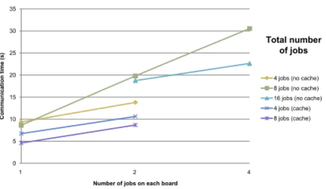
We presented some representative results concerning computation and com-munication times on figures 8 to 10. Figure 8 shows a dramatic increase of communication time when we put more jobs on the same board. This is because of the shared memory, offering a single access at once. Since the application is single program multiple data, all processes on the same boards need to access the memory at the same time, leading to congestion. Figure
0 5 10 15 20 25 30 35 1 2 4 Co mm u n ica tion t ime ( s)
Number of jobs on each board
4 jobs (no cache) 8 jobs (no cache) 16 jobs (no cache) 4 jobs (cache) 8 jobs (cache)
Total number of jobs
Figure 8: Communication time versus number of jobs on each board.
9 shows the correct general behavior, namely computation time drops ac-cording to the total number of jobs on each board. On this figure, we see that the number of jobs per board only has little impact on computation time, curves for 1 and 2 jobs per board being quite layered. Nevertheless, passing to 4 jobs per board begins to have a sensitive impact due to concur-rent memory accesses. Figure 10 reveals that, if the other criteria remain
0 25 50 75 100 125 150 175 200 4 8 16 32 Co mp u tatio n t ime ( s)
Total number of jobs
4 jobs / board (no cache) 2 jobs / board (no cache) 1 job / board (no cache) 2 jobs / board (cache) 1 job / board (cache)
Number of jobs on each board
Figure 9: Computing time versus the total number of boards.
stable, the number of jobs per board leads to an increase of total time. Memory is thus a bottleneck issue, obliging us to reconsider the SMP char-acteristic of our platform.
Nevertheless, the other characteristics of our platform would not seem to be a problem as we were able to reproduce a HPC-like behavior with multiple nodes. These results allowed us to continue our investigations by building a
0 20 40 60 80 100 120 140 160 180 200 1 2 4 Bench r u n t ime (s)
Number of jobs on each board
4 jobs (no cache) 8 jobs (no cache) 16 jobs (no cache) 4 jobs (cache) 8 jobs (cache)
Total number of jobs
Figure 10: Total time versus number of jobs per board.
second platform, even if the memory model needs to be reexamined.
4.2. Hardware Stream Dynamic Platform
The second platform focuses on the hardware virtualization flow, thus it integrates dynamic reconfiguration.
4.2.1. Overview
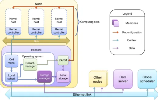
In order to simplify implementation, we only use hardware computing cells in that implementation. As a consequence, and since IPs used to eval-uate the platform do not make use of MPI, this platform does not need to implement it. Nevertheless, MPI will be present in the final version of the SPORE platform. HSDP is thus not HPC-oriented; rather it is dataflow-oriented. Figure 11 presents the HSDP design.
To handle dynamic hardware, we use a software reconfiguration manager able to send orders to a FaRM IP through a Linux driver. Bitstreams are stored, along with other application elements, on the data server. The stor-age manstor-ager transfers it to the local storstor-age when needed, in order to make it accessible by FaRM. SHP’s MPI server is replaced by a scheduler dispatch-ing work amongst nodes, where a local scheduler dispatches work amongst cells. To replace the shared memory-only communication used in SHP, we allow communication to be done directly through a bus. Implementation is done, as for SHP, on Xilinx’s ml507 development boards.
Computing cells are split in two parts: a static one and a dynamic one. The dynamic part, called kernel host, is configured using partial bitstreams. The static part, namely the kernel controller, is responsible for isolating the bus from the kernel host during the reconfiguration process. It also manages the
Node Host cell Operating system Data server Ethernet link Bus Reconf. manager Local storage Storage manager FARM Cell mana. Computing cells Kernel host Kernel controller Kernel host Kernel controller Kernel host Kernel controller Legend Memories Reconfiguration Control Data Other nodes Global scheduler Local sched.
Figure 11: View of HSDP system.
reset signal for threads. In any other case, it is invisible to the bus, giving direct access to the IPs’ registers.
The local scheduler is the entry point of the virtualization process for each node. It receives a job descriptor which will be parsed, extracting informa-tion about kernels. Then, the local scheduler advises the storage manager to grab needed files such as kernel descriptors, bitstreams, etc.
The storage manager is in charge of the “cache” management for bitstreams. Since the bitstream repository has a limited storage capacity, a least recently used policy is deployed when there is a need to store a new bitstream. Re-sources occupation for node components is given in table 2. Note that the kernel host’s resources are always monopolized, even if there is no IP mapped on, or if the IP has a smaller actual occupation.
4.2.2. Platform evaluation
As this implementation is dataflow-oriented, we chose a test applica-tion in which a kernel’s output is another kernel’s input, rather than a communication-oriented evaluation program such as NPB IS. The flow was evaluated using an AES encoding/decoding chain. The application has two parallel branches, each one encoding an input file, then decoding it. We
Table 2: Resources used by the HSDP components (percentages expressed on Virtex 5 fx70t global resources).
Resource Host cell Kernel Kernel host
occupation controller
LUTs 12,477 (27.9%) 290 (0.6%) 3,840 (8.6%)
BRAMs 42 (28.4%) 0 (0.0%) 0 (0.0%)
DSP48Es 13 (10.0%) 0 (0.0%) 0 (0.0%)
write a job descriptor containing this application. IP behavior is controlled by writing a thread access descriptor, and the characteristics of each IP are given using a kernel descriptor. All these files are written in XML using a specific syntax. As an example, the listing in figure 12 details the thread access descriptor containing the action sets used to access both encoder and decoder IPs. Some actions are constant writes to IP registers, while the cypher key is a reference to an input file. This makes it possible to change this key without changing the thread access descriptor, which is supposed to depend only on the kernel implementation.
<Thread_access_descriptor ID="12"Name="AES encoder and decoder thread access descriptor">
<Context>
<Restore>
<!--Connect IP-->
<ActionType="Register" Direction="Write"Data_constant="01" Offset="0" Size="4"/>
<!--Enable reset-->
<ActionType="Register" Direction="Write"Data_constant="03" Offset="0" Size="4"/>
<!--Diable reset-->
<ActionType="Register" Direction="Write"Data_constant="01" Offset="0" Size="4"/>
<!--Cypher key-->
<ActionType="Memory" Direction="Write"Data_reference="0" Offset="36"Size="4" Count="4"/>
<!--Disable premption-->
<ActionType="Register" Direction="Write"Data_constant="00" Offset="4" Size="4"/>
</Restore>
</Context>
<Behavior>
<Start>
<ActionType="Register" Direction="Write"Data_constant="01" Offset="20"Size="4"/>
</Start>
</Behavior>
</Thread_access_descriptor>
Figure 12: Thread access descriptor for AES IPs.
Implementing the AES encoder involves using 2430 LUTs (63.3% of the ker-nel host capacity), while the AES decoder uses 2975 LUTs (77.5%). The architecture layout can be seen on figure 13, with two computing cells and the PowerPC being the host cell base. Computing cell 0 is shown imple-menting an AES encoder while computing cell 1 hosts an AES decoder. Chain output data is recovered, as well as intermediate data at the encoder
Computing cell 1 PowerPC Computing
cell 0
Figure 13: Virtex 5 fx70t layout of HSDP implementation.
output, in order to check the accuracy of the process. The test has been conducted using a dual-cell and a single-cell platform, leading to different congestions in reconfiguration. On the dual-cell platform, both branches of the program can run independently. On the single-cell platform, only one thread can run at once, the second branch being in a waiting state until cell is clear. General results reveal that our design flow is correct since the obtained results are in line with expectations.
The application has been tested using compressed and uncompressed bit-streams, and the reconfiguration times have been measured and are given in table 3.
Table 3: Reconfiguration times expressed in clock cycles.
Compression Encoder Decoder
Enabled 79,633 91,232
5. Future work
HSDP implementation of SPORE is still being evaluated, using longer chains which are more representative of actual applications, in order to iden-tify potential flaws. Time measures concerning IP run time and reconfigu-ration overhead will also be conducted.
A third implementation of SPORE is planned in order to implement the complete flow, namely integrating both the reconfigurable behavior and the MPI capability. Given that it would be final platform, all elements of our theory should be present, including the hybrid nature of cells and kernel implementations, which can either be hardware or software. This platform would then gather the features of the previous two platforms, but with improvements to resolve the shortcomings revealed by these versions. This platform, whose current name is Hybrid HPRC & Stream Platform (HHSP), will adopt the manycore topology, managing communication through a NoC in order to overcome the SMP issues.
6. Conclusion
In this paper, we explained the notion of hardware/software online code-sign. With online codesign, we no longer need to consider the actual im-plementation of the kernels when at the design stage. Moreover, with this approach, we handle hardware and software implementation in one single movement. Thus, some or all of the kernels can have both implementations, the final one being chosen at run time.
This paper also presented a virtualization mechanism used to manage these kernels automatically in relation with their actual implementation, which may not be known before running. This mechanism defines ways to deal with a kernel implementation such as starting, setting parameters, etc. us-ing lists of actions to be carried out sequentially on the kernel.
Finally, we presented the SPORE platform and its various implementations, intended to be a demonstrator for our implementation flow. The various current and future SPORE implementations give us an opportunity to im-prove design flow with a real implementation highlighting potential issues we didn’t seen at design time.
This global flow allows execution of auto-adaptive applications, in which the used and unused resources are unpredictable and depends on the environ-ment. This behavior, where hardware or software nature of an application kernels can be decided at runtime, allows more flexibility than the offline
codesign used in most of the current platforms. As an example, a HPRC application, where hardware routines are statically defined, can run on only one kind of platform, and would need to be adjusted before it could be run on another platform. In this case, our virtualization flow, thanks to which we can disregard the underlying structure when designing the application, would allow us to run a given application on any platform able to implement this flow.
Bibliography
[1] AADL website, http://www.aadl.info, 2011.
[2] Æther project website, http://www.aether-ist.org, 2006.
[3] K. Asanovic, R. Bodik, B.C. Catanzaro, J.J. Gebis, P. Husbands, et al., The landscape of parallel computing research: a view from Berke-ley, Technical Report UCB/EECS-2006-183, Electrical Engineering and Computer Sciences, University of California at Berkeley, 2006.
[4] D. Bailey, E. Barszcz, J. Barton, D. Browning, R. Carter, et al., The NAS Parallel Benchmarks, http://www.nas.nasa.gov/News/ Techreports/1994/PDF/RNR-94-007.pdf, 1994.
[5] L. Benini, G.D. Micheli, Networks on Chips: A new SoC paradigm, Computer 35 (2002) 70–78.
[6] Y. Birk, E. Fiksman, Dynamic reconfiguration architectures for multi-context FPGAs, Comput. Electr. eng. 35 (2009) 878–903.
[7] Buildroot project website, http://buildroot.uclibc.org, 2011.
[8] J.A. Casas, J.M. Moreno, J. Madrenas, J. Cabestany, A novel hardware architecture for self-adaptive systems, in: AHS ’07: Proceedings of the Second NASA/ESA Conference on Adaptive Hardware and Systems, IEEE Computer Society, Washington, DC, USA, 2007, pp. 592–599. [9] F. Catthoor, N.D. Dutt, C.E. Kozyrakis, How to solve the current
mem-ory access and data transfer bottlenecks: at the processor architecture or at the compiler level, in: Proceedings of the conference on Design, automation and test in Europe, DATE ’00, ACM, New York, NY, USA, 2000, pp. 426–435.
[10] R. Chandra, L. Dagum, D. Kohr, D. Maydan, J. McDonald, R. Menon, Parallel programming in OpenMP, Morgan Kaufmann Publishers Inc., San Francisco, CA, USA, 2001.
[11] M.O. Cheema, O. Hammami, Application-specific SIMD synthesis for reconfigurable architectures, Microprocessors and Microsystems 30 (2006) 398 – 412. Special Issue on FPGA’s.
[12] J. Crenne, P. Bomel, G. Gogniat, J.P. Diguet, End-to-end bitstreams repository hierarchy for FPGA partially reconfigurable systems, in: G. Gogniat, D. Milojevic, A. Morawiec, A. Erdogan (Eds.), Algorithm-Architecture Matching for Signal and Image Processing, volume 73 of
Lecture Notes in Electrical Engineering, Springer, 2011, pp. 171–194.
[13] J.J. Dongarra, P. Luszczek, A. Petitet, The LINPACK benchmark: past, present and future, Concurrency and Computation: Practice and Experience 15 (2003) 803–820.
[14] F. Duhem, F. Muller, P. Lorenzini, FaRM: Fast reconfiguration man-ager for reducing reconfiguration time overhead on FPGA, in: 7th In-ternational Symposium on Applied Reconfigurable Computing (ARC 2011), Belfast, United Kingdom.
[15] E. El-Araby, I. Gonzalez, T. El-Ghazawi, Exploiting partial runtime reconfiguration for High-Performance Reconfigurable Computing, ACM Trans. Reconfigurable Technol. Syst. 1 (2009) 21:1–21:23.
[16] T. El-Ghazawi, E. El-Araby, M. Huang, K. Gaj, V. Kindratenko, D. Buell, The promise of High-Performance Reconfigurable Comput-ing, Computer 41 (2008) 69–76.
[17] M. El Khodary, J.P. Diguet, G. Gogniat, F. Muller, M. Auguin, On simulating operating environment decisions in a sane network, in: 2nd ÆTHER - MORPHEUS Workshop- Autumn School From Reconfig-urable to Self - Adaptive Computing (IST AMWAS 08), Lugano, Switzerland.
[18] R. Ferrer, J. Planas, P. Bellens, A. Duran, M. Gonzalez, X. Martorell, R. Badia, E. Ayguade, J. Labarta, Optimizing the exploitation of mul-ticore processors and gpus with OpenMP and OpenCL, in: K. Cooper, J. Mellor-Crummey, V. Sarkar (Eds.), Languages and Compilers for Parallel Computing, volume 6548 of Lecture Notes in Computer
[19] C. Foucher, F. Muller, A. Giulieri, Exploring FPGAs capability to host a HPC design, in: 28th Norchip Conference (Norchip 2010), Tampere Finland, pp. 1–4.
[20] A. Gothandaraman, G.D. Peterson, G.L. Warren, R.J. Hinde, R.J. Har-rison, FPGA acceleration of a quantum monte carlo application, Par-allel Comput. 34 (2008) 278–291.
[21] W. Gropp, E. Lusk, N. Doss, A. Skjellum, A high-performance, portable implementation of the MPI message passing interface standard, Parallel Comput. 22 (1996) 789–828.
[22] G. Hager, G. Wellein, Architecture and performance characteristics of modern High Performance Computers, in: H. Fehske, R. Schneider, A. Weie (Eds.), Computational Many-Particle Physics, volume 739 of
Lecture Notes in Physics, Springer Berlin / Heidelberg, 2008, pp. 681–
730.
[23] R. Hempel, D.W. Walker, The emergence of the MPI message passing standard for parallel computing, Comput. Stand. Interfaces 21 (1999) 51–62.
[24] M.D. Hill, M.R. Marty, Amdahl’s law in the multicore era, Computer 41 (2008) 33–38.
[25] J.P. Hoeflinger, B.R. De Supinski, The OpenMP memory model, in: Proceedings of the 2005 and 2006 international conference on OpenMP shared memory parallel programming, IWOMP’05/IWOMP’06, Springer-Verlag, Berlin, Heidelberg, 2008, pp. 167–177.
[26] H.P. Hofstee, Power efficient processor architecture and the Cell proces-sor, in: HPCA ’05: Proceedings of the 11th International Symposium on High-Performance Computer Architecture, IEEE Computer Society, Washington, DC, USA, 2005, pp. 258–262.
[27] J. Howard, S. Dighe, Y. Hoskote, S. Vangal, D. Finan, et al., A 48-core IA-32 message-passing processor with DVFS in 45nm CMOS, IEEE International Solid-State Circuits Conference (2010).
[28] Intel Labs., SCC External Architecture Specification, http://techresearch.intel.com/spaw2/uploads/files/SCC EAS.pdf, 2010.
[29] R.A. Iushchenko, Measuring the performance of parallel computers with distributed memory, Cybernetics and Sys. Anal. 45 (2009) 941–951. [30] S. Kestur, J.D. Davis, O. Williams, Blas comparison on fpga, cpu and
gpu, in: Proceedings of the 2010 IEEE Annual Symposium on VLSI, ISVLSI ’10, IEEE Computer Society, Washington, DC, USA, 2010, pp. 288–293.
[31] P. Kjeldsberg, F. Catthoor, S. Verdoolaege, M. Palkovic, A. Vandecap-pelle, Q. Hu, E. Aas, Guidance of loop ordering for reduced memory usage in signal processing applications, Journal of Signal Processing Systems 53 (2008) 301–321.
[32] P. Kwan, C. Clarke, FPGAs for improved energy efficiency in processor based systems, in: T. Srikanthan, J. Xue, C.H. Chang (Eds.), Advances in Computer Systems Architecture, volume 3740 of Lecture Notes in
Computer Science, Springer Berlin / Heidelberg, 2005, pp. 440–449.
[33] P. Marquet, S. Duquennoy, S. Le Beux, S. Meftali, J.L. Dekeyser, Mas-sively parallel processing on a chip, in: Proceedings of the 4th inter-national conference on Computing frontiers, CF ’07, ACM, New York, NY, USA, 2007, pp. 277–286.
[34] MPICH2 website, http://www.mcs.anl.gov/research/projects/mpich2, 2011.
[35] F. Muhammad, F. Muller, M. Auguin, Dynamic and self adaptive re-source management: æther operating environment, in: 3rd IEEE Int. Conference on Emerging Technologies, Islamabad.
[36] J. Nickolls, I. Buck, M. Garland, K. Skadron, Scalable parallel program-ming with CUDA, in: ACM SIGGRAPH 2008 classes, SIGGRAPH ’08, ACM, New York, NY, USA, 2008, pp. 16:1–16:14.
[37] OpenCL official website, http://www.khronos.org/opencl, 2011. [38] Y. Oyanagi, Future of supercomputing, Journal of Computational and
Applied Mathematics 149 (2002) 147–153.
[39] D.B. Skillicorn, D. Talia, Models and languages for parallel computa-tion, ACM Comput. Surv. 30 (1998) 123–169.
[41] P. Thoman, K. Kofler, H. Studt, J. Thomson, T. Fahringer, Automatic OpenCL device characterization: Guiding optimized kernel design, in: E. Jeannot, R. Namyst, J. Roman (Eds.), Euro-Par 2011 Parallel Pro-cessing, volume 6853 of Lecture Notes in Computer Science, Springer Berlin / Heidelberg, 2011, pp. 438–452.
[42] UML profile for MARTE, http://omgmarte.org, 2011.
[43] Unified Modeling Language website, http://www.uml.org, 2011. [44] D.H. Woo, H.H.S. Lee, Extending Amdahl’s law for energy-efficient
computing in the many-core era, Computer 41 (2008) 24–31.
[45] Xilinx, Inc., Xilinx Virtex 5 family, http://www.xilinx.com/support/ documentation/data sheets/ds100.pdf, 2009.
[46] Xilinx, Inc., Partial Reconfiguration User Guide,
http://www.xilinx.com/support/documentation/sw manuals/ xilinx12 3/ug702.pdf, 2010.
[47] Xilinx, Inc., Virtex-5 FPGA Configuration User Guide, http://www.xilinx.com/support/documentation/user guides/
ug191.pdf, 2010.
[48] Xilinx, Inc., Microblaze processor reference guide, http://www.xilinx.com/support/documentation/sw manuals/
xilinx13 2/mb ref guide.pdf, 2011.
[49] Xilinx, Inc., ml507 devlopment board user guide,
http://www.xilinx.com/support/documentation/boards and kits/ ug347.pdf, 2011.