HAL Id: lirmm-01904361
https://hal-lirmm.ccsd.cnrs.fr/lirmm-01904361
Submitted on 24 Oct 2018
HAL is a multi-disciplinary open access
archive for the deposit and dissemination of
sci-entific research documents, whether they are
pub-lished or not. The documents may come from
teaching and research institutions in France or
abroad, or from public or private research centers.
L’archive ouverte pluridisciplinaire HAL, est
destinée au dépôt et à la diffusion de documents
scientifiques de niveau recherche, publiés ou non,
émanant des établissements d’enseignement et de
recherche français ou étrangers, des laboratoires
publics ou privés.
Robotic mapping of a karst aquifer
Adrien Lasbouygues, Silvain Louis, Benoît Ropars, Luc Rossi, Herve Jourde,
Hélène Délas, Pierre Balordi, Rémi Bouchard, Mehdi Dighouth, Marc
Dugrenot, et al.
To cite this version:
Adrien Lasbouygues, Silvain Louis, Benoît Ropars, Luc Rossi, Herve Jourde, et al.. Robotic mapping
of a karst aquifer. IFAC: International Federation of Automatic Control, Jul 2017, Toulouse, France.
�lirmm-01904361�
Robotic mapping of a karst aquifer ⋆
Adrien LASBOUYGUES∗ Silvain LOUIS∗ Benoit ROPARS∗∗ Luc ROSSI∗∗∗ Herv´e JOURDE∗∗∗∗
H´el`ene DELAS† Pedro BALORDI† R´emi BOUCHARD†
Mehdi DIGHOUTH† Manu DUGRENOT†
Eric JACQUEMIN† Frank VASSEUR† Lionel LAPIERRE∗
David ANDREU∗
∗LIRMM, University of Montpellier, 860 rue de St Priest, 34080
Montpellier France (e-mail: [email protected]).
∗∗REEDS, 860 rue de St Priest, 34080 Montpellier France ∗∗∗Syera, Quartier des Bl´eton`edes, 83210 Belgentier France ∗∗∗∗HydroSciences Montpellier, University of Montpellier, 300, avenue
du Professeur Emile Jeanbrau, 34090 Montpellier France.
†Plong´eeSout
Abstract: Karst aquifers are one of the main sources of groundwater in the world. However, sustainable exploitation of these resources requires to gather knowledge about these highly complex environments. Robots can thus be used to explore the source and gather data about its structure as well as water quality. We here present results of our first experiment which took place in the Gourneyras exsurgence where we used two prototype mapping systems.
Keywords: Underwater Robotics, Mapping Systems, Environment Exploration, Marine
Systems, Unstructured Environments 1. INTRODUCTION
Karst aquifers represent the main access point from which resources contained in underground reservoirs can be ex-ploited. It is thus a major freshwater source especially in areas, such as the karstic Mediterranean Basin, where water is a scarce resource. However, these groundwaters are widely underexploited [D¨orfliger et al. (2008)] while they represent major economical and societal stakes. This is due to the complexity of karst aquifers. Indeed, because of their complex structure, the aquifers exhibit a very specific hydrodynamic behavior [Jourde et al. (2015)]. It is thus required to gather more data on their structure in order to get a better understanding of the behavior of the aquifers and promote the sustainable exploitation of their water resources. However traditional mapping techniques can only give limited information on the conduit structure (limited range and/or precision).
Remotely Operated Vehicles (ROVs) and Autonomous Underwater Vehicles (AUVs) thus become increasingly expected tools to carry on the mapping and exploitation of water resources contained within the aquifers and espe-cially to explore the deepest parts of the conduits network [Bakalowicz (2005)].
In this context we present two mapping systems devel-opped by our team. The first one is a mapping system, developed with the Syera company, that can be embedded on the divers’ underwater scooter to allow them to gather
⋆ The authors would like to thank the French Labex NUMEV for supporting this research under grant number ANR-10-LABX-20.
data in a much more efficient way than what is performed today. We have also tested our Ulysse ROV, prototype of a robotic system aimed at exploring confined environments. In this paper, we present the results of the first experiment aimed at testing those two systems. It took place on July 13th
and 14th
2016 in the Gourneyras aquifer in France, in collaboration with a team from the cave divers association Plong´eeSout.
These experiments had three main objectives.
• To demonstrate the relevance of both systems for mapping aquifer networks.
• To illustrate all the challenges that must be faced in order to design a system suitable for long-range aquifer exploration.
• To gather on-the-field data which will be used to assess the relevance of the proposed solutions to the identified issues.
2. SYSTEMS PRESENTATION
In this section, we present the two systems tested during this experiment.
2.1 The Ulysse ROV
The Ulysse ROV is the first prototype of confined environ-ments exploration robot developped at LIRMM (Figure 1). It has been designed with the objective to have as a simple logistics as possible. Indeed, light logistics is a key criterion to allow an efficient use of our systems within our applicative context.
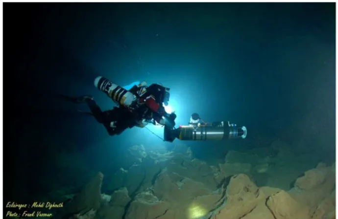
Fig. 1. The Ulysse ROV during the mission. (Photo Credits : Frank Vasseur)
The Ulysse is a 12 thrusters, 6 Degrees of Freedom (DoF) ROV. Its dimensions are 41 x 54 x 68 cm (width, length and height respectively) and its dry mass is 45 kg. It is constituted of two identical actuation stages connected to-gether and embeds its own energy storage for an autonomy of 2 hours. The ROV is connected to the surface through a 80-meters long tether that only conveys data flux.
It embeds an Inertial Measurement Unit (IMU), a pressure sensor (to measure depth), an IP-camera, both internal and external temperature sensors as well as battery state and water intrusion sensors. Two additional sensors are used for the mapping. The first one is a Super Seaking profiling sonar1
. This sensor is used to detect and map the walls of aquifer for the model reconstruction and to avoid them during exploration. The second sensor is a SeaPILOT Doppler Velocity Log (DVL)2
which is used to measure robot speeds and thus reconstruct the trajectory of the robot.
The controller is splitted into two different parts. A Dropix3
serves as low level controller. It is in charge of managing the IMU, the pressure, temperature, battery state and water intrusion sensors, running basic control laws (such as attitude control) and sending commands to engine drives.
The Dropix communicates with a higher level controller which is a BeagleBone Black [Coley (2014)] over a serial line with Modbus protocol. The BeagleBone is in charge of running more complex control laws which may require additionnal sensors such as sonars. Since communication between the robot and the surface is performed through an
1 http://www.tritech.co.uk/media/products/ dual-frequency-profiler-super-seaking-dfp.pdf 2 http://rowetechinc.com/wp-content/uploads/2013/12/ LO-RES-SeaPILOT-300-600-1200-DVL-Brochure-27-Dec-2013.pdf 3
The Dropix is a French clone of the Pixhawk controller [Meier et al. (2015)].
ethernet link, the BeagleBone is also in charge of collecting user inputs, processing them if required and transferring the relevant commands to the Dropix. Finally, the Bea-gleBone gathers sensor measurements and execution data and transfer them to the surface control station where they are logged.
From the Software point of view, the system embeds all the latest developments made at LIRMM in the field of Underwater Robotics. It thus uses the dynamic dispatcher presented in Ropars et al. (2015) adapted for a 12-engines system. We also implement the wall avoidance control law presented in [Lasbouygues et al. (2014)]. Finally the Software architecture has been designed using the Atom Methodology [Lasbouygues et al. (2015)]. On the Dropix, we use the PX4 framework [Meier et al. (2015)] while a Xenomai 2.6 serves as Real-Time Operating System on the BeagleBone Black. The control architecture has been designed using the ContrACT Middelware [Passama and Andreu (2011)].
2.2 The Navscoot system
The second system we experimented is the Navscoot which is a mapping system that can be assembled on an under-water scooter (Figure 2).
Fig. 2. The Navscoot during the mission. (Photo Credits : Frank Vasseur)
The Navscoot embeds the same profiling sonar and the DVL than the Ulysse ROV. They are connected through an ethernet switch to a Raspberry Pi 3. Its role is to collect and time stamp data coming from sensors to store the information in dedicated files that can then be retrieved once the mission is complete. Relevant sensor data are also displayed on a navigation interface. The Navscoot is also equipped with a pressure sensor (to measure depth) and an external temperature sensor. Finally it is worth noting that attitude data are gathered from the attitude sensor integrated to the DVL.
The whole system is assembled on an aluminium frame which can be mounted on a Bonex Reference RS scooter4
. The assembled scooter is presented on Figure 3. It is worth noting that the DVL is oriented upwards.
4
Fig. 3. Overview of the Navscoot system. (Photo Credits : Pedro Balordi)
3. EXPERIMENTS AND RESULTS
Our tests lasted two days on July 13th and 14th 2016. We realized these experiments whith the support of Plong´eeSout, a cave divers association. Their role was to support our experiments by ensuring the safety of the robot, driving the Navscoot system and documenting our experiment. Beyond that, their contribution was also essential because they share with us their experience on karstic environments allowing us to have new hints on strategies that could be employed to deal with the nu-merous issued encountered during karstic exploration.
3.1 Experimental site
Our experiment took place in the Gourneyras exsurgence located near the village of Saint-Maurice-Navacelles lo-cated 60 kilometers north of Montpellier in the South of France. This site both presents galeries with the typical characteristics of karst aquifers such as chaotic rock for-mations or pile of collapsed stones and provides a good hint on the access conditions to this type of exsurgence. The entry vasque is located 60 meters below the access track. While people go down through a steep path, the equipment can be transferred using a stretcher.
In this context, our choice of developing a system requiring light logistics to be deployed proved relevant.
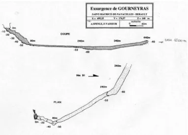
Figure 4 presents a topography of the aquifer. Over the first 80 meters, the galery reaches by step a depth of 48 meters. Then the aquifer opens on an horizontal galery on a length of 160 meters where it reaches a depth of 60 meters. Then the galery slightly turns and progressively reaches a depth of 40 meters. At this point the diver is located at 400 meters from the entrance.
3.2 Robot Experiment
The test of the Ulysse ROV consisted in a 30 minutes-long dive during which we mapped the first 30 meters of the aquifer. The exploration phase of the mission ran smoothly with no major issue. However, despite the fact that we could see some walls of the gallery, their chaotic structure did not allow us to easily locate in the aquifer. This underlines the need to develop dedication navigation methods in such complex environments.
During the return phase we experienced some difficulties typical of karst aquifers. Indeed the tether got stuck three times in rocks (Figure 5). However we had anticipated this issue and, prior to the mission, dispatched two divers who
Fig. 4. Topography proposed by A. Spenle and F. Vasseur in 1991.
could intervene if the tether got stuck. Finally, we managed to come back to the entry vasque.
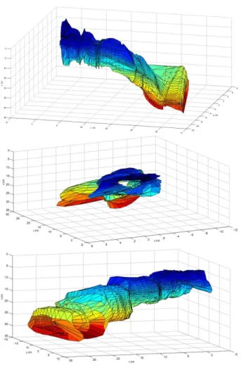
Fig. 5. The tether is making a loop. It is thus getting stuck around rocks. (Photo Credits : Mehdi Dighouth) The gathered data allowed to reconstruct a 3D model of the galery as shown in Figure 6. During the debrifing, both the diving team and our hydrogeologists partners gave us a very positive feedback concerning the quality of the gathered data.
3.3 Navscoot Experiment
For this experiment, a diver was to drive the scooter equipped with the Navscoot system through the galeries. It was decided that the entry galery (the first 80 meters roughly) which was partly scanned by the robot would be used to let divers get used to the handling of the system and take photographs of the system. Our aim was then to use the Navscoot in order to map the large horizontal galery that is located past this point.
The feedback of the divers on the system manoeuvrability is positive. The Navscoot system does not hinder the handling of the scooter. The divers only noticed that, as we could expect, the system has a higher inertia which requires the divers a small time to adapt and which also imposes them to turn with a more open angle. But, in the context of a mapping application, this last point is more an advantage than a weakness. Indeed, a smooth trajectory with rather open turns makes the 3D model reconstruction process easier.
Fig. 6. The 3D model reconstructed using measurements performed by the Ulysse ROV with different view-points.
Divers also praised the navigation interface on the system which displayed informations such as current heading or speed. Unfortunately, they could not test it on extended period of time. Indeed, after about 24 minutes of explo-ration, a defect in the cable connected to the profiling sonar caused a water entry into this cable. This caused a loss of the connection with the sensor and the logging program replaced the interface display by an error mes-sage.
However, we had gathered enough data to build a 3D model of the straight galery which is displayed on Figure 7. Again, both the divers and hydrogeologists gave us a very positive feedback over the model precision.
4. CONCLUSION
In this paper, we presented the results from a two-day experiment in the Gourneyras exsurgence. During this experiment, we tested two karst aquifer mapping systems, the Ulysse ROV and the Navscoot system.
These experiments allowed us to reach our objectives and to show that both systems were relevant to complete cur-rent mapping techniques. However, due to the complexity of the environment, we also demonstrated some limitations of our current ROV technology. But based on the difficul-ties encountered by previous explorations performed by
Fig. 7. The 3D model reconstructed using measurements performed by the Navscoot system with different viewpoints.
other robots, we expected to face some of those issues.
We will thus carry on the development of those systems, encouraged by the positive feedback from our partners, in order to overcome those limitations.
REFERENCES
Bakalowicz, M. (2005). Karst groudwater : a challenge for new ressources. Journal of Hydrogeology, 13: 148–160. Coley, G. (2014). BeagleBone Black System Reference
Manual - Revision C.1.
D¨orfliger, N., Jourde, H., Ladouche, B., Fleury, P., Lachas-sagne, P., Conroux, Y., Pistre, S., and Vestier, A. (2008). Active water management resources of karstic water catchment: the example of le lez spring. In World Water
Congress.
Jourde, H., Mazzilli, N., Lecoq, N., Arfib, B., and Bertin, D. (2015). KARSTMOD: A generic modular reservoir model dedicated to spring discharge modeling and hy-drodynamic analysis in karst. In B. Andreo, F. Carrasco, J.J. Durn, P. Jimnez, and J. LaMoreaux (eds.),
Hy-drogeological and Environmental Investigations in Karst Systems, 339–344. Springer Berlin Heidelberg.
Lasbouygues, A., Lapierre, L., Andreu, D., Hermoso, J.L., Jourde, H., and Ropars, B. (2014). Stable and reactive centering in conduits for karstic exploration. In
Lasbouygues, A., Ropars, B., Passama, R., Andreu, D., and Lapierre, L. (2015). Atoms based control of mo-bile robots with Hardware-in-the-Loop validation. In
Intelligent Robots and Systems (IROS 2015), IEEE In-ternational Conference on.
Meier, L., Honegger, D., and Pollefeys, M. (2015). PX4: A node-based multithreaded open source robotics frame-work for deeply embedded platforms. In Robotics and
Automation (ICRA), 2015 IEEE International Confer-ence on.
Passama, R. and Andreu, D. (2011). ContrACT: a soft-ware environment for developing control architecture. In 6th National Conference on Control Architectures of
Robots, Grenoble, France.
Ropars, B., Lasbouygues, A., Lapierre, L., and Andreu, D. (2015). Thrusters dead-zones compensation for the actuation system of an underwater vehicle. In European