Beyond analysis and representation in CAD:
a new computational approach to design education
By Maria Gabriela Caffarena Celani
M.Sc. in Architecture, University of Sio Paulo
Submitted to the Department of Architecture in partial fulfillment of the requirements for the degree of Doctor of Philosophy in the field of Architecture: Design & Computation at the Massachusetts Institute of Technology
September 2002
C 2002 Massachusetts Institute of Technology MASSACH NSTITUTE
All rights reserved.
--ACrT 1
8 2002
LIBRARIES
Signature of Author: Departnnt of Architecture,/$IIT 15 July 2002 Certified by: William J. Mitchell Professor of Architecture and Media Arts and Sciences School of Architecture and Planning, MIT Co-chair, Dissertation CommitteeTerr W. Knight Associate Idiofessor of Des n and omputation Department of Architecture, MIT Co-chair, Dissertation Committee
Accepted by:
Stanford Anderson, Profes'sor of History and Architecture Head of the Department, Department of Architecture, MIT Chair, Committee on Graduate Students
Document Services Room 14-0551 77 Massachusetts Avenue Cambridge, MA 02139 Ph: 617.253.2800 Email: docs@mit.edu http://libraries.mit.edu/docs
DISCLAIMER NOTICE
The accompanying media item for this thesis is available in the MIT Libraries or Institute Archives.
Dissertation Committee
Committee Co-Chairs
William J. Mitchell
Professor of Architecture and Media Arts and Sciences, School of Architecture and Planning, MIT
Terry W. Knight
Associate Professor of Design and Computation, Department of Architecture, MIT
Committee Members
George Stiny
Professor of Design and Computation, Department of Architecture, MIT Mitchel Resnick
Associate Professor,
Abstract
Thesis Co-supervisors William J. Mitchell Professor of Architecture and Media Arts and Sciences, School of Architecture and Planning, MIT Terry W. Knight Associate Professor of Design and Computation, Department of
Architecture, MIT
Beyond analysis and representation in CAD:
a new computational approach to design education By Maria Gabriela Caffarena Celani
Submitted to the Department of Architecture on July 15, 2002, in partial fulfillment of the requirements for the degree of Doctor of Philosophy in the field of Architecture: Design & Computation, at the Massachusetts Institute of Technology.
This thesis aims at changing students' attitude towards the use of computer-aided design (CAD) in architecture. It starts from the premise that CAD is used mostly for analysis and representation, and not as a real design aide, and that architecture students have a bias against learning computer programming. For this purpose, a prototypical instruction system that mixes computer-aided design and computational design theory was developed, based on a series of fundamental concepts that are common to both fields. This sys-tem was influenced by Mitchell's (1987) The Art of Computer Graphics Programming and Stiny's (1976) shape grammars. Despite being based on solid theoretical foundations, CAD has pro-gressively become an exclusively practical tool, since its origins in the 50's and 60's, while computational design theories have been mostly restricted to the academic circles. This thesis proposes an inversion in the present situation: the study of CAD theory, and the application of computational design into practice. The system pro-posed provides a conceptual framework that can be adapted to dif-ferent circumstances, including course formats and resources, as well as students' background and technical training. It is based on seven fundamental concepts from computational design theories that are also important to the study of shape grammars: symmetry, recursion, rule-based compositions, parameterization of shapes, generative systems, algorithmization of design procedures, and shape emergence. These concepts are introduced within a CAD context, where their practical implementation and experimentation are possible, focusing the understanding of the computational nature of design. During this research, the proposed system was tested in two case studies with students from schools that had con-trary orientations in terms of the importance of CAD in the archi-tectural curriculum. In these experimental courses, students' activi-ties evolved from using a commercial CAD tool in an innovative way, to the use of programming techniques for creating meaningful tools. Despite not having a statistical reach, the fieldwork allowed drawing preliminary conclusions about the proposed system's effi-cacy, since virtually all the students reported changing their under-standing of the role of CAD in architecture, while some also acknowledged a conceptual influence in other subjects and in the way they see architecture.
Acknowledgement of sponsors
I would like to express my special thanks to CNPq, the Brazilian
National Council for Scientific and Technologic Development, and to the Rosenblith Fund for their financial support.
Biography
Gabriela Celani, born (1967) and raised in Sio Paulo city, Brazil, holds a B.Arch. (1989) and an M.Sc. (1997) in Architecture and Planning from the School of Architecture and Planning of the University of Sio Paulo (FAU-USP). She taught at the University of the Paraiba Valley (UNIVAP), between 1993 and 1997, and worked as a research and teaching assistant at MIT for Professors William J. Mitchell, Terry W. Knight, Takehiko Nagakura and Michael Dennis from 1999 to 2001. She has also worked in archi-tectural practice for many years in Boston, Sio Paulo, Rio de Janeiro and Sio Jose dos Campos.
Acknowledgements
There are many people I would like to thank for their support and help during the years I spent at MIT, and when I was doing the field research in Brazil. Some of them are, in alphabetical order:
Ana Vera Macedo Wynne
Birgul Kolakoglu, Ph.D. graduate in Design & Computation Cynthia Wilkes, secretary of the Deans, School of Architecture and
Planning, MIT
Doris Kowaltowski, Professor of Architecture, FEC-UNICAMP Flivia McLaughlin
George Stiny, Professor of Design and Computation, Department of Architecture, MIT
Jack Valleli, Department of Architecture, MIT, Administrative Assistant
Joio Rocha, Ph.D. candidate in Design & Computation Jose Duarte, Ph.D. graduate in Design & Computation
Larry Sass, Ph. D. Assistant Professor, Department of Architecture, MIT
Marcelo Giacaglia, Professor of Architecture, FAU-USP
Maria Antonieta Celani, Professor of Applied Linguistics, PUCSP Maria Ruth Amaral Sampaio, Dean, FAU-USP
Miranda McGill, M.Sc. in Architecture, MIT
Mitchel Resnick, Associate Professor, Media Laboratory, MIT Rende Caso, Administrator of Academic Programs, Department of
Architecture, MIT,
Riusuke Naka, Professor of Architecture, MIYAGI University Roberto Okada, Professor of Information Technology, MIYAGI
University
Susan Yee, Ph.D. Research Scientist, Department of Architecture, MIT
Takehiko Nagakura, Professor of Architecture, Department of Architecture, MIT
All the staff at MIT
Very special thanks to Terry W. Knight for her tireless and diligent reading of all my writing, endless patience and continuous support, and to William J. Mitchell for his brilliant insights that encouraged me to join this Ph.D. program to begin with and guided me through this dissertation process. Very special thanks also to Mitchel Resnick, for making me see computers in education from a whole new perspective and for his thoughtful suggestions in the final text, and to George Stiny, for being a continuous source of inspiration and always encouraging me to think deeper.
I would also like to thank all the students at UNICAMP and FAU-USP who participated in the experimental courses, all of my fami-ly and friends for their support and patience, and my husband, Ba,
Contents
I. Introduction II. Background III. Methodology IV. Prototypical System V. Case studiesVI. Data analysis
I.a.CAD history
II.b.Computational Design
II.c.CAD in Brazilian architectural education II.d.Research questions
III.a.Research methods in this study III.b.Sources of secondary research III.c.Qualitative research
III.d.Case study versus experiments, survey and action research
III.e.Grounded theory III.f.Reliability and validity IV.a.Objectives
LV.b.A generic system
IV.c.Pedagogical issues
IV.d.Choosing concepts and examples IV.e.Symmetry
IV.f.Recursion IV.g.Design rules
IV.h.Parameterized shapes IV.i.Generative systems
IV.j.Algorithmization of design procedures IV.k.Emergent shapes
IV.l.Final discussion or project
V.a.Two instances of the prototypical system V.b.Pilot work
V.c.UNICAMP workshop
V.d.FAU-USP mini-course
VI.a.Data organization and presentation
VI.b.Initial attitude towards CAD (assumption) VI.c.Attitude towards programming
VI.d.Understanding design environments and tools VI.e.Understanding the concepts
Vl.f.Applying the concepts to architectural design VI.g.Attitude-change towards CAD
VI.h.External reach 25 51 61 85 111
Contents VII. Conclusions VIII. Bibliography IX. Appendix A X. Appendix B XI. Appedndix C XII. Appendix D XIII. Appendix E
VII.a.Confirmation of original assumptions VII.b.Answering the original research questions VII.c.Unexpected observations
VII.d.Critique
VII.e.Communication and Future work
Students' names and background Description of exercises
Excerpts from classroom journals Assessment questionnaires Accompanying CD-ROM 165 175 181 183 185 189 201
I.Introduction
"What is a man if he is not even honest? And also, what is an architect, if he is not even logical?" (Rogers, 1979 p.27)
Assumptions
This thesis starts with the assumption that there is currently a gen-eral misconceptioi about the application and utility of computers, in general, and computer-aided design (CAD) software, in particu-lar, in architecture. After a period of mystification, when some peo-ple believed -while others doubted -that it was possible to solve all the problems by pressing a key, CAD technology has been used mainly for representational purposes, both for drafting and for real-istic simulations. In other words, computer-aided design became computer-aided drafting.
There is evidence that the quick development of computer graphics and the popularization of computer hardware and software are some of the reasons that led to the present situation. As Mitchell
(1990b) puts it,
"The negative effect offourth-generation CAD was to establish a banal and simplistic conception of CAD functions and style of interaction in the minds of many architects.(..) The theoretical foundations of these systems [established a quarter of century
before] remained mostly unexamined, and the wider possibilities were largely ignored" (p.483)
Another assumption is that there is a bias against learning comput-er programming among architecture students, which often deprives them from having a higher control on the CAD tools they use. Finally, I also assume that most CAD software users do not have any knowledge about the origins of computer-aided design, which is another limitation to seeing applications of CAD that extend beyond pure representation and analysis.
At least two of the assumptions above were confirmed among the students who took part in the field-research experiments in this study. Because they all belonged to a particular country and region, it is impossible to generalize the assumptions to other cultures, but the results of the proposed system should be replicable in groups with similar characteristics.
I. Introduction
Definitions
The acronym CAD -meaning computer-aided design - is employed throughout this thesis as a synonym of the use of computer resources in the process of design in general, and particularly in architecture. Computer programs that aim specifically at helping designers are referred to as CAD software, which includes applica-tions for representation (drafting, 3D-modeling, rendering, rapid-prototyping, movie-making, etc.), analysis, simulation, optimiza-tion, shape exploraoptimiza-tion, alternative generaoptimiza-tion, and automation of design tasks.
The expression computational design is used to refer to any kind of generative process of design based on the use of computation, and thus a computational design theory is any design theory based on computations. The word computation, in turn, is used as a synonym of performing logical operations, not necessarily in the computer, and not exclusively with numbers or other symbols, but also with shapes and other forms of analogical representation.
Aims and objectives
This thesis aims at encouraging architecture students to see CAD as a "design partner" (Negroponte, 1975a), a means of "augmenting" the design process (Negroponte, 1975b), and to make a better use of the features in which the computer is effectively good at. Its objectives are:
1.To propose a prototypical instruction system in which CAD and computational design theories are intertwined, the first bringing the second into practice, and the second justifying the first;
2.To test the proposed system in a "real world" context;
3.To search for preliminary evidence of the proposed system's effi-cacy in changing students' attitude towards the use of CAD in architectural design.
In order to test the system, two experimental courses were taught in two different architecture schools in Brazil. The two instances of the system constitute the case studies explained in detail in the body of this dissertation.
With the present thesis, I hope to contribute to the field of comput-er-aided design by:
I. Introduction
1.Suggesting an approach to CAD instruction that takes into account its underlying theoretical principles and is not exclusively concerned with representation;
2.Demonstrating practical applications of computational design theories that have been relegated to theoretical studies or imple-mented with the use of advanced techniques that are out of the reach of the common architect or the undergraduate student.
Scope
It is often difficult to explain what a thesis is not about. The issues below emerged from some of the initial questions and expectations presented by students of the two experimental courses. This thesis
is not about:
1.Teaching programming, or the use of a particular CAD program or programming language;
2.Teaching design or a particular design methodology;
3.Presenting CAD and computational design techniques as the best or only way to design;
Although I have tried to be as inclusive as possible, the thesis also does not aim at showing all the possible applications of computa-tional design and CAD. The concepts introduced in the prototypi-cal system are without any doubt important ones in the underlying theoretical basis of CAD and computational design, but they cer-tainly do not exhaust relevant topics in the study of each.
On the contrary, this thesis aims at helping architecture students (and designers in general) to see new possibilities in the use of computers in design, and at informing which are some of these pos-sibilities, and how they can be applied with what they have at hand. Yet, the thesis does not imply that the quality of students' designs will be necessarily improved with the new approach to CAD edu-cation proposed (which is, of course, very desirable).
Personal background
In my first architecture internship, while still attending college, I was often given the task of developing different alternatives for the same design problem. Design problems varied from optimization problems, such as generating different parking lot layouts, to more
I. Introduction
Figure 1: Hand drawing,
1989.
Figure 2: One of my first
CAD models, 1989.
open-ended, creative problems, such as suggesting different forms for a light fixture.
In my first job as an architect, I often felt mind-numbed when I had to hand-draw construction documents of different versions of the same bathroom for different clients (at that time I only used CAD for 3D presentation models and walkthroughs). When I started using CAD for drafting on a daily basis, such tasks became easier, for it was possible to reuse some of the lines from one drawing to the next, but I knew there was much more that could be done with the computer.
A few years later, as a CAD instructor for undergraduate
architec-ture students, I had to focus on CAD software commands to fulfill students' needs. But at the same time I was already trying to give
CAD a higher status by using three-dimensional modeling to help
students visualize space while designing (that was the time of "vir-tual design environments"). Computer drafting and modeling soon became a prerequisite to some internships, but students found out that being experienced with CAD was not a synonym of making good architecture.
Digging out the history of CAD from its very origins, and getting in touch with computational design theories, I finally started seeing the connections between CAD software's geometric and generative principles and computational design theories. It is important, here, to make a clear distinction between "computational" and "comput-er-based" design. The former can -but does not necessarily need to
-make use of computers, which we will be doing here. The latter always implies the use of computers, but not necessarily of a putational theory of form. In other words, by simply using the com-puter to manipulate shapes we are not necessarily designing within a computational thinking.
The first ideas about developing a prototypical system proposing an integration between CAD, programming instruction, and a compu-tational study of form started in the [Northern Hemisphere's] win-ter of 2001, when I had the opportunity to co-teach a workshop on shape grammars with Professor Terry Knight and Miranda McGill (then an M.Sc. in Architecture student at MIT). The course focused on the use of computer applications for shape grammars, in a remote-collaborative design process between students at MIT and Miyagi University, in Japan (Celani, 2002). At that time, I realized
I. Introduction
Figure 3: By-hand shape grammar exercise in the Miyagi-MIT workshop.
Figure 4: The same type-of exercise developed with the help of a com-puter application. Miyagi-MIT workshop, by Carlos Barrios.
Figure 5: The art of com-puter graphics program-ming (Mitchell et al.,
1986).
how theoretical knowledge of computational design and technical training in CAD software and programming were complementary. Therefore, both are present in the instruction system developed here.
Sources of inspiration
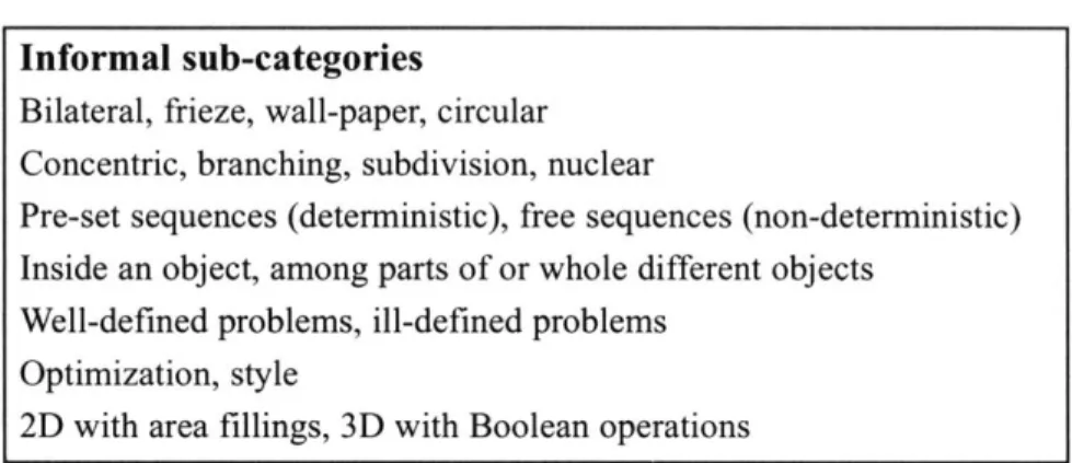
Obviously, I do not claim to be the first person to think about an instruction system mixing computer-aided design and computa-tional design theory. One of the pioneers of this approach was William Mitchell, one of my advisers. In his book with Ligget and Kvan (1987), Mitchell proposes a series of exercises using Pascal language, which are "as concerned with issues of design theory and visual aesthetics as [they] are with computer technology" (Mitchell, Ligget, & Kvan, 1987 p.vii). The art of computer graphics pro-gramming is a comprehensive book in terms of the technology it describes, but also very rich in beautifully illustrated architectural examples. Its conceptual exercises inspired me to propose the same kind of open-ended, interpretive questions that relate CAD pro-gramming to fundamental issues in design theory (and even to nature). As programming concepts are introduced, Mitchell pro-poses increasingly complex exercises on vocabularies of shapes, parameterized shapes, repetition, conditionals, hierarchical struc-tures and geometric transformations. Table 1 shows some examples of his exercises, categorized under those concepts.
The system developed here is based on the same basic concepts proposed by Mitchell, but grouped in a different way and with
dif-ferent objectives. Mitchell's concepts, in turn, are very close to those in Stiny's shape grammars theory, another important influ-ence to this thesis. Yet, unlike in Mitchell's book, the focus here is not on teaching programming, but rather on developing an under-standing of different applications of the computer in architectural design. Mitchell used Pascal, a plain programming language, while
I propose taking any CAD program that is at hand and using it in a
new way, by customizing and developing programs to automate its functions. In the case studies in this research, the CAD software used was Autodesk's AutoCAD, a popular program among archi-tects and schools, and the programming language, used sometimes like a script, was Visual Basic for application (VBA) edited in AutoCAD's own interactive development environment (VBAIDE).
My approach focuses on the rapid return on the time invested in
I. Introduction Concept Parameters Geeapkl 64 ~- "P7, Exercise
"Write a parameterized procedure to generate the basic vocabulary ele-ment [for the plan Mies of Van der Rohe's 'Brick Country House']. Use this in a program to replicate the plan. Then use it in a program to pro-duce variations on this theme" (p.198).
"It has often been argued that the aesthetic success of a composition is a matter of appropriate balance between 'unity' (which may be estab-lished by regular repetition) and 'variety' (which may be introduced by changing parameters from instance to instance). Test this proposition by generating repetitive compositions with different degrees of variation. Provide a critical analysis of your results" (p.250).
"Many town plans consist of regular street grids interrupted at various points. Examine some plans of this type. What are the conditions in which the grid is interrupted? Write a set of conditional rules that could be used to produce plans of this type, and discuss their effects" (p.321)
"All of the elements and subsystems of the Doric order have names.
Draw a tree diagram that depicts this hierarchy. Then write a program, structured in the same way, that generates the order" (p.3 51)
"Gothic tracery is often recursive. That is, a large pointed arch is sub-divided into smaller pointed arches, each of which is further subdivid-ed in the same way, and so on. Write a recursive procsubdivid-edure to generate such tracery designs" (p.353).
"The plan and elevation compositions of the modem architectural mas-ters Le Corbusier, Frank Lloyd Wright and Alvar Aalto rarely display rigid axial symmetry in the classical manner. But on careful inspection, they can usually be found to display less obvious symmetries and care-fully broken symmetries. Take a composition that interests you, and the exceptions and distortions that are used to break symmetry. Using the insights that you gain from this analysis, write a concise, expressive program to generate the composition" (p.476).
"Examine the leaves along a twig from a plant. Can you characterize the pattern that you see in terms of type and regular repetition? What changes from instance to instance? What kinds of arithmetic and geo-metric sequences are involved? Write a brief, illustrated analysis"
(p.250).
Table 1: Some examples of exercises proposed in "The Art of Computer Graphics Programming" (Mitchell et
I. Introduction
~>A
zi~
Figure 6: Shapes generat-ed by a shape grammar (Stinv. 1976).
learned, which I consider crucial to the success of the system, given the assumptions described above.
I also do not claim originality when suggesting the use of
pro-grammable CAD software with generative purposes. Other people have already thought about it, among whom are, for example, Takehiko Nagakura and Peter Testa, who teach applied computa-tional design courses at MIT. However, while their pragmatic approaches count on the technical and theoretical bases provided
by other graduate courses at MIT, mine explicitly introduces both
at the same time for the novice student.
Another thesis recently presented in this department (Yakeley, 2000) has also dealt with the question of CAD in architectural edu-cation, but with different objectives. While in that study program-ming was introduced as a way of helping students formalize their personal design methodology, here this formalization is considered as just one of the benefits of using CAD in the initial phases of design.
Parts of this thesis
This work is divided in seven sections:
1.In the Background section, I summarize the history of comput-er-aided design and introduce computational design concepts. I also comment on the current situation of the architectural curriculum in Brazil in terms of CAD and computational design, and ask
prelim-inary research questions.
2.In the Methodology section, I explain the research methods that have been used in the secondary research, field research and data analysis.
3.In the Prototypical system section, I develop an instruction sys-tem based on a series of concepts and corresponding exercises. The choice of such concepts is justified in the light of the shape gram-mar theory of design, and pedagogical characteristics of the pro-posed system are explained. In each sub-section, sample programs developed in VBA that illustrate the respective concepts are described (corresponding digital files can be found in the accom-panying CD-ROM).
4.In the Field research section, I describe the two instances of the prototypical system in practice and justify the choice of the course format in each case.
I. Introduction
5.In the Data analysis section, I present the results of the two experimental cases above and group the different types of data gathered according to categories.
6.Finally, in the Conclusions section, I draw some preliminary con-clusions based on the experimental courses described, preview pos-sible future consequences, and suggest further work in the area. 7.The Appendixes present the names of students who took part in the experimental courses, the instruments used for data collection, and excerpts from the classroom journals. The accompanying CD-ROM contains the web sites and course materials from each case-study course, with most of the exercises presented by students, as well as the VBA applications I have especially developed to illus-trate each of the prototypical system's concepts.
N~ N
tar, was able to make important bci iithi*4isrtation. Based on the
rasSUen
ti
Ddgsf .arugigir~mtudentaseb CAD mainly as adraft-ing-td, progsprninas, g, andignore the origins O towards the use of com-4 disis h dev4elop a prototypical CAD i~nrt -6a0computational i design approach, iithl-eta1.,1987)The Art of Computer a$,64atiy'sgi1976) shape grammars. The syttet a toW gib itecture students to see CAD as a deg -V i a n 1976a),and to make a better use of the features ine whipth-iotputer is effectively good at. Two s sl m Were: tested in different architecture shpdKIi og;4o kWnipreliminary conclusions about its efficacy.
II.Background
"All compositions of squares or of circles will be monotonous, and afford but
lit-tle pleasure, because the means whereby they are produced are very apparent. So we think that compositions distributed in equal lines or divisions will be less beautiful than those which require a higher mental effort to appreciate them"
(Jones, 2001, p.193).
II.a.CAD history
The development of CAD since its very origins to nowadays can-not be understood without looking at different fields evolving in parallel, but interconnected and affecting each other. For example, it is impossible to talk about CAD without citing the evolution of its practical medium, the computer. Computer Sciences, the theo-ries behind computer technology, have received influences from many other fields (Figure 7). For example, the Boolean Algebra formalism from the 19th century made it possible to develop bina-ry circuits; in the 1930's, British mathematician Alan Turing devel-oped the concepts needed for the design of the machines; later, John von Neumann developed the concept of storing both instructions and data in the computer's memory. CAD itself has also received influences from different fields. Operations Research, Cognitive Sciences and Artificial Intelligence affected the development of
CAD with "problem-solving" theory, wondering if the computer
could think, and igniting the development of intelligent CAD. Although it is impossible to exhaust the number of interconnections or fields affecting CAD, it is still important to take into account such influences to understand how it has been developed, taught and used in architecture.
Areas that have influenced CAD
Computer technology has influenced the development of CAD since the very beginning. Hardware technology has always been a major constraint to CAD, both in terms of processing capabilities, memory and storage, and in what concerns input and output devices. Mitchell (1977) summarizes the history of four genera-tions of computers from the 40's to the 70's. The very first, rudi-mentary electronic computer was developed with military purposes in the mid 40's. In the 50's, technical advances led to the first gen-eration of commercially marketed computers, with vacuum tube technology and low speed.
genera-II. Background
cognie architectural
cences opereoion
research
Figure 7: Fields influenc- I \
ing CAD. 'stooy_________________ rhtcua
tion of computers, from 59 to 65, with transistors and circuits assembled from independent components, allowing higher speed and the appearance of the first CAD systems; and a third genera-tion, from 65 to 71, with integrated circuits, allowing better per-formance and miniaturization. Time-sharing was another important development in the third generation, dramatically reducing costs by allowing computers to be used by different operators simultane-ously and opening the doors for the network concept.
The fourth generation of computers, starting in 71, was character-ized by the large scale integrated (LSI) silicon chip electronic cir-cuit technology. The large-scale IC (integrated circir-cuit) was devel-oped by Intel Corporation, which also introduced the memory IC, allowing the development of microcomputers and the computeriza-tion of small electronic equipment with standard components pro-grammed to do a specific job. The high demand for microproces-sors quickly reduced their cost, making their use possible in appli-cations for which electronic controls were too large and expensive before (such as automobiles and industrial robots), and promoting an even further miniaturization and cost reduction. This period made possible the widespread use of computers in science, engi-neering, and architecture, and coincided with the introduction of personal computers.
Since the early 80's, a fifth generation of computers has been char-acterized by very-large-scale integration (VLSI) technology (Phiri,
II. Background
r
Figure 8: Portable com-puter with VLSI
technol-ogy.
Table 2: Changes in com-puter technology, based
on Phiri (1999. n.6).
1999 p.10), substantially increasing the density of microprocessor
circuits. It made possible the mass production of personal comput-ers (not only for offices and univcomput-ersities, but also for schools and homes) and of different computerized, programmable devices, ranging from children's toys to automatic teller machines (ATMs). Another characteristic of this generation is the use of optical tech-nology, which has dramatically increased computers' capabilities of data storage and retrieval.
Table 2 partially shows Phiri's (1999, p.6) summary of the major changes in size, processing speed and memory capacity of comput-ers with different technologies.
It is possible to infer from the table that the performance of com-puters has increased at an incredible rate since its first develop-ment. The same happened in what concerns miniaturization. For example, while the first ICs from the 60's contained about 10 com-ponents on a silicon chip 3 millimeters square, by 1970 the number had grown to 1,000 on a chip the same size at no increased cost. By the mid-1990s, the larger microprocessors contained 20 million units on a chip less than two centimeters square. Since CAD demands a great processing power for geometric operations and lots of random-access memory (RAM) for the interactive display of the results, it is possible to infer how these changes have dramati-cally facilitated its development over the decades.
The introduction of extremely light but powerful portable comput-ers (laptops, notebooks and palms) and wireless communications technology since the early 90's has started to provoke new changes in CAD. Computers now can go to the building site, allowing archi-tects to make automatic updates to construction documents, where-as construction teams can keep up-to-date with the latest changes in the office. Especial versions of CAD have already been developed
Vacuum Transistor Integrated VLSI
tube circuitLSI
i Very large Mainframe Mini Micro
ropesi ig 10k 200k 5M 200M
vie4
M ~er 2K 32K 2M 250M
II. Background
Figure 9: Storage tube graphic display (Mitchell,
1977).
0000 MORNIN6O
PLEASXYV IM N YOUR SAME
WA.~F
THATS GREAT WARREN. BIT You DIDW. TELL MEYOU R SURNAME THAT I IME WHAT I5 i'
JULIAN THANK YOU.
YOUR NAME IS WARREN JULAN
DO , WARREN. WE ARE 000iTO DOA DEiON
I WILL DO THIE FIRST DION AND
THEN YOU CAN HAVE A 00 AT MODIFYINO TIE
0ESION TO TNER DIPROYE IT OR TO MEET
ADDITIONAL REQUIREMENTS THAT YOU.
PERHAP. DID' CONQWR IWITIALLY.
SY THE WAY I ROM THAT YOU DON'T WND
MY CALLiNG TOU WARREN.
WELL. I SUPPOME TO START WITH. YOU SHOULD
TULL ME WHAT TYPE OF ULDNO WE"EGOING
TO DESIGN A HOLSE
ML. NOW WE SMALL Er TO WORK ON WARREN JULIA"' HOUSE
NEFOXE WE START LET h TELL Yu WHAT YOU NEED TO KNOW.
YOU WILL PED TO KNOW WHAT ooMS OR
ARASAMERUIRED TO MAKE IP YOUR HOUSE.
THm APPROXIMATE ARAS THAT YOU WOULD
LIKE TO SEE THE ROOMSOCCUPY AND TWE
IMPORTANCE OF THE VARIOUS RELATIONSHIPE
ETWEEN ROOMW THE REILATIONSHIP..
I CALL THEM iNmmRAtCNS. .ARE NUMEERS
WHICH INDICATE THE IMPORTANCE OF ONE
ROOM OR AREA EEING ADJACENT TO
ANOTHER ROOM OR ARE.
NOW TED THIE DITERACOSOF TU
Emms LOUNGE ncHNU ASTH ocNo
FLEAER. NOW TWETN ITUDnBRACTIO
OPTEMUNWITUHIS
am0S LOUNGE KnCM MN 101040 GARAGE
052113 -4 000D! ROOM N. 1- 2 3 4 5 6 7 a I SEDROOSI E1410I-2 .ES .. SOSSE -3 ES 7 a : 2 3-4 LOUNGE 4 5S 0 4 412-p S KITCHEN I 22 4 0 41 I 4 Am 0 $ 1 4 . 4-1 7 000340 1 3 32Wno~ E OARA*E - -4 - - I-I-4 * EOYOUOETOCHANGOANY INIRACTUO? NOT AT TI ETAE
NOW WECOME TO DBCUSS THE AREAS
THAT YOU WOULD LKE TO SEEACHt
ROOM OCCUPY.
PREASEEVER YOUR ROOM AREAS IN THE
COMnM
IEVSH-Figure 10:
"Interaction in the Planning of Buildings" (Gero & Julian, 1975).
for such situations. In what concerns the future, with the incipient development of cluster computing, processing power will not be an issue any more. The use of remote computers in parallel distributed processing will soon become a commercial reality.
Although most input and output devices have influenced CAD, his-torically graphic displays have had a major effect in the interaction with the user. The very first CAD applications used little graphical interaction and performed mostly mathematical calculations or data management. With the development of graphic displays, CAD became more interactive and increasingly graphic-oriented.
At the beginning of CAD development, the unavailability of low-cost graphic displays was one of its major constraints. Until the 50's, interaction with computers had been done via punched cards and printouts. In the 50's and 60's, different kinds of vector, stroke or calligraphic displays were developed. The first commercially available displays were refreshed cathode ray tubes. They allowed smooth movement of graphics, but were very expensive and showed some flickering due to the need to constantly refresh the display. This kind of monitor could be used with a light pen for picking functions or drawing directly on the screen. In the mid 60's, storage cathode ray tubes eliminated the flickering, but were unable to represent a smooth movement of graphics (Mitchell, 1977). In the 70's, raster displays, based on inexpensive television tech-nology, "contributed more to the growth of the field than did any other technology" (Foley, van Dam, Feiner, Hughes & Phillips,
1977 p.8). In such displays, the buffer storage was made in terms
of pixels, whereas in the older vector displays instructions were needed to repeat the light strokes that produced the graphics. Nevertheless, smooth movement of graphics depended on extra memory (RAM), which was the only limitation to making raster displays the dominant technology. For this reason, vector displays were still used until the mid 80's, when the memory required by raster displays became affordable. Some of the advantages of raster displays over vector displays are lower cost and the possibility to display areas filled with solid colors or patterns. On the other hand, the major disadvantage of raster displays is the pixelation and jagged lines that occur during the conversion of vector coordinates into raster-scan mode. Nowadays, computer graphics is still con-cerned with anti-aliasing techniques.
II. Background
Figure 11: "In locco" CAD.
While interactive displays, with the use of light pens, were present in the 60's, at the very beginning of CAD development, with the introduction of the mouse and digitizers they were almost com-pletely forgotten. Yet, there has been a growing interest in the development of displays that allow easier interaction and simulta-neous use by more than one person. The MIT Media Laboratory has been researching applications for interfaces based on images pro-jected in the physical space rather than inside the monitor (Ishii,
1999). This trend will probably produce significant changes in CAD interaction in the short run.
In the same way that Computer Graphics is closely linked to the development of graphic displays, Computer Graphics and CAD are so intertwined that the definition of one sometimes overlaps the other. The major difference between them is that computer-aided design necessarily implies some kind of help from the computer in the design process (architectural design, in our case), even ifjust its graphic representation, whereas Computer Graphics is related to the synthesis of images in the computer, not necessarily for design purposes. In practice, the idea of CAD is generally linked to math-ematical models based on vectors, which can be rendered as raster images, and Computer Graphics includes necessarily raster images, based on pixels, although often using vector manipulation for their generation.
More recently, telecommunication technologies have influenced the development of applications in two main ways: by creating the possibility of remote collaboration and by dynamically feeding
CAD systems with on-line information from manufacturers. The
first trend has led to the development of remote collaborative CAD tools that allow users in different places to share drawings at the same time as they can see and talk (or chat) to each other. This tech-nology has made possible the development of big international teams of architects and consultants spread throughout the world, taking advantage of different local skills and in some cases even of the time difference to get projects finished on time. There are two types of applications in this category: some have the specific pur-pose of sharing information and promoting collaboration, while others were added to existing CAD tools, which now serve for both production and collaboration. A typical system of the first type includes real time whiteboard and chat, file sharing, conferencing, viewing and annotating raster images, vector drawings and 3D models. The second category adds to that a publish-to-web
func-11. Background
Figure 12: On-line
ing materials resou
tionality, using XML format to allow team members to drag-and-drop content directly to on-line files.
Another way in which the Internet has influenced CAD is by mak-ing available a huge amount of information from manufacturers. Many CAD applications now have Internet capabilities, being able to retrieve updated information from on-line catalogs, such as prod-build- uct specifications and symbol libraries. Even the CAD package Irces. itself can be updated through the Internet, by automatically having
new extensions delivered through subscription.
CAD development
Since the 60's, there have been two main fields of development in
CAD (Gero, 1994): (1) the "representation and production of the
geometry and topology of designed objects", related to Computer Graphics and sometimes accompanied by the automation of repeti-tive tasks; and (2) the "representation and use of knowledge to sup-port or carry the synthesis of designs" (p.vii), first with independ-ent, then with intelligent / support systems. While the first has seen widespread use in offices, reaching large publics through commer-cial programs, the latter has been usually restricted to experimental and specific applications. Those include generative systems and grammars, and knowledge-based systems.
Different facts in architectural theory and practice induced the sec-ond trend above, such as the Design Methods movement and pre-fabrication. The Design Methods movement of the 60's started with the translation of techniques from Operations Research into design. Although not exclusively concerned with computer-aided design,
CAD was among its points of interest, because it represented a
pos-sibility of dramatically changing the way design was performed. The Design Methods movement had four main purposes (Gregory
1971).
1.To design better, by understanding the design process, a purpose derived from the generalized dissatisfaction with the modern move-ment
2.To allow repetitive parts of the design process to be automated by the computer
3.To set up strategies for designers in new areas, such as industrial design
collab-II. Background
orate from the early stages, and allowing design to reach a higher level of complexity
In the search for understanding design better, the Design Methods movement was also influenced by the Cognitive Sciences, applying protocol analysis and rigid problem-solving techniques to system-atize design, and trying to reproduce human behavior in CAD sys-tems. The movement intended to use computers in all phases of design, from the conceptual phase, with the generation and evalua-tion of alternatives, to the more mundane producevalua-tion of building documents.
According to Negroponte (1975a), the influence of the Design Methods movement on CAD was extremely malignant, as it com-pletely eliminated intuition and established a rational trend in the development of CAD software, which still persists. This line of research continued even after the fading of the Design Methods movement. The application of CAD to design synthesis became itself a field in Artificial Intelligence and Pattern Recognition since
2 Select, from the outputs, the category of information that you require next
I PREFABRICATED STRATEGIES (Coiwergense)
1-1 Systematic Search (The Decision Theory Approach)
1-2 Value Analys 1-3 Systems Engineering 1-4 Mui.Machine System Designing; 1-5 Boundary Searching
1-6 Pep's Cumulative Strategy
1-7 CASA (Collaborative Strategy for Adaptable
Architcture)
2 STRATEGY CONTROL METHODS
2'1 Strategy Switching
2-2 Matche 's Fundamental Design Method (FDM)
3 Methods appropriate to your problem appear in the cells where te selected input rows arid output columns cross,
e.g. method 5-3 AIDA Is In input raw 4 and in output columnS. Methods ae listed below in order of their appearance in the book.
4 METHODS OF SEARCHING FOR IDEAS (Diergene
and Transformation)
4-1 Brainstorming 4-2 Synectics 4-3 Removing Mental Blocks 4-4 Morphological Charts
5 METHODS OF EXPLORING PROBLEM STRUCTURE
(Transformation)
5-1 interaction Matrix 5-2 Interaction Not
5-3 AIDA (Analysis of Interconnected Decision Area)
5-4 System Transformation S-5 Innovation by Boundary Shifting
5-6 Functional Innovation
5-7 Alexander's Method of Determining Components
6-8 Classification of Design Information
Figure 13: Methods for the different phases of the design process, suggested
by Jones (Jones, 1980).
3 METHODS OF EXPLORING DESIGN SITUATIONS
(Disge"n0)
3-1 Stating Objectives
3-2 Literature Searching
3-3 Searching for Visual Inconsistencies
3-4 Interviewing Users 3-5 Questionnabee
3.6 investigating User Behaviour 3-7 Systemic Testing
3-8 Selecting Scales of Measurement
3-9 Date Logging and Data Reduction
6 METHODS OF EVALUATION (Convergenmi 6-1 Checklists
6-2 Selecting Criteria 6-3 Ranking and Weighting 64 Specification Writing S'5 Quirk's Reliablity Index CHOOSING DESIGN METHODS
I Decide which of the inputa in
the chart is already known to you.
11. Background
Figure 14: Prefabricated construction.
Figure 15: Virtual
recon-struction of Palladio's Vila Sarego.
the late 70's, referred to as intelligent systems, and producing its own international conferences. In the 80's, the Design Thinking trend tried to lay down a theoretical basis for understanding design and developing CAD that was less rigid than before. The concept of local optimizations instead of an overall solution led to the automation of repetitive drafting tasks in the production of building documents, instead of attempting to control all phases.
Prefabrication is another architectural phenomenon that has influ-enced the development of CAD in the 60's. Although the system dramatically reduced the possibilities of design, this limitation was seen as an advantage in an "ill-defined problem" context, with the impossibility of the available computers to generate an endless design search space. Eastman (1975) points out that industrialized construction permitted greater integration between schematic designs and the production of building documents because all pos-sible details could be produced in advance. Despite being too spe-cific and limited, this was a very practical approach, and such sys-tems still have applications in the prefabricated building industry. However, with the use of CAD/CAM technology for producing building parts since the 70's, prefabrication is giving way to the manufacturing of custom-made parts that can be assembled
quick-ly and with great precision, eliminating the need to restrict designs
to a combinatorial problem.
In the same way that the Design Methods movement and the pre-fabricated building systems strongly influenced CAD in the 60's,
CAD has also influenced design and architectural education. For
example, the possibility of manipulating solids in virtual space, where they are not subject to the physical laws of impenetrability and gravity, has also influenced the conceptual phases of design. In fact, in what concerns architectural education, much importance has been given to the teaching of geometric modeling and its appli-cation in the design studio. Nevertheless, instead of what had been predicted, CAD did not replace by-hand drawings in terms of design method; it only replaced certain kinds of design representa-tions, such as the need for orthogonal views (Eastman, 1992). Rendering and animation packages made possible the production of sophisticated, photo-realistic images even in the early stages of the design process, but the impact of such representations has been stronger in the real-estate market and in the treatment of surfaces than in design concepts.
II. Background
CAD .software
-Com~ttt~r
fchutb~ogy-Z, -w
Table 3: Evolution of CAD and corresponding
developments in related fields. 63: Sketchpad Generation I CAD for Automobile and aerospace industries Transistors, mainframes, integrated cir-cuits, vector displays Time-sharing 68: 1st. "real time" system. 69:ARPA-NET 62:1st Methods con-ference, England. 68:1st Methods con-ference, USA. Computers introduced, with subjects offered by other depart-ments. Generation 2 Turnkey sys-tems, CAD for spatial planning & optimization 68-72: Arch. Machine Silicon cir-cuits, raster monitors, 16-bit minicom-puters,8-bit PC's Internet used to connect supercomput-ers in differ-ent universi-ties. 75: Shape Grammars 78: 1st. I.A. in CAD con-ference. First CAD specific courses. Generation 3 32-bit super-minis. Generation 4 Simplified for 16-bit PC's. Generation 5 Workstations. VLSI, minia-turization, 32-bit super-minis, graphic workstations, 16-/32-bit PC's, mouse + windows interface. 80: BITNET 88: NSFnet 89:CERN http 85: 1st. CAD Futures 85: 1st. ACA-DIA Computers in the studio. Emphasis in 3D modeling Generation 6 modeling, rendering, animation, special appli-cations. Generation 7 "do-it-your-self' CAD. Mobility, multimedia, laptops, palms, note-books. 92: First Web server 93:Mosaic 94:Netscape 95:Explorer 91: 1st. Design Thinking con-ference. Generation 8 Internet-based CAD, new interfaces. Cluster com-puting, active inter-faces. Internet influ-ences all aspects of life. Emphasis in advanced visualization techniques.
Seven generations of CAD
Mitchell (1990b) summarizes the progress of five generations of
CAD since the early 60's, to which I have added two more in the
90's and one more in the 2000's (see Table 3). Although the 50's had seen the birth of CAD at an experimental level, the first generation
II. Background
only started in the 60's. Ivan Sutherland's SKETCHPAD, presented as a doctoral thesis at MIT in 1963, is often cited as the very first interactive CAD system, which combined data-manipulation with graphic displays. Despite Sutherland's introduction of the concept of ill-specified, "loose" inputs, following developments had a dif-ferent orientation, eventually turning CAD into an overly precise tool (Negroponte, 1975a). The first large-scale CAD systems were developed for the automobile and aerospace industries. With com-mercial mainframes, tailored CAD applications were installed at a few architectural offices by the end of the decade. At that time,
CAD systems were operated by technicians and had little influence
in everyday life.
In the 70's, with more affordable 16-bit minicomputers, a second generation of commercially available CAD systems began. Those were expensive, turnkey systems, providing the hardware, soft-ware, installation, training, and technical support. These second-generation CAD systems were used in public construction with rep-etition in Britain, and by large engineering and architectural firms in the U.S., still operated mainly by technicians. Some layout pro-grams of this period aimed to completely eliminate drafting by automating the production of documents (Richens, 1992). Apart from the limitations imposed by the cost of computers, architects were still suspicious about the use of computers in design. According to Broadbent (1973), their attitude positions ranged from fear to mystification and resentment that computers would diminish humanity in architecture.
The 80's saw the parallel development of three different genera-tions of CAD, and an intention to realize its potential through new methodologies and practices (Kalay, 1987), such as architectural expert systems. Those were "rule-based and/or frame-based sys-tems that provided the means for codifying the problem-solving know-how of human-experts" (Schmitt, 1987 p.213). The third generation was a natural continuation of the previous two: with the new 32-bit super-minis, more large engineering and architectural firms acquired turnkey CAD systems. They were also introduced to some architecture schools, but still as a secondary activity.
At the same time, a fourth generation of simplified CAD was being developed to be used in the new 16-bit IBM and Apple Macintosh
Figure 16: Apple 11, personal computers, finally making CAD affordable to small firms
II. Background
-
L-Figure 17: Off the shelf, "do-it-yourself' CAD.
but were not powerful enough for CAD applications until the 80's. In 84, Apple introduced the mouse-and-windows style, to which Microsoft responded with the Windows operational system. The new interaction system has been responsible for the widespread acceptance of computers since then.
The simplification of CAD systems for personal computers pro-voked a radical change in the CAD culture, which Mitchell identi-fies as an inflection point in the history of architectural CAD, after which "the wider possibilities were largely ignored" (Mitchell
1990b p.483).
In fact, the new standardized, general-use CAD applications for PC's did not aim to help architects from the early, conceptual stages of design. Such specialized applications remained restricted to aca-demic research, while the great majority of offices kept the use of
CAD restricted to drafting and representation.
The fifth generation of CAD was related to the development of a new kind of computer in the 80's: the graphic workstation. For these machines, the developers of both mainframe and PC CAD adapted their products, at the same time as special applications were being developed. Graphic workstations were installed in medium and large firms, as well as in many architecture schools, sometimes combined with networks of PC's. Their 3D-modeling capabilities led to a discussion about the role of solids modeling in the design process and in the replacement of traditional bi-dimen-sional design representation (Eastman, 1987).
By the end of the decade, there was no substantial difference
between PC's and workstations both in price and in performance, giving rise to what can be perceived as a sixth generation of CAD. During the 90's, CAD became not only a pattern, but also a neces-sity in every architectural office, in the same way as word proces-sors completely substituted typewriters. CAD became a synonym of productivity. The introduction of 3D modeling, rendering and communication capabilities to the originally simplified PC CAD systems was made possible by the increasing power of micro-processors. As opposed to the first, standardized systems, the new ones had different levels of complexity and capabilities, as well as different prices, to fit specific areas, such as drafting, graphic-lay-out, modeling, rendering, and surveying (not to mention applica-tions out of the architectural scope, such as movie-making, GIS and
II. Background
project design).
Finally, still during the 90's, a seventh generation of do-it-yourself or home design CAD packages, destined to dwellers, rather than architects, has allowed users to design American style houses based on standardized building materials. Although limited, they offer much more freedom than the early pre-fabrication CAD systems
Figure 18: New inter- from the 70's. Those systems not only perform the structural analy-faces: H. Ishii's Cadcast sis of the wood frame and produce complete building documents (MIT Media Lab). based on standard details, ready for printing, but also make the
"designers" very proud of themselves.
In what concerns future developments, a clear direction is being taken towards web-based and wireless CAD that allow remote col-laboration and on-the-go work, which is a characteristic of the eight and last generation. Learning capabilities, which are already pres-ent in programs such as text editors, will also be incorporated to drawing editors. Another probable line of development relates to interactive interfaces. For example, data gloves have been used experimentally to transform spatial gestures in 3D meshes, and pro-jected displays are an alternative to monitors. As mentioned above, the MIT Media Laboratory's Tangible Interfaces has been working in this direction.
The drastic change in the primary objective of CAD from a prob-lem-solver to a drafting, representation and communication tool, but also a convenient medium to explore design ideas, probably has many reasons, which are related not only to technical and econom-ical questions, but also to philosopheconom-ical ones. One of these reasons could be the fact that each architect has a personal way of design-ing, and it would be extremely hard to develop a conceptual design system broad enough to fit every architect's personal methodology, or even to develop customizable enough tools that could be adapt-ed to each person. Another reason is that, over the years, CAD became increasingly complex, making it impossible for architects to develop their own applications. It takes large teams of software engineers, programmers, graphic designers, and sometimes archi-tects to developed a CAD system.
In these 40 years of CAD, what have we, architects, gained? Mitchell (1 990a) asserts that the advantages of computer-aided design over traditional drawings are "intelligibility, memory and structure" (p.5). On the other hand, he points out the difficulty in
II. Background ~t J Figure 19: Yufei's 3Dshaper: an example of a specially developed generative CAD applica-tion.
using CAD beyond representation, i.e., in design exploration, due to the computer's inability to recognize emergent shapes. As Negroponte (1975a) puts it, the reason for the failure of CAD as a design partner is the same as in the failure of automated translation programs: the lack of context:
"It is much easier to work on problem solving, decomposition, and if-then-because than to tamper with issues of learning and meaning
(..)" (p.38).
While truly helpful systems are not available, we can still try to use (and teach our students to use) the computer in the best way we can, taking advantage of what it is good at, and developing a critical atti-tude towards what the market offers in terms of software. Besides, we can re-introduce some design thinking, design generation and personal methodologies to a certain extent by customizing existing
CAD packages and producing our own little tools. As we saw,
sys-tems that aimed at completely automating the design process never reached widespread acceptance. That very fact probably explains more about how we design than any of such programs.
II.b.Computational Design
Nowadays, the word computational inevitably brings up the idea of something done with computers, but the machine is certainly not essential for computations to occur. So, if computational design is not necessarily a design made with the help of a computer, what is it? According to the Webster's New World Dictionary, calculating, a synonym of computing, can have three different meanings:
1. Tofind out by using mathematics (simple arithmetic in the case of
computing);
Traditionally, arithmetic - the science of numbers -has dealt with numbers. Yet, since design is typically expressed through shapes, analogical representations of buildings, computational design should also include the synthesis of form through shape computa-tion.
2. To find out by reasoning, to estimate;
In computational design, compositions should not be obvious, but organized according to some hidden logic that makes their
inter-II. Background
Figure 20: Symbolical representation of a beam.
Figure 21: Gaudi's
ana-logical representation of a structure.
Figure 22: Analogical representation of a plan.
pretation dependant on reasoning and inference.
3.To plan or intend.
Computational design should not happen by accident. A design algorithm, for example, is a carefully planned description of proce-dures. Similarly, a rule-based design, another type of computation-al design, may lead to surprising shapes as a result of intentioncomputation-ally defined rules.
Computation has been used in architecture in many different ways, that are exemplified in the following pages: in the synthesis of designs (generation), in their modeling (representation) and in their analysis (evaluation). This distinction could imply a design system in which solutions are generated, then represented, and finally test-ed, which is not my intention; the separation has been assumed just for practical reasons. The cases presented here do not attempt to exhaust the uses of computation in design, but to show some sig-nificant examples of its use in architecture.
Representation
Representation can happen as an independent art, but it is also a fundamental tool for synthesis and analysis. In most fields of sci-ence, since it is impossible to build or test directly the object of study, problem resolution is based on the use of models, with both analytical and synthetic purposes. Models are abstract representa-tions of real entities in a descriptive language, which can be ana-logical or symbolical. In architecture, drawings are an example of analogous representations, whereas force diagrams exemplify a
symbolical representation of the structural behavior of beams. The boundaries between representation and synthesis can some-times be very loose. For example, a generative system in design (synthesis) can be based on an algorithmic description (representa-tion) of shapes, where some values have been replaced by place-holders. When these placeholders or variables are replaced by
dif-ferent entities (such as numerical values or shapes) from a pre-delimited range of values or collection, the representation is com-pleted and a new design is created. Because representation is so tightly connected to synthesis, it is often impossible to prevent the influence of representation systems in design.


![Amplitude analysis of B[superscript +] →J/ψϕK[superscript +] decays](data:image/gif;base64,R0lGODlhAQABAIAAAP///wAAACH5BAEAAAAALAAAAAABAAEAAAICRAEAOw==)