Publisher’s version / Version de l'éditeur:
Vous avez des questions? Nous pouvons vous aider. Pour communiquer directement avec un auteur, consultez la première page de la revue dans laquelle son article a été publié afin de trouver ses coordonnées. Si vous n’arrivez pas à les repérer, communiquez avec nous à [email protected].
Questions? Contact the NRC Publications Archive team at
[email protected]. If you wish to email the authors directly, please see the first page of the publication for their contact information.
https://publications-cnrc.canada.ca/fra/droits
L’accès à ce site Web et l’utilisation de son contenu sont assujettis aux conditions présentées dans le site LISEZ CES CONDITIONS ATTENTIVEMENT AVANT D’UTILISER CE SITE WEB.
Conference: 2007 Northern Area Eastern Conference - Innovation in Corrosion Control [Proceedings], pp. 1-13, 2007-09-23
READ THESE TERMS AND CONDITIONS CAREFULLY BEFORE USING THIS WEBSITE.
https://nrc-publications.canada.ca/eng/copyright
NRC Publications Archive Record / Notice des Archives des publications du CNRC :
https://nrc-publications.canada.ca/eng/view/object/?id=103f1dc1-2823-45ca-a0f8-2944d3aaf1ef https://publications-cnrc.canada.ca/fra/voir/objet/?id=103f1dc1-2823-45ca-a0f8-2944d3aaf1ef
NRC Publications Archive
Archives des publications du CNRC
This publication could be one of several versions: author’s original, accepted manuscript or the publisher’s version. / La version de cette publication peut être l’une des suivantes : la version prépublication de l’auteur, la version acceptée du manuscrit ou la version de l’éditeur.
Access and use of this website and the material on it are subject to the Terms and Conditions set forth at New perspectives on electrochemical incompatibility of patch repairs of concrete structures
http://irc.nrc-cnrc.gc.ca
N e w p e r s p e c t i v e s o n e l e c t r o c h e m i c a l
i n c o m p a t i b i l i t y o f p a t c h r e p a i r s o f c o n c r e t e
s t r u c t u r e s
N R C C - 4 9 6 9 9
Z h a n g , J . ; Q i a n , S .
A version of this document is published in / Une version de ce document se trouve dans: 2007 Northern Area Eastern Conference, Ottawa, Ontario, Sept. 23-25, 2007, pp. 1-13
The material in this document is covered by the provisions of the Copyright Act, by Canadian laws, policies, regulations and international agreements. Such provisions serve to identify the information source and, in specific instances, to prohibit reproduction of materials without
written permission. For more information visit http://laws.justice.gc.ca/en/showtdm/cs/C-42
Les renseignements dans ce document sont protégés par la Loi sur le droit d'auteur, par les lois, les politiques et les règlements du Canada et des accords internationaux. Ces dispositions permettent d'identifier la source de l'information et, dans certains cas, d'interdire la copie de
NEW PERSPECTIVES ON ELECTROCHEMICAL INCOMPATIBILITY of PATCH REPAIRS OF CONCRETE STRUCTURES
Jieying Zhang1 and Shiyuan Qian2 Institute for Research in Construction
National Research Council Canada Ottawa, Canada, K1A 0R6
ABSTRACT
Patch repair is commonly used to rectify localized corrosion induced damage in concrete structures. However, inadequate durability in patch repair systems caused by new
corrosion attack is very common. The prevailing understanding of the corrosion
mechanism in patch repair is that the electrochemical incompatibility is the main reason for the initiation of macrocell corrosion between the patch area and substrate. This paper proposes new perspectives ton the concept of electrochemical incompatibility considering corrosion kinetics in patch repair systems. It is illustrated, by both electrochemical
principles and experimental verification, that although the incompatibility serves as the driving force for the macrocell corrosion, the corrosion rate depends more on the individual corrosion kinetics of the anode or cathode. It concluded that both macrocell and microcell corrosion mechanisms could play significant roles in the deterioration of patch repairs, and the total corrosion risk could be underestimated if the microcell corrosion mechanism is overlooked.
Keywords: Patch repair; Electrochemical Incompatibility; Corrosion; Macrocell; Microcell; Corrosion kinetics; Concrete Structures; Reinforcing Steel.
1
Research Officer, Tel 613-993-6752; Email: [email protected]
2
INTRODUCTION
Corrosion of steel in concrete is one of the most extensive durability problems that causes the degradation of concrete structures and raises concerns about structural safety,
integrity, and serviceability. Patch repair is the most commonly used method for rectifying localized damage in concrete structures. It entails removal of loose concrete that has cracked, spalled, or delaminated, often the application of surface treatment on the steel or replacement with a different type of steel, and replacement of the defective concrete with patching materials that normally reestablishes the original profile of the member. Many patch repairs, however, have been found to last from only a few months to a year before the appearance of new corrosion-induced damage that occurs in the repaired area, substrate or their interface. Since the process introduces new materials (patch concrete and steel) and new environment (oxygen content and chloride content), the prevailing understanding of the corrosion mechanism in patch repairs is that the electrochemical incompatibility between the patch and substrate is the driving force for this type of corrosion,1, 2 and consequently, macrocell corrosion between the two areas has been considered as the main corrosion mechanism in patch repairs.
The concept of electrochemical incompatibility should be used to explain the potential occurrence of macrocell corrosion ; however, it does not predict the magnitude of macrocell corrosion kinetically. Furthermore, the existence of macrocell
corrosion3, , ,4 5 6does not mean it is the only corrosion mechanism involved. It was
suggested that both macrocell and microcell corrosion mechanisms could co-exist, and a newly induced macrocell corrosion might not necessarily suppress the existing microcell corrosion.7 In practice, microcell corrosion is often overlooked because the technique that measures macrocell corrosion cannot measure microcell corrosion, and as a result, the total corrosion could be seriously underestimated. Furthermore, the current understanding of electrochemical incompatibility has a great influence over the proper selection of counteractive strategies for the corrosion in patch repairs. For example, the corrosion resistance of stainless steel to chloride attack could be five to eight times8 higher than that of carbon reinforcing steel. The replacement of carbon steel with stainless steel in patch repair areas could be a viable option for reducing repeated rehabilitation. However, it also causes great concerns over its apparent “ incompatibility” with carbon steel and the risk of macrocell corrosion between two different steels.
In this paper the electrochemical incompatibility is considered with new perspectives of corrosion kinetics. The change in the corrosion activity due to newly formed macrocell corrosion is studied, and specifically, the relative proportions of the remaining microcell corrosion and the newly formed macrocell corrosion. It is important to clarify their roles because the total corrosion activity accounts for the potential corrosion damage and their different mechanisms require different preventive methods.
ELECTROCHEMICAL INCOMPATIBILITY AND CORROSION KINETICS Current Understanding of Corrosion Mechanism in Patch Repairs
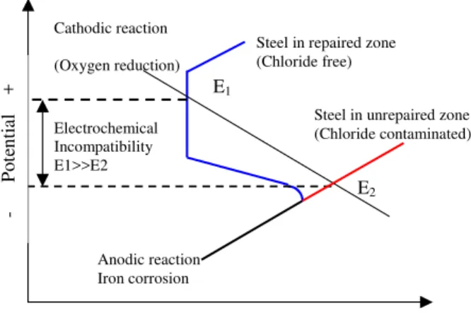
Electrochemical incompatibility is the imbalance in electrochemical potential between different locations of the reinforcing steel because of their dissimilar environments caused by a patch repair. Figure 1 shows a common explanation of corrosion mechanism in patch repairs, in which the chloride concentration in the substrate is higher than in the patch. The corrosion potential in the substrate, denoted by E2, is correspondingly lower than that in the patch (E1). The difference, or the incompatibility, in the corrosion potential is the driving force for macrocell corrosion to initiate. It was found that the resultant electrochemical potential difference can be as high as 500 mV. Under this circumstance, the steel in the substrate will serve as an anode, the steel in the patch area as a cathode, and the macrocell corrosion will form between the two areas.
A second explanation of corrosion mechanism in patch repairs was suggested2 in which a dense patching repair material is surrounded by a more porous concrete substrate. Due to the higher oxygen concentration in the substrate compare to the patch, its corrosion potential will be higher forcing the steel in the patch to serve as the anode, opposite to the first mechanism. However, experimental investigations have shown that the second case, oxygen gradient corrosion in the patch, is unlikely to occur under in-service conditions because the steel in the patch is most likely to be passivated. A relatively new condition arose with the increasing use of more corrosion-resistant steels (e.g. stainless steel) in some critical areas of concrete structures (e.g. top mats of concrete bridge decks) or replacing the original carbon steel in patch repairs. Since its corrosion-resistance is apparently incompatible with carbon reinforcing steels that is located nearly, the concern is that the galvanic coupling, or macrocell corrosion, might occur between the two types of steels and causes additional corrosion risk to the surrounding carbon steel.
The above understandings of electrochemical incompatibility however, have not considered the corrosion kinetics that directly determines the corrosion activities. Electrochemical incompatibility explains that macrocell corrosion is likely to occur; it does not suggest that macrocell corrosion will occur or it is the dominant corrosion mechanism in patch repairs. To know the answers, corrosion kinetics and its controlling factors such as concrete resistance must be considered. As a matter of fact, microcell corrosion was also used to explain the corrosion mechanism in patch repairs.9 It was proposed that the damaged area, before the repair, was more corrosive to the steel than the substrate and therefore served as an anodic (active) corrosion site, with the adjacent substrate being cathodically protected. This is illustrated in Fig.2 (a) by the current flow ( the positive charge flow through concrete is illustrated in the direction of the arrows) from the damaged area (anode) to the substrate (cathode). The repair process removed the corrosive environment in the damaged area and consequently, its cathodic protection on the steel in the substrate is lost. As a result, the steel in the substrate can develop active microcell corrosion, as shown in Fig.2 (b-1), in addition to the newly formed macrocell corrosion shown in Fig.2 (b-2).
The roles of these two corrosion mechanisms are not well understood in contributing to the overall corrosion damage. The use of electrochemical incompatibility to explain the corrosion mechanisms of patch repairs has overlooked the risks of microcell corrosion, which is further compounded by the fact that it cannot be easily detected by the simple technique of using a zero resistance Ampere meter normally used for detecting macrocell corrosion.
Microcell Corrosion Characteristics
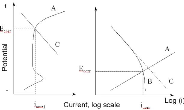
In normal concrete, pH of the pore solution varies between 12 and 13.5 and as a result, a passive film forms on the embedded reinforcing steel. The open circuit potential of a passivated steel is high (more positive) but the corrosion rate is very low (e.g. less than 0.1 μA/cm2
), and the overall reactions can be represented by the anodic (A) and cathodic (C) polarization curves in Fig.3. When this protective environment is adversely altered, e.g. by carbonation or chloride ions, active corrosion can develop. Compared with passivated steel, active steel is characterized by a low open circuit potential and a high corrosion rate, which is normally greater than 0.2 μA/cm,10
and its polarization curves A and C are also illustrated in Fig.3. If the active corrosion is under oxygen diffusion control, the cathodic reaction rate will be restricted to a limiting current and polarization C will be replaced by the bent curve B in Fig.3.
Both passivated steel and active steel can be microcell corrosion, and when the corrosion equilibrium is reached, both steels normally take up a more or less uniform electrode potential, often called the corrosion potential (Ecorr) (Fig.3). The corresponding rate of metal dissolution at this potential is referred to as the corrosion rate icorr, and is equal to the cathodic reduction current density ic (also equal to the anodic corrosion current density ia by the principle of charge conservation).
The microcell corrosion of reinforcing steel in concrete structures is often spave-variant, due to non-homogeneity and cracking in concrete or localized chloride attack. This also can be the case after a patch repair, considering: 1) a possible difference in chloride concentration between a new patch (chloride free) and its surrounding substrate (chloride contaminated); and 2) a possible difference in the corrosion potential due to different steel type or corrosion environment. For instance, the steel becomes passivated in the newly patched area and its electrochemical potential shifts to more positive values. On the other hand, the active corrosion could initiate in the nearby substrate with its corrosion potential shifting significantly towards more negative values.
Macrocell Corrosion Characteristics
Considering that the individual passivated steel (electrode 1) and active steel (electrode 2) (Fig.3) are now being put into close electrical contact (coupling) in an electrolyte or concrete, galvanic corrosion, also known as macrocell corrosion, can occur between the two steels. It is important to know the change in the rate of microcell corrosion due to the new macrocell corrosion and the rate of macrocell corrosion.
When this occurs, the changes of in the corrosion potential and corrosion rate of the two steels are illustrated in Fig. 4. The active steel, which has a more negative potential
current will increase from icorr2 (the corrosion current before coupling) to ia2’and the cathodic current decrease from icorr2to ic2’. On the other hand, the passive steel, having a more positive potential (Ecorr1), will be cathodically polarized to a more negative
potential; its anodic current will be reduced from icorr1to ia1’ and the cathodic current will be increased from icorr 1 to ic1’. The potentials of the two steels will eventually shift to a common potential (E’) and reach a new equilibrium, assuming the resistance of the concrete is negligible. At the new equilibrium, corrosion magnitude in terms of corrosion current density has the following relationship:
' ' ' ' 2 1 2 1 c a a c i i i i + = + (1)
Besides the microcell corrosion in which electrons are transferred from the anodic to cathodic sites in each of two individual electrodes, some electrons are now transferred from one electrode (the active steel, thereby called anode) to the other (the passive steel, thereby called cathode), forming the galvanic current (macrocell current):
' ' ' ' 1 2 2 1 a a c c mac i i i i i = − = − (2)
For the active steel, this macrocell current acts partially to enhance the anodic steel dissolution and partially to reduce the oxygen reduction reaction. The increase in the corrosion rate in the active steel, induced by the macrocell corrosion, can be determined from the following equation:
2 2' corr a corr i i i = − Δ (3)
Equations (2) and (3) clearly show that the increased anodic dissolution current density,
Δicorr is smaller than the macrocell corrosion current density (imac), because part of imac (about 40%) compensates for the decrease in the cathodic current of the active steel and the other part (about 60% of imac) contributes to the increase in the corrosion current, Δicorr. Their percentage contributions were calculated from the Tafel slopes of anodic and cathodic polarization on these steel bars that were measured as 40 mV/decade and 60 mV/decade, respectively. Therefore, it is not the macrocell corrosion but the increased anodic corrosion rate that accounts for the change in the corrosion activity in the active steel after being connected to a passivated steel.
The above two equations also show that both the macrocell and microcell currents exist on the anode of a macrocell. The relevant question is whether or not the formation of the macrocell suppresses the original microcell corrosion. This can be determined by
comparing the macrocell corrosion with the original microcell corrosion rate.
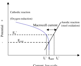
For a corroding reinforcing steel in concrete, the corrosion rate is often limited by the availability of oxygen at the steel/concrete interface. This is illustrated in Fig.5 by the oxygen reduction curve which becomes a vertical line, indicating almost no change in the oxygen reduction current even with further change in its potential. In that case, the cathodic reduction current at the coupled steel plays an important role. If the coupled steel is stainless steel, the cathodic reduction reaction rate will have a negligible change.
If the coupled steel is polarizable steel such as passive carbon steel, the coupling potential at the corroding steel shifts very little from its original corrosion potential on the active steel. Under these conditions, the overall corrosion current density remains approximately the same as the original microcell corrosion current density icorr. This was also illustrated by Andrade et al. (1992) in an explanation of correlation between macrocell and
microcell corrosion that the newly form macrocell corrosion does not necessarily suppress the original microcell corrosion, and the latter should not be ignored.
EXPERIMENTAL VERIFICATION Experimental Set-up
Corrosion in patch repairs has been simulated under two common conditions: 1) passive steel in patching concrete without chlorides and active steel in substrate concrete
containing chlorides: and 2) stainless steel in patching concrete without chlorides and carbon steel in substrate containing chlorides. The experimental setup for the simulation included two steel samples (electrodes) sitting in two respective electrochemical cells. One cell contains saturated Ca(OH)2 solution simulating the pore solution for patching concrete (without chlorides). The other cell contains saturated Ca(OH)2 solution with various concentrations of chlorides, simulating different conditions in substrate concrete. The two electrochemical cells were connected by a salt bridge as shown in Fig. 6.The steel electrodes (cylinders of 12.5 mm ×70 mm) for each cell were machined from reinforcing steel bars, including stainless steel (SS) 304LN, 316LN, 2205 and carbon steel (CS). The corroding CS electrodes, representing the active corrosion, were prepared by storing the electrodes in a humidity room for three weeks to allow the rust to
accumulate on their surfaces. The passive electrodes were prepared by leaving the electrodes in the saturated Ca(OH)2 solution (pH = 12.6) for one week.
The two steel electrodes in the cells were connected, simulating the condition of patch repairs. Following the formation of the macrocell, the microcell corrosion on the active steel and macrocell corrosion between the two steels were measured. The linear
polarization technique was used to determine the microcell corrosion current density by measuring the electrochemical polarization resistance (Rp) and thereby the corrosion rate (icorr) of the active steel in the cell. The macrocell current was measured and recorded using a Keithley 485 picoammeter connected to a PC computer after two steel electrodes were connected (with 1:1 ratio of apparent surface areas). More details on experimental set-up can be found in a previous paper11. In the present paper, all the potentials are presented relative to SCE.
Macrocell Corrosion Between Passive and Active Carbon Steels
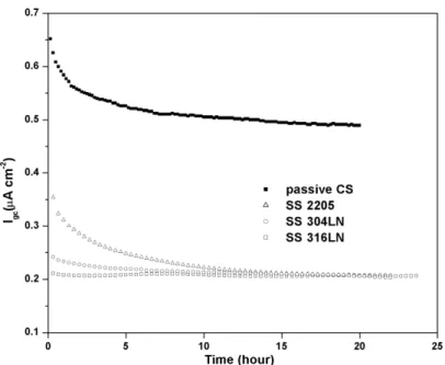
The macrocell current was directly measured when a corroding carbon electrode (e.g. substrate) was connected to a passive carbon electrode (e.g. patch repair area) in the electrochemical cells. In Fig.7 the line withsolid symbolswas the macrocell current
density, with Ecorr = –0.55 V for the corroding CS electrode. The macrocell corrosion current first showed an initial pulse, which was due to charging of double layer capacitors in the interface of electrolyte/steel, and decreased gradually with time until it reached a stable value. Recall that the corrosion activity on active steel includes both the remaining microcell corrosion and the newly formed macrocell corrosion. To assess the change in its corrosion state due to the macrocell corrosion, Table 1 lists the measured microcell, macrocell current densities, and their proportions, for three different corroding CS electrodes when they were coupled with a passive CS electrode, respectively. The three corroding CS electrodes had different corrosion potentials (Ecorr = –0.42V, –0.55 V, and – 0.6 V, vs SCE), representing different corrosion conditions of active reinforcing steel. For the active steel electrode with the corrosion potential of –0.6 V vs SCE, the microcell corrosion rate was 13.3 ± 0.4 μA/cm2
, and its macrocell current density, imacwas 0.53 μA/cm2
when it was coupled with the passivated steel. First, the magnitude of macrocell corrosion is only a small fraction, about 4%, of that of microcell corrosion, indicating that the microcell corrosion remains the dominant corrosion process on the active steel even when coupling with the passivated steel. Secondly, considering that only about 60% of the macrocell corrosion current (imac=0.53 μA/cm2) would contribute to the change in the corrosion activity(Δicorr) the increase in corrosion rate of the active steel caused by the macrocell corrosion is about 2.4%, as shown in Table 1. Therefore, the macrocell corrosion has increased the corrosion magnitude by a very small amount in the active steel.
When Ecorrbecomes less negative (from –0.60 mV to –0.42 mV), Table 1 shows that both the microcell and macrocell current densities at the active electrode become lower and the percentage increase in the corrosion rate due to the macrocell effect is also reduced. This indicates that the effect of macrocell corrosion would diminish with an increase in Ecorr while the microcell corrosion would increasingly dominate the whole corrosion process.
Macrocell Corrosion Between Stainless Steel and Carbon Steel
The macrocell current density between stainless steel (2205, 304LN and 316LN) and active carbon steel electrode measured in the electrochemical cell are also presented in Fig.7. It can be seen that the macrocell current density of the active carbon steel when coupled with stainless steel is less than half of that when it was coupled with the passive carbon steel. Considering the fact that electrochemical incompatibility is increased when a carbon steel is coupled with a stainless steel than with another carbon steel, this result seems contrary to the “expectation”. The reason is that although the stainless steel served as a greater driving force, due to high level of incompatibility with the carbon steel, the cathodic reduction reaction on stainless steel is significantly lower than that on passive carbon steel. In this case, the cathodic-reduction reaction rate on stainless steel is the rate-determining step of the macrocell corrosion process. The slower cathodic reaction rate on its surface makes the actual coupling corrosion current less significant.
This experimental observation has confirmed the earlier discussion that the macrocell current density depends on the shape of the oxygen reduction (cathodic reaction) curve. The result implies that the use of stainless steel reinforcement in patch repair areas that are reinforced by carbon steel will not increase the risk of corrosion on the carbon steel reinforcement, and considering the electrochemical incompatibility without the corrosion kinetics is not enough to derive correct information about actual corrosion risks.
Note the results presented here are based on the 1:1 electrode ratio, which assumed corrosion in patch repairs are between the steel in patch area and the steel in surrounding substrate with the same amount of surface area. It is more applicable for reinforcing steel with relative large corrosion areas since the non-corroding area on surrounding rebars are in similar or comparable size. However for pitting corrosion, which produces a very small corrosion area (such as pin holes), the non-corroding area on surrounding rebars could be relatively large and the macrocell corrosion could become relatively more significant than illustrated in this paper.
CONCLUSIONS
Theoretical and experimental studies of macrocell and microcell corrosion rates were undertaken on coupled steel samples simulating those in patch repairs. Microcell corrosion was found to be the dominant corrosion process on the corroding carbon steel in chloride-containing substrate concrete, when coupled with passive carbon steel in chloride-free patching concrete. The effect of macrocell corrosion would became even less significant when the corrosion potential of the corroding electrode became less negative. When carbon steel was replaced by stainless steel in patch areas, it did not induce significant macrocell corrosion risk for the surrounding carbon steel, because the cathodic reduction current on stainless steel is significantly lower than that on passive carbon steel. It implies that the use of stainless steel instead of carbon steel reinforcement in repair areas would not increase the risks of corrosion due to their apparent
incompatibility. Both theoretical examination and experimental study showed that the concept of electrochemical incompatibility must be considered in terms of corrosion kinetics in order to understand the actual corrosion activities, both macrocell and
microcell corrosion, in patch repairs of concrete structures, in order to assess properly the corrosion risk and the efficiency of preventive methods.
REFERENCE
1. Emberson, N.K. and Mays, G.C. , “Significance of properties mismatch in the patch repair of structural concrete Part 1 properties of repair systems,” Magazine of Concrete Research, 1990, 42: 147-160.
2. Gu, P., Beaudoin, J. J., Tumidajski, P. J., and Mailvaganam, N. P., “Electrochemical incompatibility of patches in reinforced concrete,” Concrete International, 1997,19: 68-72.
3. Wheat, H.G., and Harding, K.S., “Galvanic corrosion in repaired reinforced concrete slabs-an update,” Materials Selection and Design, 1993, 5: 58-62.
4. Schieβl, P. and Breit, W., “Local repair measures at concrete structures damaged by reinforcement corrosion – aspect of durability,” International Symposium on Corrosion of Reinforcement in Concrete Construction, Royal Society of Chemistry, 1996, SP 183: 327-336.
5. Pruckner, F. and Gjφrv, O.E., “ Patch repair and macrocell activity in concrete structures,” ACI Materials Journal, 2002, 99: 143-148.
6. Li, G., and Yuan, Y.S., “Electrochemical incompatibility for patch-repaired corroded reinforced concrete,” Journal of China University of Mining and Technology, 2003,
32: 44-47.
7. Andrade, C., Maribona, I. R., Feliu, S., Gonzalez, J. A., and Feliu, S. Jr., “The effect of macrocells between active and passive areas of steel reinforcement,” Corrosion Science, 1992. 33: 237-249.
8. Bertolini, L., Bolzoni, F. Pastore, T. and Pedeferri, P., “Behaviour of stainless steel in simulated concrete pore solution,” British Corrosion Journal, 1996, 31: 218-222. 9. Raupach, M., “Chloride-induced macrocell corrosion of steel in concrete--theoretical
background and practical consequences,” Construction and Building Materials, 1996,
10: 329-338.
10. Andrade, C. and Gonzales, J.A., “Quantitative measurement of corrosion rate of reinforcing steels embedded in concrete by polarization resistance measurements,” Werkstoffe und Korrosion, 1978, 29: 515-519.
11. Qian, S, Zhang, J. and Qu, D., “Experimental and Theoretical Examination on Macrocell Corrosion and Microcell Corrosion in Patch Repair, Cement and Concrete Composites,” 2006, 28(8): 685-695
Table 1. Relationship between imac and imic for passive carbon steel coupled with corroding carbon steel at different Ecorr (vs SCE) Ecorr at corroding electrode imac *
(μA/cm2 ) imic * (μA/cm2 ) imac/imic (%)
Δicorr/icorr (%)
-0.60 V 0.53 13.3 4.0 2.4
-0.55 V 0.44 12.8 3.4 2.0
-0.42 V 0.04 1.42 2.8 1.7
- Po te ntial + Anodic reaction Iron corrosion
Current, log scale Electrochemical
Incompatibility E1>>E2 Cathodic reaction (Oxygen reduction)
Steel in repaired zone (Chloride free)
Steel in unrepaired zone (Chloride contaminated) E1
E2
Figure 1. Schematic polarization curves showing electrochemical incompatibility between repaired and unrepaired area contaminated by chloride (adapted from Gu et al.
1997)
(a) Current distribution before repair
Damaged zone Undamaged zone
Repaired zone Unrepaired zone Repaired zone Unrepaired zone
Cathodically protected
(b) Current distribution after repair
(b-1) Microcell corrosion by loss of cathodic protection (b-2) Macrocell corrosion
Figure 2. Schematic representation of corrosion current through concrete by positive
Figure 3. Schematic polarization curves of reinforcing steel in concrete structures
Poten tial + Anodic reaction (steel oxidation)
Current, log scale Cathodic reaction (Oxygen reduction) Ecorr Icorr Ea’ Ic’ Ia’ Macrocell current
Figure 5. Schematic of macrocell corrosion and microcell corrosion of active steel by oxygen
Figure 7. Galvanic current density of corroding carbon steel coupled with different steels in a saturated Ca(OH)2 solution.