HAL Id: hal-01881386
https://hal.uca.fr/hal-01881386
Submitted on 25 Sep 2018
HAL is a multi-disciplinary open access
archive for the deposit and dissemination of
sci-entific research documents, whether they are
pub-lished or not. The documents may come from
teaching and research institutions in France or
abroad, or from public or private research centers.
L’archive ouverte pluridisciplinaire HAL, est
destinée au dépôt et à la diffusion de documents
scientifiques de niveau recherche, publiés ou non,
émanant des établissements d’enseignement et de
recherche français ou étrangers, des laboratoires
publics ou privés.
LoRa Throughput Analysis with Imperfect Spreading
Factor Orthogonality
Antoine Waret, Megumi Kaneko, Alexandre Guitton, Nancy El Rachkidy
To cite this version:
Antoine Waret, Megumi Kaneko, Alexandre Guitton, Nancy El Rachkidy. LoRa Throughput Analysis
with Imperfect Spreading Factor Orthogonality. IEEE wireless communications letters, IEEE comsoc,
In press. �hal-01881386�
1
LoRa Throughput Analysis with Imperfect
Spreading Factor Orthogonality
Antoine Waret
∗, Megumi Kaneko
∗, Alexandre Guitton
†, and Nancy El Rachkidy
†∗
National Institute of Informatics, 2-1-2 Hitotsubashi, Chiyoda-ku, 101-8430 Tokyo, Japan
†University Clermont Auvergne, CNRS, LIMOS, F-63000 Clermont-Ferrand, France
Email: [email protected], [email protected],
{alexandre.guitton,nancy.el rachkidy}@uca.fr
Abstract— LoRa is one of the promising techniques for
en-abling Low Power Wide Area Networks (LPWANs) for future Internet-of-Things (IoT) devices. Although LoRa allows flexible adaptations of coverage and data rates, it is subject to intrinsic types of interferences: co-SF interferences where end-devices with the same Spreading Factors (SFs) are subject to collisions, and inter-SF interferences where end-devices with different SFs experience collisions. Most current works have considered perfect orthogonality among different SFs. In this work, we provide a theoretical analysis of the achievable LoRa throughput in uplink, where the capture conditions specific to LoRa are included. Results show the accuracy of our analysis despite approximations, and the throughput losses from imperfect SF orthogonality, under different SF allocations. Our analysis will enable the design of specific SF allocation mechanisms, in view of further throughput enhancements.1
Keywords: LoRa, Spreading Factor, Uplink Throughput,
Imperfect Orthogonality
I. INTRODUCTION
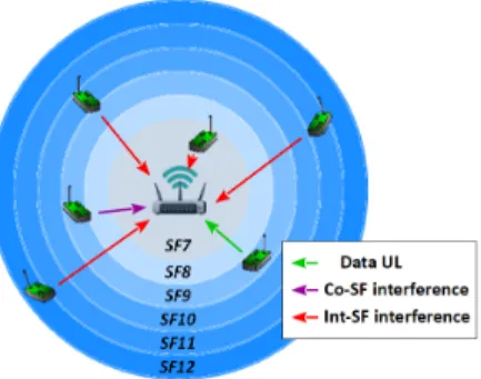
As the amount of mobile data traffic will rapidly increase during the upcoming years (studies forecast 50 billion Internet of Things (IoT) devices by 2020), new spectrum access strategies adapted to high device densities are ever more crucial. LoRa [1] is one of the prominent candidates for Low Power Wide Area Networks (LPWANs), providing wide communication coverage with low power consumption, at the expense of data rate. Operating in license-free ISM bands (i.e., 868MHz in Europe), the LoRa PHY layer uses a chirp spread-spectrum modulation where different Spreading Factors (SFs) tune the chirp modulation rates. Lower SFs such as SF7 allow for higher data rates but reduced transmission range, whereas higher SFs such as SF12 provide longer range at lower data rates. On top of the LoRa PHY layer, the higher layers were defined by the LoRa Alliance and referred as LoRaWAN [2]. In particular, the MAC protocol is based on a pure ALOHA access with duty cycle limitations. The LoRaWAN network architecture is a star-like topology where end-devices communicate with gateways over several channels.
Most studies on LoRa scalability so far assumed a perfect orthogonality among SFs, thereby creating virtual channels where multiple users with different SFs could simultaneously operate in the same channel and hence boost the achievable system throughput. Thus, a number of works have consid-ered the effect of co-SF interference only, where end-devices
1This work was supported by the Grant-in-Aid for Scientific Research
(Kakenhi) no. 17K06453 from the Ministry of Education, Science, Sports, and Culture of Japan and by the NII Research Grant.
Fig. 1. LoRa system setup - Case of SF-distance allocation
using the same SF on the same channel are subject to colli-sions [3][4]. In particular, the outage probability of a LoRa system under co-SF interference was analyzed in [3], where a signal could be captured if its Signal-to-Interference-plus-Noise Ratio (SINR) was higher than 6 dB. As the number of devices increased, it was shown that those co-SF interferences were causing a scalability limit. However, recent studies have pointed out the fact that SFs were not perfectly orthogonal among themselves [5]. Thus, the effect of inter-SF collisions was investigated through computer simulations and/or experi-ments. Namely, [5][6] showed that inter-SF interferences could considerably decrease LoRa performance, especially for high SFs where frames have a greater time on air.
In this work, we propose a theoretical analysis of the achievable throughput on the uplink of a LoRa network, encompassing the effects of co- and inter-SF interferences. To ensure a successful transmission, a packet must thus satisfy three conditions: 1) its SNR is above the reception threshold, 2) its SINR under co-SF interference is above the co-SF capture threshold, and its SINR under inter-SF interference is above the inter-SF capture threshold. Considering two different types of SF allocations, we theoretically derive the achievable throughput expressions for both perfect and imperfect SF orthogonality. Simulation results show the accuracy of our analytical expressions despite the necessary approximations, as well as the impact of the various types of interferences and SF allocations on the overall system performance.
II. SYSTEMMODEL
We consider one cell of radius R with one gateway located at its center, as depicted in Fig. 1. There are N end-devices
uniformly distributed within the cell. We denote by di the
distance from end-device i to the gateway. Since the goal of our analysis is to derive the achievable rate by LoRa, we assume that all end-devices transmit in a single channel of bandwidth
BW = 125kHz and that they all have packets to transmit.
This corresponds to the pure ALOHA access as in LoRaWAN with saturated traffic2. We consider M = 6 SFs, for m =
{mmin, ..., mmax}, with mmin = 7 and mmax = 12, with
symbol times Tm= 2 m BW. The bit-rate Rm of SFm is [1] Rm=m× CR2m BW ,
where CR is the coding rate defined as 4/(4 + n) with
n ∈ {1, 2, 3, 4}. Lower SFs allow higher data rate but lower
communication range whereas higher SFs provide longer range at the expense of data rate (see Table I).
Two types of SF allocation will be investigated. In the first one, the spreading factors are uniformly distributed, i.e., every end-device has a probability pm = M1 of selecting SFm. We
refer to this allocation as SF-random. In the second type of allocation referred to as SF-distance, spreading factors are assigned according to the distance di. A device located inside
the annulus defined by the smaller and larger circle radii
lm−1 and lm, respectively, has SFm. The distance threshold lm for SFm is given by lm = ( P0A(fc) θrxm )1 α , where A(fc) = (fc2×10−2.8)−1is the deterministic loss in the path loss model Li=
A(fc)
dα
i as in [7], fc the carrier frequency and α the path
loss exponent. θrxm is the receiver sensitivity of SFm (see
Table I). All nodes transmit at equal power P0. We assigned
to l6 and l12 the origin of the cell and its radius respectively,
i.e., l6= 0 and l12= R. The ranges for each SF are given in
Table I. The probability of selecting SFm for the SF-distance
allocation is then given by pm=
∫lm
lm−1h(r)dr, where h(r) is
the pdf of the position of an end-device in the cell at distance
r from the gateway. For uniform distribution of devices within
a cell of radius R, we get h(r) = R2r2.
The instantaneous SNR γi of end-device i is defined as γi = P0|hi|2Li/σ2n, where|hi|2 is the channel gain between
end-device i and the gateway (for Rayleigh fading, hi ∼ CN (0, 1)). σ2
n = −174 + NF + 10 log(BW ) [dBm] is the
AWGN power and NF, the receiver noise figure.
Based on [5], it is assumed that in the event of a colli-sion between frames of different SFs, one signal is received successfully if its SINR is higher than its “InterSF capture threshold” in Table I. Moreover, if there are several signals with equal SFs transmitting on the same frequency simultane-ously, the gateway is able to successfully receive one of them if its SINR is higher than 6 dB, for any SFm[3][8]. Therefore,
both types of interferences will be considered. III. PROPOSEDTHROUGHPUTANALYSIS
An end-device’s packet transmission in uplink is success-fully received at the gateway if the three following conditions are fulfilled:
1) Reception condition:
2Our analysis can be easily applied to multiple channels and duty cycles.
SFm Bit-rate Rm [kb/s] Receiver Sensi-tivity[1] θrxm [dBm] Reception thresh. qSFm [dB] InterSF capture thresh.[5] qiSFm [dB] Dist. thresh. lm [km] 7 5.47 -123 -6 -7.5 0∼ 0.453 8 3.13 -126 -9 -9 0.453∼ 0.538 9 1.76 -129 -12 -13.5 0.538∼ 0.639 10 0.98 -132 -15 -15 0.639∼ 0.760 11 0.54 -134.5 -17.5 -18 0.760∼ 0.877 12 0.29 -137 -20 -22.5 0.877∼ 1 TABLE I LORACHARACTERISTICS ATBW = 125KHZ, α = 4ANDR = 1KM
Signal power must be above the SF-specific threshold qSFm,
Pcapi
rx m = P (γi ≥ qSFm), (1)
which is the probability that a received signal from end-device
i at a distance di from the gateway has a SNR γi above the
threshold qSFm(Table I).
2) Co-SF capture condition:
The co-SF SINR of end-device i is defined as SINRicoSF=
γi
∑K
k=1γk+ 1
, (2)
where K is the number of end-devices with the same SF as end-device i. A signal is successfully received if its SINRicoSF
is above qcoSF. Therefore, the second condition is given by
Pcapi coSF = P ( γi ∑K k=1γk+ 1 ≥ qcoSF ) . (3)
3) Inter-SF capture condition:
As shown in [5][6], SFs are not perfectly orthogonal: a signal at SFmfaces interferences from all N − K signals on
other SFs. The inter-SF SINR of end-device i is defined as SINRiintSF=∑N γi
p=K+1γp+ 1
. (4)
A transmission is successful if SINRiintSF is higher than the
threshold qiSFm, thus the third condition is given as
Pcapi intSF m = P ( γi ∑N p=K+1γp+ 1 ≥ qiSFm ) . (5) Therefore, the uplink throughput τ can be expressed as
τ = m∑max
m=mmin
Rm × Psuccess(SFm), (6)
where Rm is the bit-rate of SFm and Psuccess(SFm), the
probability of a successful transmission.
Next, we analyze the throughput under perfect and imperfect SF-orthogonality, for the SF-distance case.
A. Perfect Orthogonality
We assume first that SFs are perfectly orthogonal, i.e., no end-device suffers inter-SF interferences. Hence, the probabil-ity of a successful transmission Psuccess(SFm) is given by Psuccess(SFm) = N ∑ j=1 ( N j )
pjm(1−pm)N−jP (caprx, capcoSF),
where j denotes the total number of end-devices at SFm,
(N
j
)
pj
m(1 − pm)N−j is the probability of having j
end-devices among N at SFm and P (caprx, capcoSF) is the joint
probability for reception condition and co-SF capture.
1) For j = 1: the end-device is not subject to co-SF
interferences, thus only the reception condition needs to be satisfied,
P (caprx, capcoSF) = Pcapi rx m.
First, we determine Pi
caprx m for the SF-distance case. Given
our assumptions, the SNR γi is modeled as an exponential
random variable with mean γi. Therefore, Pcapi
rx m = P (γi≥ qSFm|γi)× P (γi),
where qSFm is the specific threshold of SFm. Defining γi= c
rα i
, where c = P0×A(fc)
σ2
n is the path-loss constant, we can now
rewrite, Pcapi rx m = ∫ lm lm−1 exp ( −qSFmriα c ) ×2ri R2dri. (8)
Although this integral cannot be expressed in closed form, it can be efficiently determined by numerical methods.
2) For j ≥ 2: both the reception and co-SF conditions
must be fulfilled. As qSFm≤1 in linear for all SFs whereas qcoSFm = 4 (6 dB) for all SFs as explained in Section II, if co-SF capture is satisfied, so is the reception condition, hence
P (caprx, capcoSF) = Pcapi coSF.
In case of co-SF interferences, there are j-1 interferers,
Pi capcoSF = P ( γi ∑j−1 k=1γk+1 ≥ qcoSF ) , which is developed using random instantaneous SNR variables γk and random
average SNR (position) variables γk as P ( γi ∑j−1 k=1γk+1 ≥ qcoSF|γ1 , ..., γi, ..., γj−1, γ1, ..., γj−1 )
×P (γ1, ..., γi, ..., γj−1, γ1, ..., γi−1, γi+1, ..., γj−1).
Marginalizing over γ1, ..., γj−1 and making the change of
variable γi= rcα i
, we get by independency of user channels,
Pcapi coSF= ∫ lm lm−1 exp(−qcoSFr α i c )× j∏−1 p=1 p̸=i ∫ lm lm−1 h(rp)drp 1 + qcoSF ( ri rp )αh(ri)dri. We define I(ri) = ∫lm lm−1 h(r)dr 1+qcoSF ( ri rp
)α. Nodes are
uni-formly distributed within the cell, therefore ∏jp=1−1I(ri) = [I(ri)]j−1. As a result, the expression becomes,
Pcapi coSF = ∫ lm lm−1 exp ( −qcoSFriα c ) [I(ri)]j−1h(ri)dri. (9)
In particular, for α = 4, the primitive function of I(ri) is J (ri, r) = (r R )2 −(ri R )2√ qcoSFarctan ( 1 (r i r )2√ qcoSF ) . (10)
In case of co-SF interferences, the interferers are the end-devices with the same SF as end-device i, thus with the same distance boundaries. The expression of I(ri) becomes
I(ri) = J (ri, lm)− J(ri, lm−1). (11) Therefore, (7) can be written for SF-distance allocation with perfect SF orthogonality as,
Psuccess(SFm) = ( N 1 ) (1− pm)N−1× Pcapi rx m + N ∑ j=2 ( N j ) (1− pm)N−j× Pcapi coSF, (12) with Pi
caprx m given in (8) and Pcapi coSF in (9).
B. Imperfect Orthogonality
In reality, spreading factors are not perfectly orthogonal, so all three capture conditions are to be satisfied to achieve a successful transmission. Thus, Psuccess(SFm) becomes
Psuccess(SFm) = N ∑ j=1 ( N j ) pjm(1− pm)N−j
×P (caprx, capcoSF, capintSF), (13)
where P (caprx, capcoSF, capintSF) is the joint probability for
reception condition, capture co-SF and capture inter-SF.
1) For j = 1: the end-device is only subject to inter-SF
interferences and the reception condition. As shown in Table I, the inter-SF condition is dominant over the reception one, especially as the number of end-devices increases. Thus,
P (caprx, capcoSF, capintSF) = Pcapi intSF m.
The expression of Pi
capintSF m is similar to Pcapi coSF, only with
different thresholds and number of interferers. When dealing with inter-SF interferences, one must consider the end-devices within the cell that are not in the annulus corresponding to SF
m, i.e., the end-devices with a different spreading factor. If j
is the number of end-devices at SFm, then there are N− j
end-devices with other spreading factors. Therefore,
Pcapi intSFm = ∫ lm lm−1 exp ( −qiSFmr α i c ) [ eI(ri)]N−jh(ri)dri. (14) Here, eI(ri) =∫R\R m h(r)dr 1+qcoSF ( ri rp )α, where R \ Rm denotes
the whole cell area excluding the area corresponding to SFm.
Using (10), we obtain
eI(ri) = J (ri, R)−J(ri, 0)−[J(ri, lm)− J(ri, lm−1)] . (15) 2) For j ≥ 2: all capture conditions are to be considered.
As in the perfect orthogonality case, the reception condition derives from the two others, thus
P (caprx, capcoSF, capintSF) = P (capcoSF, capintSF). (16)
Because of the difficulty to find an exact expression of (16), as one condition might be dominant over the other depending on j, we approximate it as
P (capcoSF, capintSF)≈ min(Pcapi intSF m, P
i
0 5 10 15 20 25 30 35 40 45 50 Number of end-devices 0 0.5 1 1.5 2 2.5 3 3.5
Average Throughput [kbits/s]
SF-dist. Perfect (SIMU) SF-dist. Perfect (ANA) SF-distance Imperfect (SIMU) SF-distance Imperfect (ANA)
Fig. 2. Throughput performance of SF-distance allocation for both perfect and imperfect orthogonality – R = 1km, α = 4
Finally, (13) can be written for SF-distance allocation with imperfect orthogonality as,
Psuccess(SFm) = ( N 1 ) × Pi capintSF m + N ∑ j=2 ( N j )
(1− pm)N−jmin(Pcapi intSF m, P
i
capcoSF), (17)
where Pcapi intSF m is given in (14) and Pcapi coSF in (9).
Due to lack of space, the analytic throughput expressions for the SF-random case are not given, as they can be obtained similarly as for SF-distance.
IV. NUMERICALRESULTS
System throughput was evaluated for perfect/imperfect or-thogonality as well as for both types of allocations, to assess the validity of our analytical expressions. The main parameters are fc = 868 MHz, BW = 125 kHz and the end-devices’
transmit power P0= 14 dBm. The path loss exponent was set
to α = 4 as in [3] (urban) and R = 1 km.
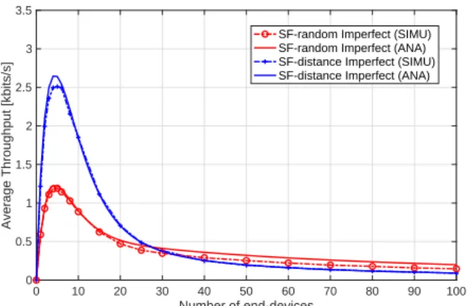
Fig. 2 shows throughput performance obtained by simu-lations and by our theoretical derivations under SF-distance allocation for both perfect and imperfect orthogonality against varying numbers of end-devices transmitting simultaneously. We observe that our derived throughput expressions approach almost perfectly the simulations results with only a small interstice for small values of N (around 5 end-devices) in the imperfect orthogonality case. Therefore, despite approxi-mations, we obtain accurate throughput expressions for both orthogonality cases. Next, we can see that SF inter-ferences cause an early decrease of performance compared to the perfect orthogonality case. However, as the number of devices increases, co-SF interferences always lead to a scalability limit. These results show the impact of imperfect SF orthogonality over the system throughput, up to 50% loss. Next, the throughput performance for both types of alloca-tions with imperfect orthogonality are shown in Fig. 3. First, we can see that our analysis provides a good approximation of the achievable throughput under SF-random allocation. Then, we notice that for a small amount of end-devices (less than 25), better throughput efficiency is achieved in SF-distance allocation case (up to 100% gain), since devices are more
0 10 20 30 40 50 60 70 80 90 100 Number of end-devices 0 0.5 1 1.5 2 2.5 3 3.5
Average Throughput [kbits/s]
SF-random Imperfect (SIMU) SF-random Imperfect (ANA) SF-distance Imperfect (SIMU) SF-distance Imperfect (ANA)
Fig. 3. SF-random and SF-distance allocation throughput performances with imperfect orthogonality – R = 1km, α = 4
likely to satisfy the specific threshold qSFm. On the other hand, SF-random allocation performs slightly better for greater values of N . Given the higher density of co-SF end-devices under distance, these results suggest that even a simple SF-random policy provides a higher throughput as the number of end-devices increases. This is because the SF-random allocation favors the case where a limited number of devices randomly choose a small SF, by decreasing their collision probability. Moreover, small SFs lead to larger throughput than large SFs. Thus, our analysis will be useful to devise new allocation policies under various conditions and environments.
V. CONCLUSION
We have considered the uplink of a single gateway LPWAN based on LoRa physical layer, for which a theoretical through-put expression was derived. Unlike most previous works, our analytical expression encompasses all three conditions required for successful frame transmission: SNR reception level, SINR level for co-SF capture, and SINR level for inter-SF capture. Results have shown the non-negligible impact of SFs’ imperfect orthogonality, as well as the drastic effects of SF allocations on the overall throughput. Our analytic frame-work hence provides a precious tool for designing tailored SF allocations depending on environments and requirements, by predicting their impact on system performance.
REFERENCES
[1] “LoRa Modulation Basics - AN1200.22, Revision 2,” Semtech Corpora-tion - www.semtech.com, May 2015.
[2] “LoRaWAN - What is it?, A technical overview of LoRa and LoRaWAN,” LoRa Alliance - www.lora-alliance.org, 2015.
[3] O. Georgiou and U. Raza, “Low Power Wide Area Network Analysis: Can LoRa Scale?” IEEE Wireless Communications Letters, vol. 6, no. 2, pp. 162–165, April 2017.
[4] M. Bor, U. Roedig, T. Voigt and J.M. Alonso, “Do LoRa Low-Power Wide-Area Networks Scale?” in ACM MSWiM, Malta, November 2016. [5] D. Croce, M. Gucciardo, I. Tinnirello, D. Garlisi and S. Mangione,
“Impact of Spreading Factor Imperfect Orthogonality in LoRa Commu-nications,” Springer, Towards a Smart and Secure Future Internet, vol. 766, September 2017.
[6] G. Zhu, C.-H. Liao, M. Suzuki, Y. Narusue and H. Morikawa, “Evaluation of LoRa Receiver Performance under Co-technology Interference,” in
IEEE CCNC, Las Vegas, USA, January 2018.
[7] “Propagation data and prediction methods for the planning of indoor ra-diocommunication systems and radio local area networks in the frequency range 300 MHz to 100 GHz,” Recom. ITU-R P.1238-9, 2017.
[8] C. Goursaud and J.-M. Gorce, “Dedicated networks for IoT:PHY/MAC state of the art and challenges,” EAI Endorsed Trans. Internet of Things, 2015.