Publisher’s version / Version de l'éditeur:
Journal of Fire Sciences, 2, 3, pp. 179-188, 1984-05
READ THESE TERMS AND CONDITIONS CAREFULLY BEFORE USING THIS WEBSITE. https://nrc-publications.canada.ca/eng/copyright
Vous avez des questions? Nous pouvons vous aider. Pour communiquer directement avec un auteur, consultez la première page de la revue dans laquelle son article a été publié afin de trouver ses coordonnées. Si vous n’arrivez pas à les repérer, communiquez avec nous à PublicationsArchive-ArchivesPublications@nrc-cnrc.gc.ca.
Questions? Contact the NRC Publications Archive team at
PublicationsArchive-ArchivesPublications@nrc-cnrc.gc.ca. If you wish to email the authors directly, please see the first page of the publication for their contact information.
NRC Publications Archive
Archives des publications du CNRC
This publication could be one of several versions: author’s original, accepted manuscript or the publisher’s version. / La version de cette publication peut être l’une des suivantes : la version prépublication de l’auteur, la version acceptée du manuscrit ou la version de l’éditeur.
For the publisher’s version, please access the DOI link below./ Pour consulter la version de l’éditeur, utilisez le lien DOI ci-dessous.
https://doi.org/10.1177/073490418400200303
Access and use of this website and the material on it are subject to the Terms and Conditions set forth at
Combustibility of insulation in cavity walls
Choi, K. K.; Taylor, W.
https://publications-cnrc.canada.ca/fra/droits
L’accès à ce site Web et l’utilisation de son contenu sont assujettis aux conditions présentées dans le site LISEZ CES CONDITIONS ATTENTIVEMENT AVANT D’UTILISER CE SITE WEB.
NRC Publications Record / Notice d'Archives des publications de CNRC:
https://nrc-publications.canada.ca/eng/view/object/?id=c2d1d491-643e-4571-b6c4-f1a3e7128cc9 https://publications-cnrc.canada.ca/fra/voir/objet/?id=c2d1d491-643e-4571-b6c4-f1a3e7128cc9,Ser
National Research
Conseil national
/
,2
33O
Tm
1
$I
Council Canada
de recherches Canada
N21d
no.
1248
c. 2 IBrnG
1
CAVITY WALLSby K.K. Choi and W. Taylor
! s t
+ I O T M $ Q U E
Reprinted from
.rch h , i m
Journal of Fire Sciences, L:
-
I C. . . b Vol. 2, No. 3, May/June 1984
p. 1 7 9 - 188
DBR Paper No. 1248
Division of Building Research
I
On augmente d e p l u s e n p l u s l a q u a n t i t 5 d ' i s o l a n t t h e r m i q u e d a n s l e s b s t i m e n t s p o u r r g d u i r e l a consommation d 1 6 n e r g i e . Dans l e s b l t i m e n t s d e c o n s t r u c t i o n i n c o m b u s t i b l e , il e s t p r 6 f C r a b l e p o u r l e rendement t h e r ~ n l q u e e t l a s b c u r i t B i n c e n d i e d e p l a c e r l ' i s o l a n t d a n s l a c a v i t g d e s murs e x t g r i e u r s . L ' u t i l i s a t i o n d e mousses p l a s t i q u e s i s o l a n t e s a Bt6 riiglementge e n r a i s o n d e s c a r a c t ' e r i s t i q u e s d 1 i n f l a m m a b i l i t 5 mises e n e v i d e n c e g a r d e s e s s a i s e n t r e p r i s d a n s c e b u t . 11 a C t 6 a d d s d l a s u i t e d ' e s s a i s c o m p a r a t i f s d e s mousses i s o l a n t e s e t d ' a u t r e s t y p e s d ' i s o l a n t que l e s mgthodes e m p l o y h s n e p e r m e t t a i e n t p a s d 1 6 v a l u e r convenablement l e comportement a u f e u d e s mousses p l a s t i q u e s p l a c 6 e s d a n s l e s murs c r e u x .
COMBUSTIBILITY OF
INSULATION IN CAVITY WALLS
C
K.
K.
CXoiDivision of BuiMing Research
L National Reseamh Council o f Canada Ottawa, O n W
K I A OR6
K
Taylor
Esso Chemical C&
2300 Yonge St. Toronto, O n W M5W 1K3 (Received February 24. 1984) (Revised June 21. 1984)
1
ABSTRACT IIncreasing amounts of insulation are used in buildmgs to conaerve energy. In buildings of noncombustible construction, insulation ia usually placed in the wall cavity with or without an air space. The use of foamed plastic insuletion has been restricted due to its combustibility characteristics when tested by methods adopted for regulatory purposes. A series of teats on foamed plastics and con- ventional insulation materials show that these methods do not realistically assess the fire performance of foamed plastic insulation when used in cavity
1
w&.I
INTRODUCTIONI N CANADA AND THE UNITED STATES, MORE THAN ONE THIRD OF THE total energy consumption is used for heating and cooling of buildings. The efficient use of energy in buildings is therefore of paramount impor-
tance if the objective of energy conservation is to be met. One of the
most effective measures of reducing energy consumption in buildings is
1
Part
of this per was presented at "Cooperating to Fight Fire." the Third Symposium on ~ o r n b u s t i b g ~ and Plastics. Toronto. October 24-28. 1983.b add insulation to the building envelope. Unfortunately, the use of in- sulation to improve the energy efficiency of buildings may adversely af- fect fire safety. One of the potential hazards is the spread of fire in con-
cealed spaces of buildings. particularly in cavity waUs containing com- bustible insulation. Some of the pertinent aspects of this problem md their investigation are discussed in this paper.
CAVITY WALLS
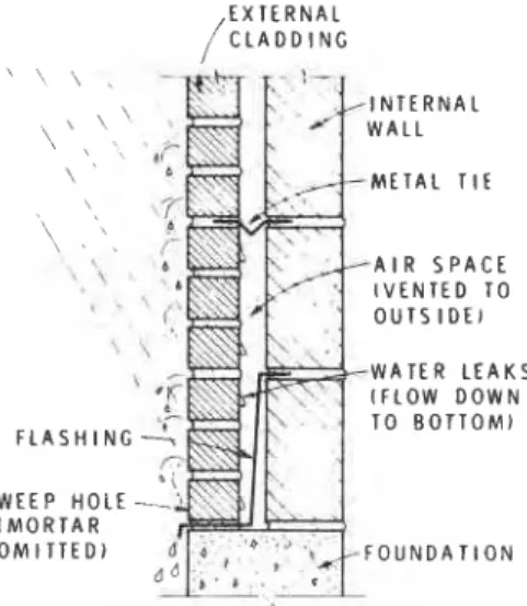
Cavity w d construction was developed to overcome the poor resistance of solid walls to rain penetration [I].
This
type of conatruc- tion consists of an external cladding separated from the internal wallby an air space, or cavity, that is vented to the atmosphere. Since there
is very little pressure difference between the outer and inner surfaces
of the cladding. rainwater driven through the unavoidable leaks by wind, gravity and capillary forces tends to flow down its inner surface. The water is intercepted by the flashing a t the bottom of the cavity and led back to the outside through weep holes. The cladding therefore acts as a screen for rainwater, keeping the wall dry. A typical cavity wall construction is illustrated in Figure 1.
INSULATING CAVITY WALLS
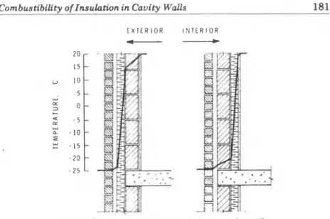
When insulating a cavity wall, insulation can be placed on the inner or the outer face of the internal wall (Figure 2). If it is placed on the in-
E X T E R N A L / C L A D D I N G I N T E R N A L W A L L \ M E T A L T I f W A T E R L E A K S I F L O W D O W N T O B O T T O M ) W E E P HOLE-- I M O R T A R O M I T T E D )
Combustibilitv of Insulation in Cavih Walls 181
E X T E R I O R I N T E R I O R
-
Figure 2. Two methods o f insulating a cavity wall.
side face, the entire masonry wall will be kept a t or near the outdoor temperature and the masonry will be subjected to compressive and tensile stresses due to changes in temperature and moisture content. Such an arrangement can cause cracking and results in frequent ther- mal bridges a t floor and roof slabs and a t cross-walls, since the struc- ture generally remains uninsulated at these locations.
By placing the insulation a t the outside face of the internal wall, the entire structure is maintained a t a relatively constant temperature and humidity, minimizing the disruptive dimensional changes that can result in cracking.
CAVITY WALL INSULATION
Although in principle any insulation material can be used in cavity walls, in practice only a few are suitable for such an application. Those most widely used fall into two categories: glass fiber and foamed plastic.
Glass fiber insulation is a rigid board consisting of fibers of glass bonded together with a resin binder. The board is sometimes faced with a vapour barrier to control water permeability. This type of in- sulation is normally regarded as a low-firehazard material although it is not classified as noncombustible due to the presence of the binder. Foamed plastic insulation can be made of polystyrene, polyurethane, polyisocyanurate or phenolic, and is usually produced in the form of rigid boards. However, polyurethane foam can also be applied on-site by spraying or pouring.
ignited.
The
National Building Code of Canada [2] requires that all foamed plastics, when used in buildings of noncombustible constmc- tion, be protected by suitable thermal barriers to reduce the chance of accidental ignition by excessive heat transfer to the foamed pIastic in- sulation during a fire. Since masonry and concrete are acceptable ther-mal barriers, the use of foamed plastic insulation in cavity walls is per-
'1(
mitted by the National Building Code of Canada, provided that, tu I limit the spread of fire, fire stops are installed at prescribed lucations.
4
COMBUSTIBILITY OF FOAMED PLASTIC INSULATIONThe increasing use of foamed plastics in the building industry has
made their combustibility an important consideration. The traditional
!
way of assessing the combustibility of building materials is to assignto them a flame spread index (FSI), a number derived from the ASTM E 84 tunnel test [3]. These indices rank materials in a sequence of sur- face flame spread merit; for regulatory purposes i t is assumed that the sequence would not be altered under any condition encountered in fires.
In studies of foamed plastics, serious discrepancies have been 4 reported between results obtained from tunnel tests and those from ex- perimental or real-life fires (41. Recognition of this fact in the United States has led to the development of alternate tests which more closely simulate a plausible fire situation in which foamed plastics may be in-
i
volved. IIn Canada. on the other hand, the tunnel test is still the principal method by which the surface burning characteristics of foamed plastics are detetmined for regulatory purposes. In an attempt ta ac- commodate the anomalous behaviour of foamed plastics in the tunnel test, however, an amended calculation method for determining the flame spread classification (FSC) was introduced [5].
This
method places emphasis on the high flame spread velocity in the earlier part of the test. which is a characteristic of some thermoset foamed plastics, and discounts the subsequent &tic behaviour of the flame front. The equation for determining the FSC for materials t h a t exhibit nonuniform flame propagation is given in the Canadian standard 161 by FSC = 28.2 dlt, where d is the distance progressed by the flame front before slowing or stopping and t is the time a t which this occurs.This equation, when applied to polyurethane foam with an FSI of 4 less than 75 as calculated by the E 84 method, resulted in increases in the flame spread classification between two and ten times, while for other urethanes with higher flame spread or for conventional materials, it resulted in little or no change.
The test procedure has also been changed for thermoplastic foams such a s polystyrene, which melt before reaching the pyrolysis temperature.
The
material to be evaluated is placed on the floor of theCombustibility of Insulation in Cavity Walls 183
tunnel as in the testing of floor-covering materials [7]. Under these test conditions, expanded flystyrenes with an E 84 classification of 25 have been found to have FSCs in the range of 100-200.
With these modifications in place, it has been assumed that the tunnel index will place foamed plastics in their correct position in a universal surface flame spread merit sequence [8] and hence reflect the "real-world" performance of these materials in fire situations.
FIRE SPREAD IN CAVITY WALLS
In a fire, flames issuing through broken windows may penetrate the external cladding and ignite the insulation behind it. Once ignited, the insulation can propagate fire to the upper storeys along the cavities in which i t is installed. To limit the spread of fire in the wall cavities, the allowable flame spread rating of the insulation is restricted to values that depend on the building type.
A limited amount of experimental work has been done on fire spread in cavity walls in which foamed plastic insulation is installed. Some tests with polyurethane foams indicated that such insulation, when used in a vertical position between two layers of concrete with no inter- nal air space, was unlikely to contribute to fire propagation within the assembly, regardless of the flame spread rating of the polyurethane [9].
When there was an air space, somewhat more extensive fire spread was reported; therefore an upper limit of FSC 25, a s measured by
I ASTM E 84 tunnel test, was suggested for the insulation to limit the I spread of fire in the cavity. Subsequent tests with a vertical cavity
enclosed by asbestos cement board gave similar results [lo].
The inadequacy of tunnel test results, with or without the Canadian modifications, as a basis for judging the fire performance of foamed plastics in wall cavities was clearly reflected by these tests. Exclusion of the air space, which was suggested a s one of the conditions under which foamed plastics could be safely used in wall cavities irrespective of their flame spread ratings, would be impracticable, since the air space is highly desirable to control the flow of moisture.
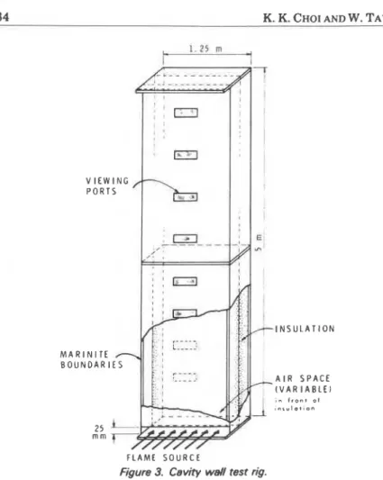
In a study conducted by Taylor [ll], foamed plastics of different flame spread ratings were tested in an apparatus designed to simulate a two-storey wall cavity of mncombustible construction (Figure 3). The objective was to measure the fire spread within the wall cavity, and to determine its dependence on the characteristics of the insula- tion material and the width of air space in the cavity. Flames were in- troduced into the cavity, lined with the insulation materials under test, for 10 min through a 25 mm high horizontal slot located at the bottom of the apparatus. The propagation of fire was observed through a number of viewing ports in the front panel.
When tests were performed with polyurethanes a t air space widths of 12.5 and 15 mm the spread of fire along the insulation was limited to
A I R S P A C E I V A R I A B L E I I n f r o n t .,I l n r u l D t l o n
F L A M E S O U R C E
Figure 3. Cavity well test rig.
1-2 m of the flame source, irrespective of the flame spread rating of the insulation. Increasing the air space to 25 mm resulted in more burning of the foam, although the fire spread was confined to the lower 2 m of the cavity. When the width of the air space was increased to 40 mm. continuous fire propagation throughout the full height of the test assembly was observed. Tests with polystyrenes and an air space of less than 25 mm also revealed very insignificant fire spread; however, melting of the insulation was noted. The molten material flowed down to the bottom of the apparatus, where it was ignited by the flame source and burned as a pool fire. With air gaps of 25 and 40 mm, ven- tilation in the cavity resulted in less melting of the insulation, but in both tests the fire spread to the top of the apparatus.
Combustibility of Insulation in Cavity Walls 185
wall cavities depends on the nature of the foamed plastic, the width of the air space and the ventilation of the cavity. The flame spread rating of the materials used in the tests was not a significant factor. I t is not surprising to find that polyurethane and polystyrene foams behaved
t
quite differently, since the former is a char-forming material while the latter is a thermoplastic that melts on heating before it reaches theC pyrolysis temperature. With masonry-faced cavity walls, glass fiber insulation is still used
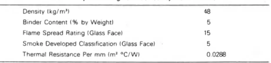
predominantly. Its properties are given in Table 1. The use of this material in buildings of noncombustible construction is not restricted because it has a flame spread rating of less than 25. To determine the validity of using flame spread rating as a measure of the fire spread potential in cavity walls, the fire behaviour of this material was studied. A series of tests using different widths of
air
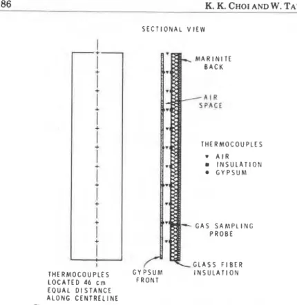
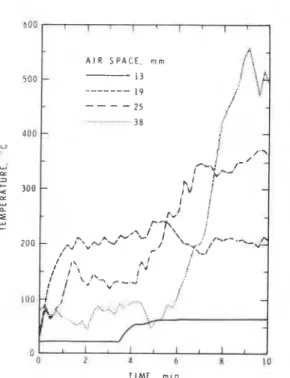
space was per- formed on glass fiber insulation in the same apparatus as that il- lustrated in Figure 3. The test conditions and procedure were identical with those in the earlier study. Because visual monitoring of fire pro- pagation in the cavity can be quite subjective, thermocouples were used to indicate the flame front. The changes in oxygen concentration in the cavity were monitored by sampling gas through a probe situated 1 m above the bottom of the apparatus. Locations of the ther- mocouples and the gas sampling probe are shown in Figure 4.The graph is Figure 5 shows air temperature vs. time as measured by the thermocouple located 2.3 m above the flame source. This level represents a floor-ceiling interface. Obviously, if the spread of fire is to continue from storey to storey, the insulation at the 2.3 m level must be involved in the burning process. In a test with no insulation and an
air space of 25 mm, a mean
air
temperature of 220 OC was measured by the thermocouple a t the 2.3 m level. In tests with insulation a tem- perature rise in excess of 220°C is considered to be caused by addi- tional heat generated by the burning insulation. If burning occurs at this level. the probability of fire spread to the next storey is greatly in- creased. The sudden rise in temperature, 5 min into the tests for air spaces of 25 mm and 38 mm, indicates that propagation of fire beyond the singlestorey height can be expected.The changes of oxygen content in the cavity during tests with dif-
I
Table I . Properties of glass fiber cavity wall insulation.
Dens~ty (kg/rn3) 18
Btnder Content ( % by Weight) 5
Flame Spread Rattng IGlass Face) 15
Smoke Developed C l a s s ~ f ~ c a t ~ o n (Glass Face) 5
186 -
K.
K.
CHOI AND W. TAYLOR S E C T I O N A L V I E WI
i
i
i
i
i
i
i
i
i
I
I
I T H E R M O C O U P L E S L O C A T E D 46 c m E Q U A L D I S T A N C E A L O N G C E N T R E L I N EFigure 4. Location of thermocouples and gas sampling probe.
ferent widths of air space are shown in Figure 6. In these tests, oxygen I
was consumed by the combustion of fuel from the burner a s well a s the
pyrolysis products from the insulation material. The level to which the I
oxygen content dropped depended on how fast the lost oxygen muId
be replenished. In a very narrow air space, the oxygen cannot be
~
replenished rapidly owing to flow restriction. As a result, the oxygen content in the cavity drops to a level where it becomes impossible for the insulation to burn. As the air space is increased. the rate of replenishment increases to the point that the oxygen content in the
cavity reaches a high enough level to support the continuous burning
of the insulation material. As shown in Figure 6, such a transition
takes place when the air space is 25 mm wide.
This
is in agreement with the conclusion derived from temperature-rise measurements.1
The
results of this test series confirm the influence of ventilation on the spread of fire in wall cavities. When the air space is large enough to allow an adequate supply of oxygen for the burning process, the likelihood of fire pmpagation from storey to storey within the wallFigure 5. Air
TIME, man
temperatures measured at 2.3 m from bottom of test apparatus.
TIME rnln
cavities increases greatly, even if insulation of low flame spread rating is used. The critical width of the air space is about 25 rnrn. which agrees with the measurements reported in the tests with poly- urethanes and polystyrenes.
ACKNOWLEDGEMENT
This paper is a contribution from the Division of Building Research, National Research Council of Canada and is published with the a p proval of the Director of the Division.
REFERENCES
1. Davison. J.I.. "Rain Penetration and Masonry Wall Systems," Building Practice Note No. 12. Division of Building Research, National Research Council of Canada, Ottawa (May 1979).
2. Associate Committee on the National Building Code, National Building Code of Canada 1980, NRCC 17303, National Research Council of Canada, Ottawa.
3. ASTM Designation E84-80, "Standard Test Method for Surface Burning Characteristics of Building Materials." Annual Book of ASTM Stan- dards. Philadelphia. Part 18, p. 795 (1980).
4. Williamson, R.B., and Baron, F.M., "A Comer Fire Test to Simulate Residential Fire," Journal of Fire and Flammability, Vol. 4, p. 99 (April 1973).
5. D'Souza. M.V., and McGuire. J.H., "ASTM E-84 and the Flammability of Foamed Thermosetting Plastics," Fire Technology, Vol. 13, p. 85 (May f977).
6. Underwriters' Laboratories of Canada. ULC-S102-1978, "Standard Method of Test for Surface Burning Characteristics of Building Materials." Toronto (1978).
7. Underwriters' Laboratories of Canada. ULC-S102.2-1978, "Standard Method of Test for Surface Burning Characteristics of Flooring, Floor Covering and Miscellaneous Materials," Toronto (1978).
8. McGuire, J.H., and D'Souza. M.V., "Significance of Flamespread Results." Building Research Note No. 137, Division of Building Research, National Research Council of Canada, Ottawa (December 1978).
9. Lie. T.T., "Contribution of Insulation in Cavity Walls to Propagation of Fire." Fire Study No. 29. Division of Building Research, National Research Council of Canada, Ottawa (November 1972).
10. D'Souza, M.V., private communication.
11. Taylor, W., "Fire Spread in Concealed Foamed Plastic Insulation," Fire
T h i s p a p e r , w h i l e b e i n g d i s t r i b u t e d i n r e p r i n t form by t h e D i v i s i o n of B u i l d i n g R e s e a r c h , remains t h e c o p y r i g h t of t h e o r i g i n a l p u b l i s h e r . It s h o u l d n o t be reproduced i n whole o r i n p a r t w i t h o u t t h e p e r m i s s i o n of t h e p u b l i s h e r . A l i s t of a l l p u b l i c a t i o n s a v a i l a b l e from t h e D i v i s i o n may be o b t a i n e d by w r i t i n g t o t h e P u b l i c a t i o n s S e c t i o n , D i v i s i o n o f B u i l d i n g R e s e a r c h , N a t i o n a l R e s e a r c h C o u n c i l o f C a n a d a , O t t a w a , O n t a r i o , KIA 0R6.