HAL Id: hal-02008617
https://hal.archives-ouvertes.fr/hal-02008617
Submitted on 5 Feb 2019HAL is a multi-disciplinary open access
archive for the deposit and dissemination of sci-entific research documents, whether they are pub-lished or not. The documents may come from teaching and research institutions in France or abroad, or from public or private research centers.
L’archive ouverte pluridisciplinaire HAL, est destinée au dépôt et à la diffusion de documents scientifiques de niveau recherche, publiés ou non, émanant des établissements d’enseignement et de recherche français ou étrangers, des laboratoires publics ou privés.
Heterogeneous twinning during directional solidification
of multi-crystalline silicon
J. W. Jhang, Gabrielle Regula, Guillaume Reinhart, Nathalie
Mangelinck-Noël, C. W. Lan
To cite this version:
J. W. Jhang, Gabrielle Regula, Guillaume Reinhart, Nathalie Mangelinck-Noël, C. W. Lan. Heteroge-neous twinning during directional solidification of multi-crystalline silicon. Journal of Crystal Growth, Elsevier, 2019, 508, pp.42-49. �10.1016/j.jcrysgro.2018.12.005�. �hal-02008617�
1
Heterogeneous Twinning during directional solidification of multi-crystalline
silicon
J.W. Jhanga,G. Regulab, G. Reinhartb, N. Mangelinck-Noëlb, C.W. Lana*
a
Department of Chemical Engineering, National Taiwan University, Taipei, 10617,
Taiwan
b
Aix Marseille Univ, Université de Toulon, CNRS, IM2NP, Marseille, France
*Corresponding author: [email protected]; Tel.: 886-2-2363-3917
2
Abstract
Heterogeneous twinning nucleation from the wall or gas interface during
directional solidification of silicon have been modelled, and further used to clarify the
details of twining observed in situ in X-ray synchrotron imaging experiments [1]. It is
found that the heterogeneous twinning from the wall/grains or wall/gas/grain
trijunctions requires much lower undercoolings leading to much higher twinning
probability. The lower attachment energy and the contact area are the key factors for
the heterogeneous nucleation of twins.
Keywords: A1. Twinning; A1. Heterogeneous; A1. Undercooling; A1. Facets; A1.
3
1. Introduction
Twin boundaries in silicon have attracted much attention in recent years due to
their significance in solar cells [1-3]. Most of the twin boundaries in silicon are issued
from 3 twin nucleation on {111} facets [4, 5], which has been studied extensively [6-9]. Among them, the in situ observations through synchrotron X-ray [1-2] have
revealed dynamic features of the twin formation from facets, as well as the defect
formation related to the twinning, during directional solidification of silicon slabs in a
boron nitride crucible. Nevertheless, the role of the crucible wall and of the gas phase
has not yet been understood during twinning. To understand the detailed nucleation
mechanisms, heterogeneous twin nucleation models are necessary.
Duffar and Nadri [10] were the first to extend the Voronkov model [11] to
study twinning during the growth of multi-crystalline silicon (mc-Si). Recently, Lin
and Lan [12] revised this model by considering the interaction between the nucleus
and the neighboring grain. With this modification, referred as Lin’s model, an
estimated undercooling of around 1 K for noticeable twining could be obtained which
is consistent with the literature reported values although slightly higher [13].
Nevertheless, this model showed that the interaction of the nucleus with the
neighboring grains was significant, and the grain boundary (GB) with the twinned
grain on the {111} growth facets was a crucial factor. In addition, Lin and Lan [12]
mentioned that most twin crystals nucleated from the facet-facet groove at the
trijunction (TJ), especially from the non-∑ GBs due to the larger undercooling in the
deeper groove. This model explained the nucleation and twinning mechanism at the
4
explain the more realistic situation of the three-grain tri-junctions (3GTJ) on the
interface during ingot growth, Jain et al. [14], further developed a three-dimensional
model, referred as Jain’s model. With the 3GTJ model, the twinning from certain
grains during mc-Si growth experiments [15] was correctly predicted. More
importantly, the required undercooling for twining was in the order of 0.3 K, which
was consistent with the measured value [2, 13].
In this paper, we extend Jain’s model [14] to the heterogeneous twinning. The
cases involving the wall/grains, wall/gas/grain, and gas/grain junctions are modeled
and discussed. The models are further used to explain the possible twinning locations
characterized during in situ X-ray synchrotron imaging experiments [1, 2]. The
detailed model developed is described in the next section. Section 3 is developed to
results and discussion, followed by conclusions in Section 4.
2. Heterogeneous twinning model
In general, there are several possible heterogeneous twinning situations during
directional solidification observed as well in experiments [1, 2], as summarized in Fig.
1(a), where the schematic of the slab growth is shown on the left figure. As shown,
model 1-1 considers two facets in contact with the crucible wall, so that there is a
wall/G1/G2 TJ and a GB exists between G1 and G2. This model is similar to Jain’s
model by replacing the third grain by the crucible wall. In model 1-2, there is only one
facet in contact with the wall, which occurs on the edge facet. Model 2 takes the gas
phase into consideration. Again, there are two cases for twin nucleation as shown in
5
considers the nucleation from the facet/gas contact line (model 2-2). The force
balances at the junctions for different models are described schematically in Fig. 1(b).
We first consider two facets in contact with the wall (model 1-1), as shown in
Fig. 2. The schematic of the facet and GB planes are shown in Fig. 2(a) and of a
nucleus viewed from the top in contact with the facet, as well as the force balances at
the junctions, are depicted in Fig. 2(b). Again, the nucleus is assumed to be a circular
disc on the facet, as in Jain’s model [14]. Therefore, the angles defined are based on
the view angle normal to the facet, or the angles are normal to the facet. As shown in
Fig. 2(a), each grain contributes with a {111} facet at the TJ, and the facets may not
have the same size. The GB plane is assumed to be parallel to the direction of
solidification, which is generally true for random angle GBs after grain competition
during growth [10]. In addition, the angle could be calculated from the normal vectors of the GB plane and the crucible wall. Again, for the convenience of the
discussion, we assume that the GB is normal to the wall, i.e., = 90o, without losing the generality. In Hurle’s model [16], the first criterion for a facet growth nucleus to
attach at the TJ is that the free energy associated with a step attaching the TJ needs
to be lower than the normal step free energy . Because in the model 1-1, there are
two steps from G1 and G2, the criterion for two steps anchoring at the TJ becomes
, which is similar to Lin’s and Jain’s models. The interaction between a
nucleus step coming from G1 or G2 and the surface of the wall, i.e., the facet-wall
groove, also needs to be considered. Hence, and could be calculated as
6 , (1 ) , (2 ) , (3 )
where is the GB energy. The superscript 1w or 2w indicates the junction between
G1 or G2 and the crucible wall. For silicon, is in the range of 0.45~0.5 J/m2 at
1473 K as reported in the experiments by Otsuki [17]; here we again pick 0.4842 J/m2,
which was a fitting parameter used previously [14]. Also, is the surface free
energy of a {111} plane, and according to Hurle [16] the value is 0.257 J/m2. In
addition, (0.324 nm) is the height of an atomic silicon layer in the direction.
Moreover, (0.473 J/m2) and (0.372 J/m2) are the surface energies at the
wall/solid and wall/melt interfaces, respectively. The facet angles and are the
angle between the facets and the GB plane as shown in Fig. 2(a); and are the
angle between the facets and the wall; the angle is usually not equal to unless
the GB plate is perpendicular to the wall. Once the growth direction is known, e.g., in
direction, in the reference coordinate, the facet angles can be easily
calculated. The grain orientations could be obtained from the Electron Backscatter
Diffraction (EBSD) data.
The next step is to calculate the free energy to create the critical nucleus. The
angle and in Fig. 2(b) can be determined by the force balances at the
7
area for the nucleus on the facet as shown in Fig. 2(c) can be calculated as explained
in [14]. In Fig. 2(c), the angles, normal to the facet, with the superscript prime
indicate they are defined at the top surface of the nuclei. Then, the free energy of
formation for the facet nucleus can be calculated as follows:
, (4) where (5) and . (6)
In Eq. (4), is the entropy of solidification ( J m-3 K-1) and is the
undercooling. and are the area of the surface steps and volume of the
truncated nucleus, respectively; is the area of the edge of the truncated nucleus
between the crucible wall and the nucleus i ( , and is the area of
the edge of the truncated nucleus between G1 and G2.
Figure 3(a) shows the plot of the Gibbs free energy required for the facet
nucleation for an undercooling of 2.8 K with the facet angle ; , and
; .The comparison is also made with Jain’s model [14]. As shown,
the radius of the critical nucleus and the energy barrier in model 1-1 are much smaller than that in Jain’s model. The main reason is that the additional contact energy with the wall ( is much smaller than , which eases nucleation. As a
consequence, the attaching energy in model 1-1 is lower.
8
taken into account, while the facet on G2 keeps the same orientation. Then, the free
energy of formation for a twinned nucleus can be written as:
,
(7)
where is the energy for forming a twin plane at the bottom of the nucleus on G1
and is the bottom contact area of the twin grain nucleus with the parent grain.
Other terms in Eq. (7) are the same as those in Eq. (4). For comparison purposes, we
utilize the twinning energy of 2 mJ/m2 as used in [14]. It should be mentioned that the
twin energy was predicted to be around 20 to 60 mJ/m2 at 0 K for silicon [18].
However, the value is most likely much smaller near the melting temperature (1683 K)
as the examples discussed in [14]. Moreover, the Gibbs free energy for twin
nucleation is plotted in Fig. 3(b). As shown, both the Gibbs free energy and the
critical radius for twin nucleation are higher than that for facet growth studied above. As compared with Jain’s model, the twin nucleation is easier because of the additional contribution from the wall. After the free energy barriers of formation for the faceted
and twinned nuclei are obtained, we can further calculate the twinning probability
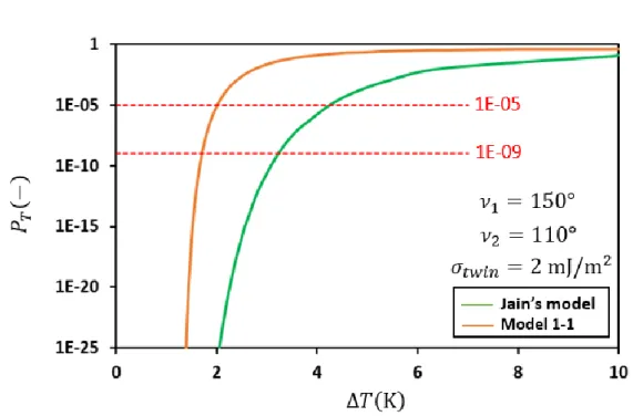
according to [10] as: , (8)
where and are the free energy barriers for facet and twin nucleation,
respectively; is the Boltzmann constant. The twinning probability as a function of
the undercooling is shown in Fig. 3(c), where the probability based on Jain’s model is
9
higher than that in Jain’s model for all undercooling.
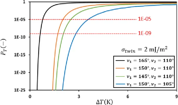
The effect of the facet angles ( and ) on the twinning probability has been
further studied and data are gathered in Fig. 4. As shown, with a larger facet angle, for
a given twinning probability, the required undercooling is smaller. Again, this is due
to the effect of the angle on the truncated volume and of the smaller . As
shown in Fig. 4, with and , the critical undercooling for frequent
twin nucleation ( is around in model 1-1, and this
undercooling is consistent with the value estimated from the experiments ( )
[13].
Model 1-2 is a simplified case of model 1-1, which is shown in Fig. 1(a) for
the facet at the edge. Because there is only one facet in contact with the wall, the free
energy associated with a step attaching the junction, the free energies of
formation for the faceted and twinned nucleus can be calculated as follows:
, (9) , (10) . (11)
Similarly, the twinning probability for different undercoolings could also be
calculated. For the same angle, e.g. =110o, the required undercooling for twining is
about 5 to 6 K for model 1-2 having a probability of 10-5 as compared to 2 K in model
1-1. Similarly for the same undercooling , the twinning probability increases as the
facet angle increases. Again, this is due to the smaller attaching energy and to the
10
Next we consider the wall/grain/gas trijunction (model 2-1) as presented in Fig.
1 for the facet at the edge. Similarly, the criterion for the occurrence of facets at the
junction is that the free energies and associated with a step attaching the
junction needs to be lower than the normal step free energy. Thus, the attaching
energies , , and the free energies of formation for the faceted and twinned
nuclei can be written as:
, (12) , (13) , and (14) , (15)
where the facet angle is the angle between the facet and the gas, and (0.604
J/m2) and (0.75 J/m2) are the gas/crystal and gas/melt interfacial energies,
respectively; and are the edge areas of the truncated nucleus on the wall
and gas sides, respectively. For =110o, =60o, and =50o
, the required
undercooling for twining is about 3.2 K for model 2-1 having a probability of 10-5 as
compared to 2 K in model 1-1; the contact angle is the angle between the crystal
edge and the wall. Similar to the previous cases, the twinning probability increases
with the increasing facet angles due to the lower attaching energy and to the lower
11
decreases, the twinning probability increases as a result of the lower contact area.
Model 2-2 is a simplified case of model 2-1, which considers the nucleation
from the facet/gas contact line as shown in Fig. 1. The free energy associated with
a step attaching the junction, the free energy of formation for the faceted and twinned
nucleus can be formulated as follows:
, (16) , (17) and . (18)
The twinning probability curves with the effect of the facet angle as a function
of the undercooling are similar to model 2.1, but the undercooling is about 1.5 K
higher for the similar angles, i.e., . Again, the higher facet angle leads to
the higher twinning probability due to the smaller attaching energy and lower
contact area.
3. Results and discussion
To validate our models, three cases from the experiments developed by the
IM2NP team [1, 2, 19] are selected for comparison. We first consider one experiment
of growth from a seed oriented <100> in the solidification direction and presented in
details in [2, 19]. The EBSD map of the final grain structure is shown in Fig. 5(a). For
this experiment, two cases labeled as Cases 1 and 2 are considered. The Case 1
12
shown by the in situ X-ray imaging during this experiments, the 3 twin grain (purple on the inverse pole figure EBSD map Fig. 5) nucleates on the {111} facet of
G1 in the grain boundary groove, instead of the one of G2. The enlarged figure of
Case 1 is shown in Fig. 5(b), while Case 2 in Fig. 5(c). The evolution of a typical
facetted/facetted groove at the solid-liquid interface during directional solidification
in the same experiment was described by Stamelou et al. [2]. With a sufficient
undercooling, a twin grain can nucleate on one of the facets. However, there are two
possibilities for this twinning: at the G1/G2 GB away from the wall or at the
G1/G2/wall TJ. For the former case, Lin’s 2D model [12] is a proper one to apply
because the bisector rule could be adopted for Case 1. However, for the latter, we
need to apply model 1-1. To predict the correct site for twin nucleation, we need to
compare the twinning probability of both models under the same undercooling.
The corresponding Euler angles of G1 (parent grain), G2 and twin grain
obtained from EBSD are listed in Table 1(a). The eight [111] vectors of each grain
could be obtained from its Euler angles, and so as the corresponding facet angles
and shown in Fig. 2(a). Again, we assume the GB angle to be in
the calculation, and the GB energy ( ) is chosen to be 0.48 J/m2 [12]. With the facet
angles and , the attaching energies could be calculated as described previously.
The corresponding facet angles and the attaching energy values associated with facet
1 and facet 2 of model 1-1 and 2D nucleation model are listed in Table 1(b) and (c),
respectively. It can be seen that for both facets of model 1-1, the attaching energy to
the nucleus/grains/wall TJ is negative and that for facet 1, it is slightly lower due to
13
twinned nucleus for both facets for model 1-1 are significantly lower than Lin’s 2D
model with the observed undercooling (T = 0.35 K), and the critical radius of the
twin nucleus is about 2.1 nm.
The energy barrier for the twining on facet 1 of model 1-1 turns out to be the
lowest; the barrier for facet 2 should be the same if the bisector rule is applied.
Accordingly, the twinning probability ( ) is the highest in the three situations.
The contact area and probability of twinning calculated by both models for Case 1 are
listed in Table 1(d). As shown, beside the probability, the corresponding contact area
of the nucleus on facet 1 is also the lowest one. Because the twin energy term is the
lowest, the twinning is more likely to occur at facet1/GB/wall TJ. On the contrary,
with the undercooling of 0.35 K, we could not find an energy barrier of twinning on
the facet based on Lin’s 2D model within a reasonable nucleus size, so that the
twinning is not likely. Therefore, we could conclude that for Case 1 the twinning on
facet 1 at the G1/GB/wall TJ is the most thermodynamically favorable at the
measured undercooling, and this is consistent with the experimental result.
For Case 2 in Fig. 5(c), the twin formation from both facets appear at
the edges of the solid-liquid interface. For this case, we focus on the twinning
phenomenon on the left hand side of the graph and test model 2-1 (facet/gas/wall TJ)
or model 2-2 (facet/gas contact line) for predicting the twinning probability. The
corresponding Euler angles of the parent (G1) and twin grains are also obtained from
EBSD data, as listed in Table 2(a). The corresponding facet angles could then be
calculated as presented in Table 2(b). We set the angle to be for model 2-1 for
14
the attaching energy values, contact area and twinning probabilities associated with
the {111} facet are calculated and listed in Table 2(c) and (d). It can be seen that the
facet of model 2-1 has a positive value, which would increase the energy barrier
of formation for a twinned nucleus, but the bottom contact area of the nucleus in
model 2-1 is much lower than that in model 2-2. In addition, the contribution of the
twin energy is also lower to the energy barrier of twinning on the facet in model 2-1.
As a result, the energy barrier for twinning from model 2-1 is slightly lower, but the
difference is quite small. The critical radius for twinning is 22 nm for model 2-1 and
23 nm for model 2-2 at an undercooling of 4 K. Thus, the twinning at the
facet/gas/wall TJ is more likely than that at the facet/gas contact line. The
undercooling in the model needs to be higher (4 K). In the experiments [2], the
undercooling at the edge is indeed higher than in the grain boundary grooves and this
is revealed by the larger facets observed. However, the measured values were always
lower than 1 K which implied that twin nucleation occurred before an undercooling of
4 K was reached. It could also mean that an additional mechanism eases nucleation as
the presence of defects on the {111} facet such as dislocations and/or the presence of
impurities.
The last case is shown in Fig. 6, where the EBSD map in Fig. 6(a) is from [1]
and the area inside the box is labeled as Case 3 in the following. The schematic of the
twin formation during crystal growth is illustrated in Fig. 6(b), where the twin grain
appears form the left and continues to grow to the right. For this case, the twin could
nucleate from facet/wall contact line (model 1-2) or from facet/gas/wall TJ (model
15
also obtained by EBSD and summarized in Table 3(a) and the calculated facet angles
for both models are listed in Table 3(b); the angle in model 2-1 is assumed to be
in the calculation.
The attaching energy values, contact area and twinning probability associated
with the facet in both models are listed in Table 3(c) and (d). It can be seen that model
2-1 has a negative attaching energy, which would help to decrease the energy barrier
for twinning. In addition, the bottom contact area of the nuclei in model 2-1 is lower
than that in model 1-2, so that the contribution of twin energy is also lower to the
nucleation barrier in model 2-1. The energy barrier for the twin nucleation from the
facet/gas/wall TJ (model 2-1) is indeed lower than that from the facet/gas junction
(model 2-2); the undercooling is set at 2.6 K. The critical radius for twining is 47 nm
at the facet/gas/wall TJ, which is only half of that at the facet/gas contact line. The
twinning probability in Table 3(d) further indicates that the twinning from the
facet/gas/wall TJ is more favorable as also demonstrated for the same situation in Fig.
5.
4. Conclusions
In this study, the 3GTJ model proposed by Jain et al. [14] is extended to the
heterogeneous twinning considering the wall and gas boundaries; the models are
developed for the wall/grains/GB, wall/grain, wall/gas/grain, and gas/grain TJs. It is
observed that the radius of critical truncated nucleus and the energy barrier in model
1-1 (wall/G1/G2 TJ) are much smaller than that in Jain’s 3GTJ model. The models are
16
good agreement including the predicted undercooling. It is found that twin grain
nucleation probability is higher at the edge of the sample and/or at the crucible walls,
where the attaching energy and the bottom contact area of the twin nucleus tend to be
lower which is as well in nice agreement with what is generally observed during
directional solidification.
Acknowledgement
This work was supported by the Ministry of Science and Technology of Taiwan
for the group in Taiwan and by the French National Research Agency (ANR) with Project CrySaLID (No ANR-14-CE05-0046-01). The collaboration between both groups was sustained in both countries by the PhD ORCHID framework (project No
35898SB).
References
[1] M.G. Tsoutsouva, T. Riberi-Beridot, G. Regula, G. Reinhart, J. Baruchel, F. Guittonneau, L. Barrallier, N. Mangelinck-Noel, In situ investigation of the structural defect generation and evolution during the directional solidification of < 110 > seeded growth Si, Acta Mater. 115 (2016) 210-223.
[2] V. Stamelou, M.G. Tsoutsouva, T. Riberi-Beridot, G. Reinhart, G. Regula, J. Baruchel, N. Mangelinck-Noel, {111} facet growth laws and grain competition during silicon crystallization, J. Cryst. Growth 479 (2017) 1-8.
[3] H.J. Moller, C. Funke, M. Rinio, S. Scholz, Multicrystalline silicon for solar cells, Thin Solid Films 487(1-2) (2005) 179-187.
[4] K. Nagashio, K. Kuribayashi, Growth mechanism of twin-related and twin-free facet Si dendrites, Acta Mater. 53(10) (2005) 3021-3029.
[5] C.I. Drowley, G.A. Reid, R. Hull, Model for facet and sidewall defect formation during selective epitaxial-growth of (001) silicon, Appl. Phys. Lett. 52(7) (1988) 546-548.
17
epitaxial regrowth rate from Si-implanted amorphous Si, Appl. Phys. Lett. 49(7) (1978) 3906-3911.
[7] C.W.T. Bulle-Lieuwma, A.H. van Ommen, L.J. van IJzendoorn, Microstructure of heteroepitaxial Si/CoSi2/Si formed by Co implantation into (100) and (111) Si,
Appl. Phys. Lett. 54(3) (1989) 244-246.
[8] A. Bourret, J.J. Bacmann, Atomic-structure of grain-boundaries in semiconductors Studied by electron-microscopy (analogy and differences with surfaces), Surf. Sci. 162(1-3) (1985) 495-509.
[9] A. Garg, W.A.T. Clark, J.P. Hirth, Dissociated and faceted large-angle coincident-site-lattice boundaries in silicon, Philos.. Mag A 59(3) (1989) 479-499.
[10] T. Duffar, A. Nadri, On the twinning occurrence in bulk semiconductor crystal growth, Scripta. Mater. 62(12) (2010) 955-960.
[11] V. V. Voronkov, Processes at the boundary of a crystallization front, Sov. Phys . Crystallogr. 19 (1975) 573-577.
[12] H.K. Lin, C.W. Lan, Revisiting the twinning mechanism in directional solidification of multi-crystalline silicon sheet, Acta Mater. 131 (2017) 1-10. [13] A. Tandjaoui, N. Mangelinck-Noel, G. Reinhart, B. Billia, T. Lafford, J.
Baruchel, Investigation of grain boundary grooves at the solid-liquid interface during directional solidification of multi-crystalline silicon: in situ characterization by X-ray imaging, J. Cryst. Growth 377 (2013) 203-211.
[14] T. Jain, H.K. Lin, C.W. Lan, Twinning mechanism at three-grain tri-junction during directional solidification of multi-crystalline silicon, Acta Mater. 144(Supplement C) (2018) 41-50.
[15] Y.T. Wong, C. Hsu, C.W. Lan, Development of grain structures of multi-crystalline silicon from randomly orientated seeds in directional solidification, J. Cryst. Growth 387 (2014) 10-15.
[16] D.T.J. Hurle, A Mechanism for Twin Formation during Czochralski and encapsulated vertical bridgman growth of III-V compound semiconductors, J. Cryst. Growth 147(3-4) (1995) 239-250.
[17] A. Otsuki, Energies of (001) twist grain boundaries in silicon, Acta Mater. 49(10) (2001) 1737-1745.
[18] R. Hull, INSPEC, Properties of crystalline silicon, INSPEC, the Institution of Electrical Engineers, 1999.
[19] Thècle Riberi-Béridot, In situ characterization by X-ray synchrotron imaging of the solidification of silicon for the photovoltaic applications: control of the grain structure and interaction with the defects and the impurities, PhD Thesis, Aix Marseille Univ (2017).
Table Captions:
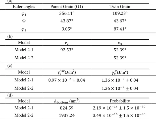
Table 1 (a) The corresponding Euler angles of parent grain (G1), G2 and twin grain;
(b) the corresponding facet angles; (c) the attaching energy values associated
with both {111} facets for model 1-1 and for 2D nucleation model; (d) the
contact area ( ) and the probability of twinning calculated by model 1-1
and 2D nucleation model for Case 1.
Table 2 (a) The corresponding Euler angles of parent grain (G1) and twin grain; (b)
the corresponding facet angles; (c) the attaching energy values associated with
a {111} facet for models 2-1 and 2-2; (d) the contact area ( ) and
probability of twinning calculated by models 2-1 and 2-2 for Case 2.
Table 3 (a) The corresponding Euler angles of parent grain (G1) and twin grain; (b)
the corresponding facet angles; (c) the attaching energy values associated with
a {111} facet for models 1-2 and 2-1; (d) the contact area ( ) and
probability of twinning calculated by models 1-2 and 2-1 for Case 3.
Table 1 (a) The corresponding Euler angles of parent grain (G1), G2 and twin grain;
(b) the corresponding facet angles; (c) the attaching energy values associated with
both {111} facets for model 1-1 and for 2D nucleation model; (d) the contact area
( ) and the probability of twinning calculated by model 1-1 and 2D nucleation
model for Case 1.
(a)
Euler angles Parent Grain (G1) G2 Twin Grain (b) Model Model 1-1 Facet 1 Model 1-1 Facet 2 2D nucleation model (c) Model (J/m2) (J/m2) (J/m2) Model 1-1 Facet 1 Model 1-1 Facet 2 2D nucleation model (d) Model (nm2) Probability Model 1-1 Facet 1 Model 1-1 Facet 2 2D nucleation model Table 1
Table 2 (a) The corresponding Euler angles of parent grain (G1) and twin grain; (b)
the corresponding facet angles; (c) the attaching energy values associated with a
{111} facet for models 2-1 and s2-2; (d) the contact area ( ) and probability of
twinning calculated by models 2-1 and 2-2 for Case 2.
(a)
Euler angles Parent Grain (G1) Twin Grain (b) Model Model 2-1 Model 2-2 (c) Model (J/m2) (J/m2) Model 2-1 Model 2-2 (d) Model (nm2) Probability Model 2-1 Model 2-2 Table 2
Table 3 (a) The corresponding Euler angles of parent grain (G1) and twin grain; (b)
the corresponding facet angles; (c) the attaching energy values associated with a
{111} facet for models 1-2 and 2-1; (d) the contact area ( ) and probability of
twinning calculated by models 1-2 and 2-1 for Case 3.
(a)
Euler angles Parent Grain (G1) Twin Grain (b) Model Model 1-2 Model 2-1 (c) Model (J/m2) (J/m2) Model 1-2 Model 2-1 (d) Model (nm2) Probability Model 1-2 Model 2-1 Table 3
Figure Captions:
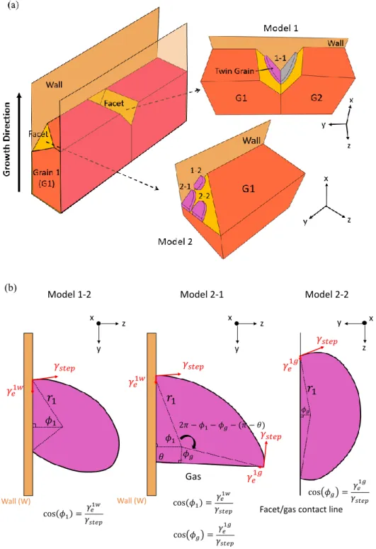
Fig. 1 (a) Schematic of the possible heterogeneous twinning sites; (b) schematic for force balances at the TJ’s for model 1-2, model 2-1 and model 2-2.
Fig. 2 (a) The facet-facet/wall groove; (b) the top view of the nucleus and the force balances required at the TJ’s; (c) the final shape of the truncated nucleus on facet 1 for model 1-1. In Fig. 2(c), the angles, normal to the facet, with the
superscript prime indicate they are defined at the top surface of the nucleus.
Fig. 3 (a) Free energy of formation for a faceted nucleus with a facet angle
for an undercooling of 2.8 K in both models; J/m2;(b)
free energy of formation for a twinned nucleus with a facet angle
for an undercooling of 2.8 K in both models; J/m2 and
mJ/m2;(c) twinning probability at the facet angle as a
function of the undercooling at J/m2 and mJ/m2.
Fig. 4 Effect of the facet angles on the twinning probability as a function of the
undercooling for model 1-1 with 2 mJ/m2
.
Fig. 5 (a) EBSD IPF (Inverse Pole Figure) map along the growth direction of the
grain structure after growth from a seed oriented <100> from the experiment
described in details in [2, 19] ; (b) zoom in a region of twin nucleation
corresponding Case 1 (grain boundary groove); (c) zoom in a region of twin
nucleation corresponding Case 2 (edge {111} facet).
Fig. 6 (a) EBSD IPF (Inverse Pole Figure) map along the growth direction of the grain
structure after growth from a seed oriented <110> from the experiment
described in details in [1]. Twin grain growth from SLG TJ (Case 3); (b)
schematic showing the twin formation at the solid-liquid interface during
Fig. 1 (a) Schematic of the possible heterogeneous twinning sites; (b) schematic for force balances at the TJ’s for model 1-2, model 2-1 and model 2-2.
Fig. 2 (a) The facet-facet/wall groove; (b) the top view of the nucleus and the force balances required at the TJ’s; (c) the final shape of the truncated nucleus on facet 1 for model 1-1. In Fig. 2(c), the angles, normal to the facet, with the superscript prime
indicate they are defined at the top surface of the nucleus.
Fig. 3 (a) Free energy of formation for a faceted nucleus with a facet angle
for an undercooling of 2.8 K in both models; J/m2;(b)
free energy of formation for a twinned nucleus with a facet angle
for an undercooling of 2.8 K in both models; J/m2
and
mJ/m2;(c) twinning probability at the facet angle as a
function of the undercooling at J/m2 and
Fig. 4 Effect of the facet angles on the twinning probability as a function of the
undercooling for model 1-1 with 2 mJ/m2.
Fig. 5 (a) EBSD IPF (Inverse Pole Figure) map along the growth direction of the
grain structure after growth from a seed oriented <100> from the experiment
described in details in [2, 19] ; (b) zoom in a region of twin nucleation
corresponding Case 1 (grain boundary groove);(c) zoom in a region of twin
nucleation corresponding Case 2 (edge {111} facet).
Fig. 6 (a) EBSD IPF (Inverse Pole Figure) map along the growth direction of the grain
structure after growth from a seed oriented <110> from the experiment
described in details in [1]. Twin grain growth from SLG TJ (Case 3);(b)
schematic showing the twin formation at the solid-liquid interface during
directional solidification for Case 3.


![Fig. 6 (a) EBSD IPF (Inverse Pole Figure) map along the growth direction of the grain structure after growth from a seed oriented <110> from the experiment described in details in [1]](https://thumb-eu.123doks.com/thumbv2/123doknet/14666796.741005/31.892.191.698.217.606/inverse-figure-direction-structure-oriented-experiment-described-details.webp)