HAL Id: hal-01086078
https://hal.archives-ouvertes.fr/hal-01086078
Submitted on 13 Feb 2015
HAL is a multi-disciplinary open access
archive for the deposit and dissemination of
sci-entific research documents, whether they are
pub-lished or not. The documents may come from
teaching and research institutions in France or
abroad, or from public or private research centers.
L’archive ouverte pluridisciplinaire HAL, est
destinée au dépôt et à la diffusion de documents
scientifiques de niveau recherche, publiés ou non,
émanant des établissements d’enseignement et de
recherche français ou étrangers, des laboratoires
publics ou privés.
Multi-physic system simplification method applied to a
helicopter flight axis active control
Mikaël Martin, Julien Gomand, François Malburet, Pierre-Jean Barre
To cite this version:
Mikaël Martin, Julien Gomand, François Malburet, Pierre-Jean Barre. Multi-physic system
simplifi-cation method applied to a helicopter flight axis active control. Multi-Physic System Simplifisimplifi-cation
Method Applied to a Helicopter Flight Axis Active Control, Nov 2012, Penang, Malaysia. pp.274
-279, �10.1109/ICCSCE.2012.6487155�. �hal-01086078�
Science Arts & Métiers (SAM)
is an open access repository that collects the work of Arts et Métiers ParisTech
researchers and makes it freely available over the web where possible.
This is an author-deposited version published in: http://sam.ensam.eu
Handle ID: .http://hdl.handle.net/10985/8963
To cite this version :
Mikael MARTIN, Julien GOMAND, François MALBURET, Pierre-Jean BARRE - Multi-physic system simplification method applied to a helicopter flight axis active control - In: Multi-Physic System Simplification Method Applied to a Helicopter Flight Axis Active Control, Malaysia, 2012-11-23 - Control System, Computing and Engineering (ICCSCE) - 2012
Any correspondence concerning this service should be sent to the repository
Multi-Physic System Simplification Method Applied to a Helicopter
Flight Axis Active Control
Mikaël MARTIN
Arts et Metiers ParisTech ; CNRS, LSIS Aix en Provence, France (Fr) e-mail: mikael.martin-7@etudiants.ensam.eu
François MALBURET
Arts et Metiers ParisTech ; CNRS, LSIS Aix en Provence, France (Fr) e-mail: françois.malburet@ensam.eu
Julien GOMAND
Arts et Metiers ParisTech ; CNRS, LSIS Aix en Provence, France (Fr) e-mail: julien.gomand@ensam.eu
Pierre-Jean BARRE
Arts et Metiers ParisTech ; CNRS, LSIS Aix en Provence, France (Fr) e-mail: pierre-jean.barre@ensam.eu
Abstract— A helicopter flight axis control, which is a complex
multi-physic system, is modelled using an energetic based graphical tool: the Energetic Macroscopic Representation. Elements of the system are mainly composed of passive technologies and their number tends to increase year after year to improve the pilots comfort by adding new functions. A new methodology is proposed to transform the system into a new active one by replacing some hydro-mechanical elements by a new controllable active mechanical source. The challenge is to simplify the flight control architecture while preserving the global behaviour of the system.
Index Terms—Energetic Macroscopic Representation,
modelling, control, Internal Model Reference, Helicopter
I. INTRODUCTION
From the first flight in 1903 of Wright Flyer in Kitty Hawk (US) to the last new technology ones, aircrafts have been equipped with mechanical and hydro-mechanical actuators for flight control. Over time, designers have increased the number of elements of each flight axis control to improve pilots comfort. However, mechanical and hydro-mechanical systems are relatively heavy, difficult to adjust and without possibilities of evolution. They also have limited dynamic capabilities compared to electromechanical systems but are able to provide higher forces.
Following that general and inevitable evolution, helicopters became complex systems as they are composed of numerous subsystems, involving many physical domains (mechanics, hydraulics, electronics, aerodynamics…). The matter of this paper is to present a new methodology which aims to help engineers designing new architectures. More specifically, it concerns complex systems which have to be improved or simplified by substituting passive elements for active technologies. The challenge is to preserve the global behaviour of the passive system. A helicopter flight axis control is described in this paper to illustrate the methodology. Specific graphical approaches can be used to help in modelling and controlling multi-physic systems [1]. They offer specific powerful unified modelling formalisms to simplify complex multi-physics system analysis. The
methodology presented in this paper is based on the Energetic Macroscopic Representation which brings a global overview of the system. The first section is devoted to the energetic description of the helicopter flight axis control. The second section presents the methodology to transform the system composed of passive elements into an active one. Simulation results using Matlab/Simulink finally validate the proposed methodology.
II. MULTI-PHYSICS SYSTEM MODELLING USING ENERGETIC GRAPHICAL DESCRIPTION
This section is dedicated to a helicopter axis control modelling. The main elements which contribute to the functioning of helicopter rotor blades pitch control are introduced. A lumped parameter model of an independent and simplified axis control is deduced. Using an energetic graphical description, a model organisation is proposed to highlight power transfers and energy storages.
A. Studied system description
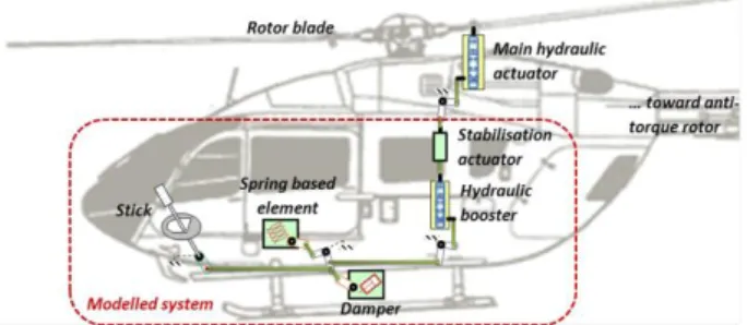
Helicopter pilots initially had to control the rotor blades pitch through four direct mechanical control chains, without any assistance. Each axis corresponded to an independent flight axis: Pitch and Roll axes are dedicated to control the cyclic rotor swachplate angles (forward and lateral directions), while the collective axis is linked to the rotorcraft power (correlated to acceleration and speed), and the Yaw axis acts as an anti-torque (that of the main rotor) control through the tail rotor. With the increase of the aircraft size, and thus their mass increase, irreversible hydraulic powered assistance actuators (see, Fig. 1) became necessary to provide enough force and control rotor blades pitch. This way, pilots workload is significantly reduced: they only provide a low level of force to control the hydraulic actuators control input.
This leads to one drawback: the force feedback provided to the pilots is constant whatever the rotor blades pitch are. Spring based elements (see Fig.1) mounted in parallel with the flight controls have been necessary to provide a feedback proportional to the control stick deviation with regard to its initial position.
Fig. 1. Helicopter flight axis control, a multi-physical system
High dynamic control movements are forbidden to preserve the stability and the integrity of the helicopter. To prevent from pilots unintentional high dynamic stick movements and to damp the pilot’s actions, mechanical dampers (see Fig. 1) are also placed in parallel with the control mechanical chains. The residual forces due to the presence of multiple rods, bell cranks and ball bearings generate undesired friction forces between stick controls and main hydraulic actuators. In order to improve pilots comfort, an additional irreversible hydraulic assistance (see, Fig. 1) has been introduced into each flight axis control.
For the sake of security, a fast stabilisation actuator (see Fig. 1) with low stroke capabilities has been introduced in series with each flight control in order to correct small deviations of the helicopter from its set point.
In the following, the considered system is part of one helicopter flight axis control, from the stick to the stabilisation actuator, described in previous part and highlighted in Fig. 1. Part of this control chain has already been represented in [2], highlighting two energetic subsystems: the first one is composed of the stick, the damper and the spring based element; it is dedicated to create a stick force feedback and to control the power of the second energetic system through the control of the hydraulic booster valve. The second energetic subsystem is the remaining part of the flight axis control: it creates the adequate force to control the rotor blade pitch angles from a given set point imposed by the hydraulic booster valve. The valve, which is the link between the two energetic systems, represents an energetic break in the flight axis control. In [2], the aim was to remove the spring based element and to replace it by an active force feedback electromechanical system. The force feedback reference which is function of the stick position was obtained by empirical method comparing both systems. In this paper, a method has been carried out to determine from the actual process the reference to be applied on the active system. This method is verified on the entire process: other elements such as the hydraulic booster than the spring based element are removed. As a consequence, the two energetic subsystems will not be independent anymore. The entire representation of the flight axis control is therefore required to consider the interaction between these two subsystems.
The main purpose of this section is to obtain an energetic graphical description of the entire flight axis control. The first step consists in a structural analysis of the control chain, leading to a lumped parameter model.
B. Energetic description
Bond Graph (BG) [4]-[5] and Energetic Macroscopic Representation (EMR) [6] are both graphical and energetic oriented tools which simplify the analysis of complex multi-physic systems. A complementary approach between BG and EMR is dealt in [7]. Both of them represent energy flows in the system highlighting the power exchanged between each component. Whereas BG defines a bidirectional connection (power bond) between two components, the more recent energetic tool EMR describes power exchanges through bidirectional connection bringing out the effort and flow state variables.
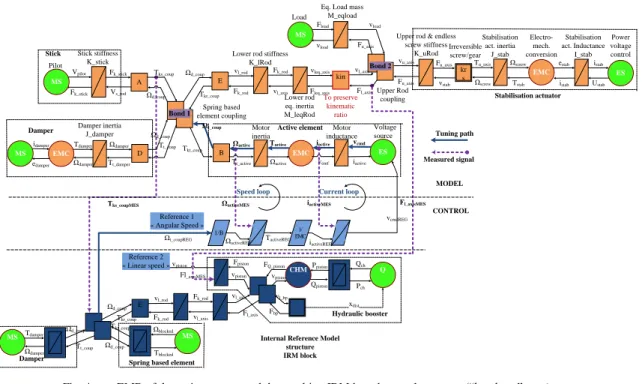
EMR is a control oriented tool: it describes physical process imposing natural integral causality contrary to BG which allows a mathematical derivative description of physical accumulative processes. Integral causality representation makes thereafter easier the design of control architectures using a systematic model based inversion methodology. A large part of our researches are focused on the control of an active element justifying why EMR has been adopted. Fundamental energy processes are defined by simple specific elements. Depending on their power function, four main types of elements can be distinguished: energy sources and accumulation elements, conversion elements (without energy accumulation), and coupling elements for energy distribution. Based on equations of below section II.C and from [2], the EMR of the studied helicopter flight axis control is given in Fig. 3.
C. Flight axis control chain modelling
1) From stick to hydraulic assistance control valve
Main characteristics of this first part of the model (lower left part of Fig. 3) are mathematically defined and represented in [2]. The stick is mainly characterised by the stiffness Kstick which is nearly half of the total flight axis stiffness. The stick force feedback is mainly provided by a physical rotational spring Kspring in the case of the spring based element configuration. The damper is composed of multiple gear boxes assimilated to a single equivalent inertia, Jdamper. The mechanical link between the spring based element and the input of the hydraulic actuator is assimilated to a spring/mass system (Kl_rod, Ml_axis), see mathematical equations in (1). The last element of this first control chain part is the hydraulic assistance actuator control valve which is directly linked to the stick displacement. This valve is assimilated to a mass/spring system (Mvalve, Kvalve).
_ _ _ _ 0 _ _ _ _ 0 1 tk rod l rod l rod l axis t
l axis k rod l axis l axis F t K v T v T dT v t F T F T dT M
(1) 2) Hydraulic assistanceThe hydraulic actuator is represented as an energy transformer (from hydraulic energy into mechanical work. A model of a hydraulic actuator is described in [3], including the effects of servo-valve dynamics and fluid compressibility. A simplex hydraulic system with two symmetrical chambers is
Load Return pressure Damper Piston coupling Spring based element coupling Stick stiffness K_stick Fluid compressibility Hydro-mechanical conversion Lower rod stiffness K_lRod spring K_spring Pilot Ωd_coup Tkt_coup vkt_spring Fk_spring vl_bp Fbp Fu_axis vpiston Load mass M_load vload Fload vgearBox Fk_spring Ωd_coup Tks_coup Vs_rod Fk_stick Vpilot MS A B E Tkr_coup Ωd_coup F vl_axis Fk_rod vl_valve Fvalve vlr_byp Fbp Bypass coupling G H Fbp vpr_bp Fbp_piston vpiston HMC FQ_piston vpiston Ppiston Qpiston Qch1 Pch1 Qch1 Pch1 Ps Fpiston vpiston EMC Kt_stab MS ES Fk_rod vl_rod Fk_stick Damper inertia J_damper D Ωd_coup Tt_coup EMC Ωdamper Tdamper MS edamper idamper Tt_damper Ωdamper vu_axis Fu_axis Ωscrew Tstab Electro-mech. conversion Tu_axis Ωscrew Power voltage control Stabilisation act. inertia J_stab istab estab vload Fu_axis
Upper rod & endless screw stiffness K_uRod Upper Rod coupling vl_axis Lower rod inertia M_lRod Fl_axis MS Stabilisation act. Inductance I_stab Ustab istab Hydraulic assistance
Spring based element Damper Stick Stabilisation actuator Tblocked Ωblocked Motor control MS kr s krt Right-angle Gear box Fvalve vu_valve Valve stiffness Valve mass
vu_valve Fext_dist Pchamber1 Pch2 Qpiston Qpiston Qch2 Pch2 Qch1 Pch1 Qch2 Pch2 Qch2 Pch2 Pr Ps Ps Pr Pr Pr Qch1 Qr Qch2 Qch1 Qch2 Ps Qs Pressure source I11 I12 I21 I22 vu_valve ud ud ud ud Fu_axis vstab Irreversible screw/gear Piston mass M_piston
Fig. 3 Energetic Macroscopic Representation of a Helicopter flight axis control (“hands on” case)
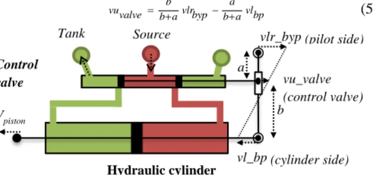
considered. Hydraulic pressure losses are supposed to be insignificant. The control valve routes the fluid from the hydraulic source at pressure Ps to one chamber and links the second one to the return tank (Pr) (Fig. 2). The corresponding equations matching the fluid flow (Q1, Q2) and the pressure (P1, P2) of each chamber depending on the position of the control valve ud are summarised in (2). kd [kg/m] is a positive constant which characterises an hydraulic control valve.
( 1) 1 if 0 1 ( 1 ) 1 P if r 0 ( 2 ) 2 if 0 2 ( 2) P 2 if 0 k u Sgn Pd d s P Ps Pch ud Qch k u Sgn Pd d ch Pr Pch ud k u Sgn Pd d ch Pr Pch Pr ud Qch k u Sgn Pd d s Pch Ps ch ud (2)
The dynamic behaviour of the piston depends on pressure evolution in both chambers. The pressure variation inside one chamber is proportional to the difference between input and output flows and to the variation of the chamber volume. If leakage flows are neglected and if the actuator is symmetrical (meaning the useful surface of both chambers is the same and equal to S), the compressibility (βe) dynamic equations of the
pressures in both chamber are given in (3). V0 is the hydraulic cylinder dead volume; upiston and vpiston are respectively the position and the speed of the hydraulic cylinder. The variations of fluid flows in both chambers make the piston moving. The corresponding hydro-mechanical conversion is given by equations (4).
1 1 0 0 2 2 0 0 t e P t Q T S vpistonT dT V S upistonT t e P t Q T S vpistonT dT V S upistonT (3)
1 2
Fpiston S P P Qpiston S vpiston (4)The hydraulic assistance is associated with a mechanical position regulating loop (Fig. 2): The valve position is mechanically linked to both the control chain from the pilot side, with speed vlr_byp and from the hydraulic cylinder speed
vl_bp so as to ensure a piston displacement proportional to the
control input whatever the load on the piston is. The kinematic equation of the mechanism is given by (5), where a and b are rod lengths: b a vuvalve vlrbyp vlbp b a b a (5) Tank (Pr) Source pressure (Ps) Control valve Hydraulic cylinder
vlr_byp (pilot side)
vl_bp (cylinder side) vu_valve (control valve)
Vpiston b
a
Fig. 2. Hydraulic assistance mechanical position regulating loop principle 3) Stabilisation actuator
The stabilisation actuator (upper right part of Fig. 3) is introduced in series in flight control architecture. Stabilisation process consists in driving the position of the output shaft actuator with regard to the helicopter attitude, measured through inertial data centres. The position reference is provided by the Auto Pilot Module (APM) to the stabilisation actuator which is then self-monitored (current and speed loops). The actuator mainly consists of a motor inertia Jstab, an inductance
Lstab and an irreversible gear box (6). The ball-screw stiffness is included in the stiffness Ku_rod.
1 0 1 0 stab stab tistabt UstabT estabT dT Lstab t t kt i t Tu T dT screw J axis stab (6)
4) Upper flight axis properties
The output of the hydraulic assistance actuator is modelled with a rigid body of mass, M_piston, including the hydraulic cylinder and stabilisation actuator masses (except from the output ball-screw mass which is included in equivalent mass
M_load). M_load mainly represents the load mass of the upper flight axis. Stabilisation ball-screw and upper flight axis stiffnesses are represented by K_uRod. The corresponding equations are given in (7).
1 _ 0 _ _ _ 0 1 _ 0 tvpistont FpistonT Fu axis T dT Mpiston
t
Fu axist Ku axis vu axis T vstabT dT t
vload t Fu axisT Fload T dT M load (7)
III. INTEGRATION OF AN ACTIVE CONTROL DEVICE
Over time, designers have increased the number of elements of each flight axis control to improve pilots comfort. They added multiple simple elements. Simple is in the sense that each improvement (i.e. new function) was realised by additional equipment. Moreover, these improvements were based on relatively heavy technologies (e.g. hydro-mechanical), difficult to adjust and without possibilities of evolution (passive devices).
Current researches are more oriented to the development of new active flight control architectures including more functions, more flexibility, more security and more comfort with fewer elements. The objective is to transform part of the hydro-mechanical system into a new active system. Some elements have to be removed but their functional properties should be preserved by an extra new multi-purpose active system. One of the main challenges is to preserve the stick force feedback in helicopter flight axis control. A methodology based on a variation of the internal model control theory is presented in this section.
A. Internal Model Reference generator
Internal Model Control philosophy [8] relies on the following principle: control can be achieved only if the control system encapsulates, either implicitly or explicitly, some representation of the process to be controlled. If the control scheme has been developed based on an exact model of the process, then perfect control is theoretically possible. A variant of this method is proposed to reach our goal.
The general idea is to use part of the current hydro-mechanical control chain model as a reference generator for the new active system. Functional contributions of the removed elements should thus be preserved. Contrary to Internal Model Control philosophy in which the model approximates the real process, Internal Model Reference (IRM) generator is the representation of a reference process whose behaviour has to be reproduced on the new active process.
1) Internal Reference Model structure
The first step of the transformation is to delimitate on the actual process a unique group containing elements to be removed. These devices are physically removed from the process and the corresponding group defines the IRM structure. Two cases are taken into account depending on the interaction of the IRM and the rest of the model: either the IRM is in parallel or in series with the process:
- If the IRM elements were connected with the remaining process through a single power bond (parallel configuration, ie. a coupling), the IRM output signal (flow or effort) becomes a reference for the active process, and its input has to be measured on the real system.
- If the group of elements to be removed is connected with the remaining process through two power bonds (series configuration), the IRM design is more complicated. Indeed, it has to generate two references from two measured signals, one at each bond. The active element should thus control both the action and reaction state variables, which is physically impossible. A compromise is necessary, choosing one state variable as a reference, the other being preserved by the addition of an extra transformer element (e.g. a gear box) within the physical part of the active system. In the case of the flight axis control, a Brushless Direct Current (BLDC) motor is used to control the stick force feedback. The ambition is not only to create a force feeback to replace the current spring, but also to assist the pilot against friction forces and to damp the flight axis control (resp. functions of the hydraulic assistance and the damper). The initial spring-based force feedback element, hydraulic actuator, damper and associated flight axis properties (kinematics, stiffness) form the IRM structure. These elements are connected in series with the flight axis control, i.e. between the stick and the stabilisation actuator (Fig. 1). One important constraint is to preserve the kinematic ratio between the stick angular position and the rotor blades angle. Moreover, the stick force feedback has to be kept dependant from its angular position. The new architecture should ideally preserve both the stick force feedback correlated to its position (input of the system), and the rotor blades angle (output of the system). As it is impossible, the first priority is to preserve the stick force feedback since kinematic elements can be added ("kin" transformer, close to "Bond 2", in Fig. 4) to guarantee the right ratio between the stick position and rotor blades angle. The new active element is then inserted in parallel with the flight control, on the spring based element coupling ("Bond 1" on Fig. 4). The EMR of the active system showing the IRM structure is represented in Fig. 4.
2) Description of the active element
The active element is composed of a brushless DC motor described by equations (8) (where Lcoil is its inductance, ktactive, its electromechanical conversion coefficient and Jactive, its inertia) associated with a gear box.
1 ( ) 0 1 _ 0t
iactive t Vcmd T ktactive activeT dT Lcoil
t
t kt i T T T dT active J active active t active
active (8)
In the previous part, the Internal Reference Model dedicated to the control of an active element inserted in an axis flight control has been defined. This part is focused on the design of the control architecture of this active device. The output of the IRM structure becomes the reference for the active element control.
Control architecture of multi-element systems are often separately elaborated and locally tuned. Their regulating loops are usually PID controllers where gain parameters are directly set up on dedicated test benches. Difficulties in tuning controllers then appear when the system contains several energetic interactions, e.g. in case of complex multi-elements systems.
Control architecture of a system can be designed determining the inverse of its model. A model inversion technique is exposed and illustrated in [2]-[6]-[9]. These inversion rules are applied to each element along the chosen tuning path linking the state variable to be controlled and the tuning variable. In the present application, the tuning path links the controllable voltage source to the output of the active device: the output shaft speed (See Fig. 4). The tuning path is going through two energy storage elements. The first is the BLDC motor coil, electrical kinetic storage element (Lcoil) Its indirect inversion [6] leads to a current primary control loop. The second is the mechanical kinetic energy storage element of inertia Jactive and is associated to a speed control loop. The IRM block role is equivalent to the force control loop exposed in [2].
IV. MODEL COMPARISON SIMULATION
Both hydro-mechanical and active systems have been simulated with Matlab/Simulink software. The challenge is, at equal stick angular position inputs, to reach an active force feedback behaviour matching with the hydro-mechanical system behaviour. The active system control has been
obtained following the methodology described in previous section. The Internal Reference Model (IRM) represents removed parts of the hydro-mechanical process and the deduced reference is the set point value for the active device controller. Parameters of the speed and current controllers have been calculated following the Naslin criterion as exposed in [2].
Because friction forces have a major impact on the correct system functioning, Karnopp friction model has been used [10]. The Karnopp model has the advantage of defining a clear stop condition when both speed and torque of the moving element are low.
The system is supposed to interact with the pilot (“hands on”). Studies of the relation between muscular activation patterns and movements show that human beings dynamic capabilities are limited and can be modelled with minimum-Jerk trajectories [11]. Such a smooth motion is generated thanks to a trapezoidal velocity signal filtered by a sliding mean filter in order to limit the Jerk.
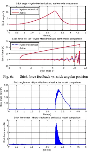
The stick force law represents the stick force as a function of the stick position. The breakout point is the force level required to start a stick movement. The force is then proportional with the stick position. When the stick is dropped at an approximately stick angle of 11 degrees (time = 3s), it comes back and stops to its initial position.
Simulations results (Fig. 6.a) show that during the first part of the simulation (“hands on” configuration, the stick position is imposed by the pilot), the active system perfectly matches the hydro-mechanical system. The stick force is therefore accurately reconstructed from the Internal Model Reference. After three seconds of simulation, time from which the stick starts returning to its initial position, the stick is less damped in the active case than in the hydro-mechanical case. But in this unusual case, the pilots do not handle the stick and the stick
Tks_coupMES Tkr_coup Ωd_coup E vl_axis Fk_rod Fk_rod vl_rod vpiston vl_axis Fl_axis
Internal Reference Model structure IRM block Ωd_coup Tkt_coup Ωd_coup Tt_coup Damper MS Ωdamper Tdamper
Spring based element
MS Tblocked Ωblocked Fl_axisMES Hydraulic booster Q xdist Qch Pch CHMPpiston Qpiston FQ_piston vpiston Fpiston vpiston vl_bp Fbp kin To preserve kinematic ratio Reference 1 « Angular Speed » Reference 2 « Linear speed » Fl_axisMES Tkt_coup Ωt_coup Ωt_coupREG 1/B ΩactiveREF ΩactiveMES 1/ EMC TactiveREG iactiveREF vcmdREG MODEL CONTROL Voltage source B EMC ES Active element Motor inertia Motor inductance Tt_active Ωactive Ωactive Tactive iactive vcmd vemf iactive iactiveMES
Speed loop Current loop
Damper
Spring based element coupling Stick stiffness
K_stick
Lower rod stiffness K_lRod Pilot Ωd_coup Tks_coup Vs_rod Fk_stick Vpilot MS A E Tkr_coup Ωd_coup vl_axis Fk_rod Fk_rod vl_rod Fk_stick Damper inertia J_damper D Ωd_coup Tt_coup EMC Ωdamper Tdamper MS edamper idamper Tt_damper Ωdamper vleq_axis Lower rod eq. inertia M_leqRod Fleq_axis Damper Stick Tuning path Measured signal Load
Eq. Load mass M_eqload vload Fload EMC MS ES Ωscrew Tstab Electro-mech. conversion Tu_axis Ωscrew Power voltage control Stabilisation act. inertia J_stab istab estab vload Fu_axis
Upper rod & endless screw stiffness K_uRod Upper Rod coupling Stabilisation act. Inductance I_stab Ustab istab Stabilisation actuator kr s Fu_axis vstab Irreversible screw/gear vl_axis Fl_axis vu_axis Fu_axis Bond 1 Bond 2
force feedback signal is not of interest. However, it remains important that the stick position fit with the one of the hydro-mechanical system, which is the case: there is no over-shoot on the stick position and the stick angle error remains insignificant (less than 0.08°, see Fig. 6.b).
0 0.5 1 1.5 2 2.5 3 3.5 4 4.5 5 -5 0 5 10 15
Stick angle - Hydro-Mechanical and active model comparison
Time (s) S ti c k a n g le ( °) Hydro-mechanical Active -2 0 2 4 6 8 10 12 -10 0 10 20 30
Stick force feel law - Hydro-Mechanical and active model comparison
Stick angle (°) S ti c k Fo rc e ( N ) Hydro-mechanical Active
Fig. 6a Stick force feedback vs. stick angular potision
0 0.5 1 1.5 2 2.5 3 3.5 4 4.5 5 0 0.02 0.04 0.06 0.08
Stick angle error - Hydro-Mechanical and active model comparison
Time (s) S ti c k a n g le e rr o r (° ) 0 0.5 1 1.5 2 2.5 3 3.5 4 4.5 5 0 1 2 3 4
Stick force error - Hydro-Mechanical and active model comparison
Time (s) S ti c k f o rc e e rr o r (N )
Fig. 6b Stick angle and stick force feedback error V. CONCLUSION
The model of a helicopter flight axis control is represented using the Energetic Macroscopic Representation. The model is mainly composed of hydro-mechanical elements. An evolution of the system is proposed in order to simplify the helicopter flight control architecture with active technology. The solution leads to a reduction of the number of hydro-mechanical elements, which are generally heavy and without evolution possibility, while preserving the global flight axis control behaviour.
A methodology is proposed to help the designers transforming the hydro-mechanical system into a new active system. The methodology is based on the Internal Model Reference (IRM) principle. The general idea is to simulate the behaviour of the hydro-mechanical system through the control architecture of the active element. The computed reference is then used as a speed set-point to drive the motor of the active element. The EMR energetic method has been used to define a systematic model based control architecture respecting natural
causality. The speed and current controllers deduced from the inversion have been designed using the Naslin polynomial methodology. Both hydro-mechanical and active systems have been simulated using Matlab/Simulink software. Simulation results show that the IRM contained in the new active helicopter flight axis control contributes to the conservation of the hydro-mechanical system behaviour. The stick force feedback is preserved, validating the proposed methodology.
Future works are oriented on the simplification of the IRM. The more elements are removed (from the process to be simplified), the higher the order of the IRM is. The order of the IRM shall be decreased to reduce the complexity of the control and the computation time. The methodology would be based on the comparison of energy activity of each energy storage element included in the IRM.
ACKNOWLEDGMENT
This work has been supported by Olivier Honnorat, innovation project manager at Eurocopter, Marignane (Fr).
REFERENCES
[1] Hautier, J.P. Barre, P.J., “The causal ordering graph - A tool for system modelling and control”, 2005.
[2] Martin M., Gomand J., Malburet F., Barre P.J., “Methodology for Modelling and Control of a Complex Multi-physic System – Case of helicopter flight axis control”. EMS2012, unpublished. [3] Fitzsimons, P.M., Palazzolo J.J., “Part I: Modeling of a
one-degree-of-freedom active hydraulic mount”, Journal of Dynamic Systems, Measurement, and Control, 1996.
[4] H. M. Paytner, “Analysis and Design of Engineering systems”, MIT-Press, Camb, MA, 1961.
[5] D. C. Karnopp, D. L. Margolis, R. C. Rosemberg, “System Dynamics - Modeling and Simulation of Mechatronic Systems”, Wiley Interscience, ISBN 0-471-33301-8, 3rd iss. 2000.
[6] P. J. Barre, A. Bouscayrol, P. Delarue, E. Dumetz, F. Giraud, J. P. Hautier, X. Kestelyn, B. Lemaire-Semail, E. Semail, “Inversion-Based Control of Electromechanical Systems Using Causal Graphical Descriptions”, IEEEIECON’ 06, Paris, Nov. 2006.
[7] Chikhaoui Z., Gomand J., Malburet F., Barre P.J., Complementary use of BG and EMR formalisms for multiphysics systems analysis and control, Proceedings of the 11th biennal
conference on Engineering Systems Design and Analysis, ESDA 2012.
[8] Morari M., Zafiriou E., “Robust Process Control”, 1989
[9] Martin M., Gomand J., Malburet F., Barre P.J., “Modelling and control of an effort feedback actuator in helicopter flight control using Energetic Macroscopic Representation”, IMAACA 2011 [10] Karnopp, D., “Computer Simulation of Stick-Slip Friction in
Mechanical Dynamic Systems”. ASME Journal of Dynamic Systems, Measurement and Control, Vol. 107, 100-103, (1985). [11] Harris, C.M., “Exploring smoothness and discontinuities in
human motor behavior with Fourier analysis”, Mathematical biosciences, vol. 188, pp. 99-116. 2004.