Publisher’s version / Version de l'éditeur:
Soil Science, 84, 4, pp. 291-299, 1958-01-01
READ THESE TERMS AND CONDITIONS CAREFULLY BEFORE USING THIS WEBSITE.
https://nrc-publications.canada.ca/eng/copyright
Vous avez des questions? Nous pouvons vous aider. Pour communiquer directement avec un auteur, consultez la
première page de la revue dans laquelle son article a été publié afin de trouver ses coordonnées. Si vous n’arrivez pas à les repérer, communiquez avec nous à PublicationsArchive-ArchivesPublications@nrc-cnrc.gc.ca.
Questions? Contact the NRC Publications Archive team at
PublicationsArchive-ArchivesPublications@nrc-cnrc.gc.ca. If you wish to email the authors directly, please see the first page of the publication for their contact information.
NRC Publications Archive
Archives des publications du CNRC
This publication could be one of several versions: author’s original, accepted manuscript or the publisher’s version. / La version de cette publication peut être l’une des suivantes : la version prépublication de l’auteur, la version acceptée du manuscrit ou la version de l’éditeur.
Access and use of this website and the material on it are subject to the Terms and Conditions set forth at
The mechanism by which water moves through a porous material
subjected to a temperature gradient. I. Introduction of a vapor gap into
a saturated system
Kuzmak, J. M.; Sereda, P. J.
https://publications-cnrc.canada.ca/fra/droits
L’accès à ce site Web et l’utilisation de son contenu sont assujettis aux conditions présentées dans le site LISEZ CES CONDITIONS ATTENTIVEMENT AVANT D’UTILISER CE SITE WEB.
NRC Publications Record / Notice d'Archives des publications de CNRC:
https://nrc-publications.canada.ca/eng/view/object/?id=2e97a730-4ddb-4b6c-beca-a8e8ad55f992 https://publications-cnrc.canada.ca/fra/voir/objet/?id=2e97a730-4ddb-4b6c-beca-a8e8ad55f992Ser
TH1
N2lr2
no.
47
c. 2
NATIONAL
RESEARCH
COUNCIL
CANADA
THE MECHANISM BY WHICH WATER MOVES THROUGH A POROUS
MATERIAL SUBJECTED TO A TEMPERATURE GRADIENT: I.
INTRODUCTION OF A VAPOR GAP INTO A SATURATED SYSTEM
J. M. KUZMAK AND P. J. SEREDA
NRC 4491
REPRINTED FROM SOIL SCIENCE
VOL. 84, NO. 4. OCTOBER 1957. P.291.299
RESEARCH PAPER N O . 4 7
O F THE
DIVISION O F BUILDING RESEARCH
OTTAWA JANUARY 1958
This p u b l i c a t i o n
i s
b e i n g d i s t r i b u t e d by t h e D i v i s i o n o f B u i l d i n g Research of t h e N a t i o n a l Research Council a s a c o n t r i b u t i o n towards b e t t e r b u i l d i n g i n Canada. I t should n o t be reproduced i n whole o r i n p a r t , w i t h o u t p e d s s i o n of t h e o r i - g i n a l p u b l i s h e r . The D i v i s i o n would be g l a d t o be, of a s s i s t a n c e i n o b t a i n i n p such permission,P u b l i c a t i o n s of t h e D i v i s i o n of B u l l d i n g Research may be o b t a i n e d by m a i l i n g .the a p p r o p r i a t e r e m i t t a n c e , ( a Bank, Eyress, o r P o s t O f f i c e Money Order o r a cheque nade payable a t p a r i n Ot.tawa., t o t h e R e c e i v e r General of Canada, c r e d i t N a t i o n a l R e s e a r c h c o u n c i l ) t o
the
M a t i o ~ a l Research C o m c i l ,Ottawa, Stamps a r e not 2ccaptnbl-e,
A coupon slvstem has been i n t r o d u c e d t o make payments f o r publl-cat io n s r e l a t i v e l y s i m p l e ,
Coupons a r e a v a i l a b l e i n denominations of
5,
25, and c e n t s , and may be o b t a i n e d by making a r e - m i t t a n c e a s i n d i c a t e d above, These coupons m y be used f o r t h e purchase of a l l N a t i o n a l Research C o u n c i l p u b l i c a t i o n s i n c l u d i n g s p e c i f i c a t i o n s of t h e Canadian Government S p e c i f i c a t i o n s Board.Reprinted from SOIL SCIENCE Vol. 84, No. 4, October, 1857
Printed in U.S.A.
A N A L Y Z E D
T H E MECHANISM BY WHICH WATER MOVES THROUGH A POROUS MATERIAL SUBJECTED T O A TEMPERATURE GRADIENT: I.
INTRODUCTION OF A VAPOR GAP INTO A SATURATED SYSTEM
National Research Council, Canada'
Received for publicntion January 2, 1057
Although the movement, due t o a temperature gradient, of moisture through porous materials has been studied by many workers, the mechanism by which moisture moves through such materials remains a point of controversy (1, 5, 11, 13, 14). There are two theories which lead t o two generally accepted and possible mechanisms. The first theory postulates that the moisture moves from hot to cold regions in the vapor phase and that the driving potential is the vapor pressure difference which corresponds to the temperature difference. Strong evidence in favor of this mechanism is the absence of moisture move- ment due to a temperature gradient in a fully saturated system where there is no vapor phase (6). The second theory postulates that some of the water moves in the liquid phase in the form of a film. This concept was put forward to account for the fact that the experimentally observed rate of movement is about ten times as large as the calculated rate based on vapor diffusion (1, 14).
Some experiments to study the mechanism of moisture movement due to a temperature gradient through porous materials have been carried out in this laboratory. This paper deals with the influence of a gap (of vapor) on the rate of movement in an otherwise saturated system.
APPARATUS AND PROCEDURE
The theoretical relationships involved and the practical aspects of the con- struction of the apparatus have been described by others (4, 9). The main prin- ciple involved is that, under isothermal conditions, the moisture content of a porous material in contact with a saturated porous plate is determined by the difference in pressure across the plate. The moisture content decreases as the difference in pressure increases. This difference in pressure is also frequently referred to as the suction (4, 10). The maximum pressure difference that can be used is less than the pressure required to empty the pores of the plate. This pressure is given by the equation:
where
P is the pressure ( d ~ n e s / c m . ~ ) y is the surface tension (dynes/cm.)
m is the hydraulic radius (ratio of area of pore to perimeter of pore) (cm.) (2) This paper is a contribution from the Division of Building Research, National Research Council, Canada, and is published with the approval of the Director.
I n equation (1) the coiltact aiigle between the water and the porous plate is assumed to be zero. The contact angle between water and the clean surfaces of a material such as that constituting the porous plate used in the present ex- periment has been shown to be zero or very small (8). Also, the relative humidity, in excess of 99.9 per cent, maintained within the apparatus favors a contact angle of zero.
The apparatus used in the present iilvestigation was u modificatioil of that developed by Srvenson and Sereda (12) to maintain a fixed moisture content in a sample a t the same time that the movement of moisture due to a temperature gradient is taking place. Since work in which the apparatus was used t o regulate the moisture content of a sample will be reported in a subsequent paper (7),
the functioning of the apparatus with as well as \vithout a sample will be de- scribed a t this time.
i
\V \TIC12 AIOVEMISST TIIlEOUCilI POlLOUS A1 \TEILI.\L 2'3:; The appar:lt,us is show11 ill half section in figiue 1 . A cylindrical saniplc il
\\,as confined 1)y two ideiitic~al c:eramic p o ~ ~ u s platcs B which were sealecl iuto
cylind~,ical lucitc sectiolis (7 1)y rubber "0" rings 1') a i d fibre rings
h'.
The otherside of the porous plates was kept in colitact with water a t atmosphel-ic pressure. The grooved reservoir holdilig this water \\;as corlnected to h o r i z o ~ ~ t a l measurillg pipettes 1)y glass tubing If'. The space surrou~idirig t,he s:~inplc was colifii~ecl by
a luoitc rilig B and r~i1)l)er seals H . This arrangement perrnit'ted the two porous
plat,es to come into aligllment with the two faces of the sanlple and to remain so throughout the experiment. T o prevent colidensation on the rillg G, heated water from a constant temperature bath was c~irculatccl t'hrough the circum- ferential groove I. This groove \\.as confilled by a tightly fitting lucitc ring J .
Air a t :uny give11 pressure, colitrollecl by a pressure ~,cgulator, was introduceel iilt'o the spacc around the sample through a tube K. The pressure \\.as read fro111 a mercury manometer. Pressures larger t,han those \vhich coulcl be read on t,hc manometer \\;ere reacl on the gauge of the pressure regulator. Silice the pressurc
011 the ot,her side of the porous plate 1 ~ : ~ s atmospheric, t'hc nlaliometer pressurc
gave the pressure cliffcrcnce or suct'ioli to which the sample was sul~jccted. By \.al*ying this pressure, the moistul,c colitent of the sample 1 ~ : ~ s \,ariecl.
The cylindrical spaces 0 \rere (.onfined by t,he lucite plugs L \vhich were re-
tained by b l ~ s rings iJI aild sealed by rul.)l)er rings AT. T o produce a temper:~t'urc clift'erciicc across the sample, the spaces 0 \\;ere colillec:ted by tubing P to sources
of \v:~t,er colitrolled a t two clifl'eelcilt colistalit t'emperatures. During the mo\rc- illcrit of moist'ure due t o this temperature diBerence, the porous plat>(; a t the higher t,emperature acted :IS a s o ~ u c ~ c of wat,er \vhile the other acted as a sink.
The out,er lucite cylilidcrs R permitted parts C and their assembly t o fiuiction a s pistons. The sc:~ls S nllo\\:ed the parts to slide frccly. 1Cil.m contact of the
polbous plates against the faces of the sample ~ v a s achieved by air pressure in the spaces Q larger than that i l l the space surrounding t,he sanlple. The dif-
fcrenre ill prcssurc bet\vecll these two spac:es \\;as kept colistalit a t 1.35 rm. of water ill orclcr to maintain a colistailt contact pressurc het\veen s:~mplc and porous platcs. The air was z~dnlitted illto the space Q through metal tubing t T .
r 7
1 o lileasure tcml)er:~tures inside the apparatus, copper-const,ant;ali thermo- couples 7' were brought out thl,ough snlall holes in the I~ocly of part C. The holes were scaled up with wax. The elitire asscrn1)ly ~ v a s held together by six tie 1)olts TT.
I n the presciit esperinlclit, the apparatus was usccl ~vithout a si~nlplc bct,~vcell t,hc porous plat,es. The faces of the t\\,o porous plates were I~rought ill cont,act with one another. B e ~ a ~ s e the faces ~vcrc planar, thcrc mere numerous points of contact. This proclnced a definite pore systenl at; t'he interface. I t \\;as the effect of t,he gap composed of these pores as ~vcll as the elrect of the gap b e t ~ ~ ~ e c i i the scpari~tccl plates that ~ v a s st,udicd.
The gap was varied as follo\vs. The porc syst,clll a t the i ~ ~ t o r f a c c ~ v i ~ s ~ ~ a r i c c l 1)y altering the t,esture of t,he surface of the faces 1)y grillding them wilh car- boruntlum polvder, Ko. 80 to produce a coarse su1.fac.e and KO. 600 t , ~ produce n fine surface. X rotating autorllat,ic polishing mnc*hille \\-as used to ellsure that,
204 I<UZ%IAIC A N D SEREDA
Frc;. 2. X21. SL;nl..~cn 017 I'onors PLITE GROCSI) wITII C A R B ~ R C S I I G A I l ' o w n ~ n
iYo. SO (lejl) . \ A D No. 600 (righl)
thc faces \\-ere planar. The texture of these surfaces is s h o ~ ~ r n in figurc 2 , left, and right, respectively. Nest, the fine surfarcs were separated by four shims, eclually spaced around the perimeter, b e t ~ ~ e e n the two porous platcs. Shinls 0.0025 and 0.110 cm. thick were uscd; each shim nTas 0.4 cm. square.
X teinperature gradient across the t ~ v o porous platcs \\-as iml~oscd, us described, by circulatiilg water a t O.G°C. through one side of the apparatus and water a t 49.0°C. through the other. When the 0.110 cm. shims \\-ere uscd, ail attempt
as inade to get a rough iclea of the telnperature of the surfaces across the gap by placing S o . 30 B and S gauge copper-constai1tai1 thermocouples on these surfaces. It was realized t h a t the temperatures obtained in this manner \vould likcly be in crror since the sizc of the actual junction of the thermocouplc wires is relatively large \\,hen compared with the distailce bct~vecn the platcs. lcor thc thinner shims and for the experiments with no shims, no attcinpt \\-as illaclc t o obtain this temperature. I-Io\\-ever, t o ascertain ~vhcthcr thc temperature across the plates ~raricd during an expcriment, thermocouples \\-crc placed in coiltact I\-ith the outside surfaces of the plates.
The quantity of water in the gap was variccl by varying the air pi-essure in the chambm supplied through tube K. Coiltact het~vecn the plates was int~in- tailled by ail opposiilg pressure a s described.
T h c ratc of flow of the water was obtained by ohser\riiig the rate of mo~rcii~cnt of the inciiisri in the two horizontal pipettes. TIVO pipette..; \\-ere used, one to iilclicate thc flow into the system, the other to indirate the flow out. A steacly- state coildition \\-as indicated when these rates were equal.
The ratc of flow through the porous platcs due t o a hydraulic head \\-as incasurecl.
The porous platcs \\-ere 7.6 cm. in diameter and about 0.76 cm. in thickncl~bh. The pressure required t o einpty the pores was csperimcntally determined as ,5000 cm. of water.
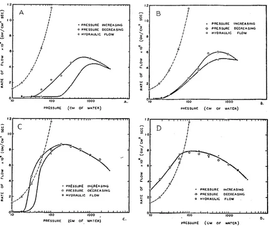
F'or thc four gaps usccl, figure :J she\\-s thr rtllationship bet\\-ccil t h c r ~ ~ t c of flow due t o the temperilture gradient, and the prcssure used to unsilturate the gap. Each curve is t,hc :Lrrerage of three ruils which ~ ~ r c r c in good agreement. il
WATER MOVEMENT THROUGH POROUS MATERIAL 295 I 2
2
R 1 0 5 '.z
8 .-
PRESSURE (CM OF WATER) PRCSSURC ( C U OF W ~ T E R )
, , . ,
.
,.
. .
. . .
, . , . . . . , . . . . .r A , I - I t PRESSURE INCREASING I # O P R E S S U E DECREASING , 0 HYDRAULIC FLOW , 1 2 7 " 1 0 I '.z e
-
2 r 6 3 S LL LL 4g
1 2 - , , ,.
, ,,,. , , , , , ,,,..
, , , , ,,, Pc
I 1 0 - I I '-\"\
' - a PRESSURE INCREAslNo o PRESSURE O<CREASING 0 HYDRAULIC FLOW LL 1 0 0 0 , r" B I I I I.
PRESSURE INCREASING I I 0 P R E S S U E DECREASING I 0 HYDRAULIC FLOW I I d I I I,/"
61
2 , . , , ' ://
0. 1 2 - , , 1 1 ,,,,, 1 1 1 , 1 , , * , , , , , , l,,. PD
I * 1 0 - I I 1 I U I PRESSURE INCREASING 0 PRESSURE OECREASING 0 WYORAULIC FLOW 100 I 0 0 0 8.PRESSURE (CU O F WATER) C.
FIG. 3. FLOW DUE TO THE TEMPERATURE GRADIENT W H E N FINE-TEXTURED (top lejt) OR
COARSE-TEXTURED ( t o p right) SURFACES A R E I N CONTACT US. THE PRESSURE USED T O U N - SATURATE THE PORE SYSTEM AT THE INTERFACE; AND W H E N FINE-TEXTURED SURFACES
A R E SEPARATED B Y 0.0025 cm. (lower lejt) OR 0.119 cm. (lower right) SHIMS U S . THE PRESSURE
USED TO UNSATURATE THIS G A P
curve showing the relationship between the rate of flow through the porous plates and hydraulic head is also shown in these figures.
In each figure, as the pressure increases, the rate of flow increases, passes through a maximum, and then decreases. The maximum flow is smallest for the gap between the fine surfaces in direct contact, larger for the gap between the coarse surfaces, and largest for the gap between the fine surfaces separated by the 0.0025 cm. shims. The maximum for the gap formed by the 0.119 cm. shims is smaller than that for the 0.0025-cm. gap. The pressure a t which the maximum occurs is highest in A, figure 3, and decreases from A through D (fig. 3). A,
B, and C in figure 3 exhibit a hysteresis.
Since the width of the gap formed by the shims was known, the pressure re- quired to empty the gap could be calculated. The equation used was:
296 KUZMAK AND SEREDA where
r is the radius of curvature of meniscus (em.)
y is the surface tension (dynes/cm.)
P is the pressure (dyne~/cm.~)
The distance between the plates is 2 r . Table 1 shows the relationship between the pressure and the space between parallel plates that the pressure will empty. From this table, it may be noted that the gap produced by the 0.0025 cm. shims will not empty until a pressure of about 56 cm. of water is applied. Likewise, the lowest pressure used, a pressure of 10 cm. of water, is more than enough to empty the gap produced by the 0.119-cm. shims.
Consider D, figure 3. If there were no temperature gradient across the 0.119- cm. gap, i t would empty when a pressure of 10 cm. of water was applied. If now the temperature gradient is applied, vapor distills across the gap and condenses on the surface of the cold plate. Once the vapor has condensed on the cold plate, the pressure of 10 cm. of water, acting as a hydraulic head, causes the liquid to flow through the plate. Two rates are therefore involved: the rate of distillation across the gap and the rate of liquid flow through the plate due t o the pressure acting as a hydraulic head.
The curve showing the rate of flow through the porous plate due to a hydraulic head equal to the air pressures used is shown in the figure. The rate of flow a t a pressure of 10 cm. of water is seen t o be 1.2 X 10-Q./cm.2sec. By extrapola- tion, the rate of distillation across the gap a t this pressure is about 8 X
g./~m.~sec. Because of the difference in the two rates, water must have accumu- lated on the surface of the cold plate. This accumulation would continue until the gap filled to the point where the water probably bridged the gap over a certain area. This reduced the area of the vapor phase and hence reduced the total flow of vapor to the point where the two rates were equal. Experimentally, the two rates were always equal at the steady state, and it is this rate which is plotted in figure 3. At this pressure, therefore, the observed rate is governed by the rate of flow of liquid through the porous plate.
As the pressure is increased up to a pressure of about 70 cm. of water, the observed rate of flow increases, corresponding to the increase in the rate of flow through the porous plates. In the meantime, the rate of distillation decreases in agreement with the known fact that the rate of distillation varies inversely as
TABLE 1
Relationship between pressure a n d the space between parallel plates that the pressure will e m p t y
Pressure
I
Distance Between Platescnt. o j waler 10.0 17.8 3 1 . 6 56.2 100.0
WATER MOVEMENT THROUGH POROUS MATERIAL 297 the pressure in the space above the liquid. At a pressure of about 70 cm. of water, the two rates of flow are equal. Therefore a t this pressure the gap becomes empty.
As the pressure increases beyond this value, the gap remains empty and the observed rate of flow decreases, corresponding t o the decrease in the rate of distillation, which is now the rate-controlling process. The variation in the observed rate of flow over the entire range of pressures used, therefore, is ac- counted for.
Theoretically, the portion of the curve t o the left of the maximum for the experiment with the temperature gradient across the gap should coincide with the curve showing the flow due to a hydraulic head. The reason for its failure t o do so is not known. This peculiar behavior requires further study.
According to calculation, the 0.0025-cm. gap remains saturated as the pres- sure increases t o a value of about 56 cm. of water. At this pressure the gap emp- ties. If the transfer of moisture takes place in the vapor phase, there should be no flow a t the pressures a t which the gap is saturated and maximum flow a t the pressure a t which it empties. I n general, in agreement with the prediction, C, figure 3, shows that there is virtually no flow a t pressures below 56 cm. of water and a large flow a t 56 cm. T h a t the rate of flow a t 56 cm. is not the maximum is again accounted for by the rate of flow through the porous plate being the slower, and therefore, the controlling rate, a t this pressure. The further rise and then fall in the observed rate of flow as the pressure increases is accounted for in the same way as for D, figure 3.
Because of hysteresis, the moisture content of a given porous sample a t any given suction, over a certain range, is higher when the suction is approached from zero suction than when approached from the opposite direction (3, 4). This same hysteresis in the moisture content is shown by the 0.0025-cm. gap, and is reflected by the hysteresis in the rate of flow. D, figure 3, shows no hys- teresis because the gap is too large t o show this effect in this range of pressures, I n A and B, figure 3, the rate of flow through the porous plates does not enter as a factor influencing the observed rate of flow. The observed rate of flow due to the temperature gradient is much lower a t each pressure than the flow through the porous plates. I n A (fig. 3) for the h e surfaces in contact, the space between the plates is saturated below a pressure of 200 cm. of water and the flow is therefore zero. As the pressure is increased beyond this value, the space is pro- gressively emptied and the rate of flow increases, corresponding t o the increase in the area of the vapor phase. At a pressure of 1000 cm. of water, the space is completely empty and the flow is a t a maximum. A further increase in pres- sure produces no further increases in effective area but does reduce the rate of distillation for the reason already mentioned. I n B (fig. 3) the much larger gap between the coarse surfaces begins to empty a t a pressure of 30 cm. of water. Again, the hysteresis shown in A and B (fig. 3) is due to the hysteresis in mois- ture content.
When the gap between the plates separated by the shims is emptied, no film flow is possible. On the other hand, when the pore system a t the interface of
298 KUZMAK AND SEREDA
the two plates is emptied, film flow is possible a t the points of contact. However, the curves in A and B (fig. 3) show no characteristic which would indicate appreciable film flow.
Comparing A , B, C, and D (fig. 3) the shift of the maximum toward lower pressures occurs because the pressure required to empty a gap decreases as the width of the gap increases. The height of the maximum increases as the texture of the surface becomes coarser because of the increase in area for vapor flow brought about by a reduction in the area of the bearing surface. The maximum is highest when shims are used in agreement with the fact that the area of the bearing surface is a t its smallest a t this time. That the maximum for t h e 0.119- cm. gap is less than that for the 0.0025-cm. gap is in agreement with the require- ment that, with other factors constant, the rate of distillation decreases with increasing distance between the plates.
The temperature difference across the 0.119-cm. gap was found t o be 25
-
24 = 1°C. by thermocouples placed on the plate surfaces. Hence, the rate of distillation across this gap may be calculated, using the equation:
MDP Po
-
PCw = . -
R T z P
where
W is the rate of distillation (gm./~m.~sec.)
M is the molecular weight of water (g./mole)
D is the coefficient of diffusion ( ~ m . ~ / s e c . )
R is the gas constant (ergs/"C. mole)
T is the absolute temperature of the evaporating liquid ("A.)
x is the distance between the evaporating liquid surface and the condensing surface (cm.)
P is the pressure in the space above the liquid (dyne~/cm.~)
Po is the saturation vapor pressure of the evaporating liquid (dynes/cm.2)
PC
is the saturation vapor pressure a t the condensing surface (dynes/cm?) Substituting the appropriate values in the above equation, the result for a pressure of 100 cm. of water is:= 2.43 X lop6 g./cm.2 sec.
This value is about one-third of the experimental value of 8 X g./~m.~sec. a t this pressure. This is probably good agreement in view of the uncertainty with which the temperature difference was known. The actual temperature difference was likely larger, in which case the agreement between the calculated and experimental rate would improve.
CONCLUSION
I n this system of two porous plates and the gap between them, there was no flow due t o the temperature gradient a s long as the gap remained saturated.
WATER MOVEMENT THROUGH POROUS MATERIAL 299 Flow began when the gap began t o unsaturate. The flow attained its maximum when the gap was completely unsaturated. These results are in agreement with the theory that moisture movement due to a temperature gradient across a porous material takes place in the vapor phase.
REFERENCES
(I) B o u ~ o u c o s , G. J. 1915 Effect of temperature on the movement of water vapor and capillary moisture in soils. J. Agr. Research 5 : 141-172.
(2) CARMAN, P. C. 1941 Capillary rise and capillary movement of moisture in fine sands. Soil Sci. 52: 1-14.
(3) CARMAN, P . C. 1953 Properties of capillary-held liquids. J. Phys. Chem. 57: 56-64. (4) CRONEY, D . 1952 The movement and distribution of water in soils. Geotechnique 3 :
1-16.
(5) GURR, C. G., MARSHALL, T . J., A N D HUTTON, J. T . 1952 Movement of water in soil
due t o a temperature gradient. Soil Sci. 74: 335-345.
(6) HUTCHINSON, H . P., DIXON, I. S., AND DENBIGH, I<. G. 1948 The thermo-osmosis of
liquids through porous materials. Discussions Paraday Soc. No. 3, pp. 86-94. (7) KUZMAK, J. M., A N D SEREDA, P. J. The mechanism by which water moves through a
porous material subjected t o a temperature gradient: 2. Soil Sci. In press. (8) LINFORD, L. B. 1930 Soil moisture phenomena in a saturated atmosphere. Soil Sci.
29 : 227-237.
(9) RICHARDS, L. A., AND FIREMAN, M. 1943 Pressure-plate apparatus for measuring
moisture sorption and transmission by soils. Soil Sci. 56: 3 9 5 4 0 4 .
(10) RICHARDS, L. A. 1949 Methods of measuring soil moisture tension. Soil Sci. 68: 95-112.
(11) SMITH, W. 0. 1943 Thermal transfer of moisture in soils. Trans. Am. Geophys. Union 2 : 511-524.
(12) SWENSON, E. G., AND SEREDA, P. J. 1955 Preliminary experiments on the movement
of water through concrete and other materials due t o a temperature gradient.
Bull. No. 1 , Division of Building Research, National Research Council (Canada)
No. 3668, pp. 102-109.
(13) TAYLOR, S. A., A N D CAVAZZA, L. 1954 The movement of soil moisture in response t o
temperature gradients. Soil Sci. Soc. Amer. Proc. 18: 351-358.
(14) WINTERKORN, H. F. 1947 Fundamental similarities between electro-osmotic and thermo-osmotic phenomena. Highway Research Board, Proc. 27: 443454.