Publisher’s version / Version de l'éditeur:
Vous avez des questions? Nous pouvons vous aider. Pour communiquer directement avec un auteur, consultez la
première page de la revue dans laquelle son article a été publié afin de trouver ses coordonnées. Si vous n’arrivez pas à les repérer, communiquez avec nous à [email protected].
Questions? Contact the NRC Publications Archive team at
[email protected]. If you wish to email the authors directly, please see the first page of the publication for their contact information.
https://publications-cnrc.canada.ca/fra/droits
L’accès à ce site Web et l’utilisation de son contenu sont assujettis aux conditions présentées dans le site LISEZ CES CONDITIONS ATTENTIVEMENT AVANT D’UTILISER CE SITE WEB.
Internal Report (National Research Council of Canada. Division of Building Research), 1958-02-01
READ THESE TERMS AND CONDITIONS CAREFULLY BEFORE USING THIS WEBSITE. https://nrc-publications.canada.ca/eng/copyright
NRC Publications Archive Record / Notice des Archives des publications du CNRC :
https://nrc-publications.canada.ca/eng/view/object/?id=de425598-d870-463d-925e-02eeb4ba6363 https://publications-cnrc.canada.ca/fra/voir/objet/?id=de425598-d870-463d-925e-02eeb4ba6363
Archives des publications du CNRC
For the publisher’s version, please access the DOI link below./ Pour consulter la version de l’éditeur, utilisez le lien DOI ci-dessous.
https://doi.org/10.4224/20386616
Access and use of this website and the material on it are subject to the Terms and Conditions set forth at Loading tests on Douglas fir and Eastern spruce trusses
LOADING TESTS ON DOUGLAS FIR AND
EASTERN SPRUCE TRUSSES
by
A.T.
Hansen(A co-operative project with the Forest Products Laboratories, Department of Northern. Affairs
and National Resources, Ottawa)
Report ャセッN 138
of the
Division of bオゥQ、ゥセc Research
otセイャエゥva
The structural performance of roof components is being studied by the Division as part of a reassessment of the structural design of houses. Previous reports have dealt with a structural test of a full-scale house, the structural performance in the laboratory of a w-truss design, and a comparison of trusses and conventional rafter constructions. This work has led to a re-appraisal of the loading require-ments for house roof systems and to a program of field
measurements on the actual snow loads occurring on roofs. Laboratory studies are being carried out to determine the performance of various roof constructions of both con-ventional and trussed designs, under short time and
relatively long-term loading. The results of investigations of a type of lightweight nailed W truss are noV'! being presented. Tests carried out to determine the effects of intermediate
support such as might be provided by interior partitions are described in Part II of this report.
In all its work in which wood is involved as a material, the Division has the pleasure and ーャセカゥャ・ァ・ of working closely with the Forest Products Laboratory of the Department of Northem Affairs and National Resources of which Colonel
J.
H.
Jenkins is Chief. Although the Division of Building Research accepts full responsibility for the work herein described, it was carried out in closeconsul-tation with the Forest Products Laboratory, and it is for this reason that this liaison is indicated on the title page.
Ottawa
by
A.T. Hansen
Part I: Short-Term and Long-Term Loading Tests on Douglas
Fir and East ern Spruce Trusses Vii thout Intermediate
Supports
In DBR Internal Reports 81 and 113, the results of
investigations of the strengths of various types of con-ventional and trussed roof constructions are presented. This preliminary work on the strength of roof frames formed the basis for, and led to the development of lightweight
nailed
"VI"
truss designs for various spans and roof slopes.The results of the test work on these are recorded in DBR
Internal Report 119.
All of the test work up to this time has been on
structures made of eastern spruce lumber. As the next stage
in the development of light107eight roof trusses , it was decided to design and load test trusses made from Douglas
fir. In DBR Report 119, the trusses were designed principally
for Eastern Canada and the relatively high cost of plywood
influenced the design of the truss. As the trusses made
from Douglas fir are intended principally for use in the
West where ーャセカッッ、 is not as expensive, a greater amount of
plywood was used in this design, and several desirable
features have been introduced, therefore, in the manufacture of the trusses.
The truss design, although developed primarily for western materials, was tested using eastern spruce as well as Douglas fir since it was thought that, although the truss might be more expensive to build in Eastern Canada, some of the desirable features might make it preferable from a
manufacturing point of view to the designs i..nDER Report 119.
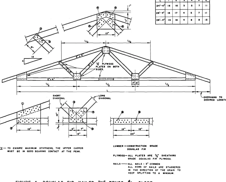
Description of Trusses
The trusses were designed for spans of 24, 26 and 28
ft and with 4/12 and 5/12 roof slopes. The designs are shown
iYJ Fie-s. 1 to 4.
Previous tes-t vmrk (DBB Report 119) showed tllat the
stiffness and strength of trusses decreased with lower
slopes and longer spans. Therefore, rather than test the full
イ。ョサセ・ of roof' slopes and spans as was done in DBR Report 119,
tests were conducted on 26- and 28-ft spans and 4/12 slope
if applied to steeper slopes and shorter spans.
Only 2" x 4" structural members were used in tests on Douglas fir trusses and. in all but three tests on eastern
spruce trusses. In these last three tests, 2" x 6" top and
bottom chords were substituted for the 2" x 4" members to determine the effect on stiffness.
Construction grade Douglas fir and lTo. 1 eastern
spruce lumber were used for the structural members, and セMゥョN
sheathiIlg-grade Douglas fir plyvJOod was used for the connecting plates.
The nailing Vias designed for a 30 psf snow load,
a 5 psf dead roof load and a 10 psf ceiling load with the
trusses spaced at 2 ft o.c., as with the truss designs
reported in DBR Report 119. The nail values were those
suggested by the National BUilding Code of Canada (1953). The gusset plate sizes were determined on the basis
of experience with nailed joints in previous tests. Although
further reductions in the areas of these plates are possible in many cases, it is thought that the sizes given are reason-able and no further significant reductions could be made
without adversely affecting the strength of the structure. For the sake of simplicity, gusset plate sizes were kept constant for all spans and mopes and for both the Douglas fir and spruce trusses.
Instrumentation
The instrumentation for all the tests reported in Part I was the same as that described in DBR Report 119.
Ty;p::s of Tests
For each span of truss tested, both short-term and
long-term tests, were conducted. For all tests the trusses
were loaded in pairs and sheathed with セMゥョN plywood.
Description of Short-Term Tests
To obtain average values, three tests were conducted on the 26- and 28-ft spans both for the Douglas fir and
eastern spruce trusses. This involved a total of six tests
Hセャ・ャカ・ trusses) on Douglas fir trusses and six tests on spruce trusses.
In addition to these tests three additional loading
tests were conducted on the 28-ft span spruce trusses. In
in another test 2" x 6" lower chords were used in place of 2" x 4"s; while in the third test both top and bottom chords were 2" x 6" s.
The testing procedure and loading equipment for all trusses were the same as those described for the short-term tests in DBR Report 119.
Description of LOng-Term Tests
To determine the long-term deflection characteristics of these trusses one long-term test was conducted on the
26-ft and 28-ft span for both the Douglas fir and spruce trusses.
A simulated snow load of 40 psf and a dead roof load of
5
psf was applied to the top chords by means of concrete blocks, and a 10 psf ceiling load applied to the lower chords by means of lead-filled bags in the same manner as described in DBR Report 119 (see Fig.33).
The loads were allowed to remain for a period of one month during whioh deflection イ・。、セョァウ were recorded at
increasing time intervals. At the end of this time the loads were removed and residual deflections of the trusses noted at increasing time intervals for another month.
Recording of Results for Short-Term Tests
All dial gauge readings were recorded to the nearest .001 in. and the deflection measurements to the nearest .01 in.
A summary of the observations made during the short-term tests are shown in Tables
I
andII.
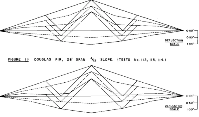
The over-all deflections of the trusses at 0, 40 and 80 psf snow loads are shown graphically in Figs. 10 to 16 and in most oases represent the average deflection charac-teristics of six trusses (three tests).
The mid span deflections of the lower ohords arc shown for the various applied loads for each test in Figs. 5 to 9. The cuiセ・ウ do not show the residual deflections of the trusses after the removal of the 40 psf snow loads during the first phase of the loading as the inclusion of these
deflections would complicate the curves. The residual de-fleotions are recorded, however, in terms of per cent recovery in Tables
I
andII.
The per cent recovery was calculated on the 40 psf snow load removal only, as in DBR Report 119. TableII
is a condensation of TableI.
The results in TableI are the average values of the performance of the two trusses in each test.
RecordlZH2 of Results for the L01lF.c.CQ.enn Tests
The results of these tests are recorded in Table III.
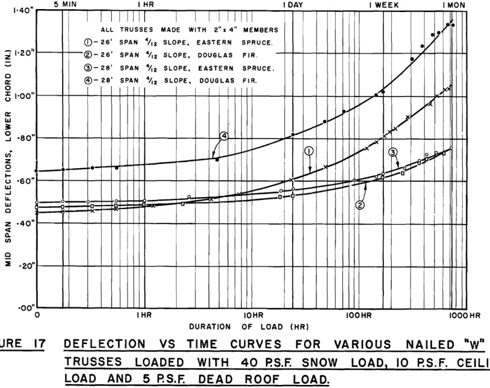
The deflection of the mid span of the Lovrer chord is plotted
against time in Fig. 17. DISCUSSION OF RESULTS
Failure Loads for Eastern sーイセ」・ Trusses
The average failure snow load for trusses with 2" x 4"
top and bottom chords was 135 psf for the 28-ft span エセjウウ・ウ
and 127 psf for the 26-ft span trusses, although one would
ョoャセ。ャャケ expect the longer span to collapse at the lower
snow load.
It may be of interest to note, however, that the same trend in breaking loads was apparent in the results described in DBR Report 119 in which the average failure loads were 130 and 131 psf for the 26-ft and 28-ft spans respectively (4/12 slope).
In test No. 115, when 2" x 6" top chords were used,
the failure load was 171 psf. In test No. 116 when. 2" x 6"
bottom chords were used the failure load was 140 psf. In
test No. 117 when both 2" x 611 top and bottom chords were
used the failure load increased to 176 psf and would have been higher if the structure had not buckled laterally at
this load. It should be noted, however , that these values
are for single tests involving only セno trusses in each test
and do not give so true an average as if the usual three tests had been performed on each.
Failure Loads for Douglas Fir Trusses
Surprisingly enough, the failure loads for the Douglas
fir trusses were somewhat less than for the eastern ウーャセ」・
trusses for the same span and roof slopes. The average failure
snow load for the 28-ft truss was only 117 psf while the average failure load for the 26-ft truss was 127 psf.
There are several possible explanations as to why
this was so. For one thing the Douglas fir lumber V/aS suppli ed
in western dimensions (1-5/8 in. x 3-5/8 in.)_while the
spruce was supplied in eastern dimensions HャMセ in. x
3-i
in.).It was also noted that the Douglas fir, although ordered for construction grade, seemed in fact to be of a lower grade, containing a considerable number of large }cnots, Wllich, in
some cases, affected the breaking load of the trusses. It
is doubtful, however, if these two factors are entirely responsible for the apparently low strength of the Douglas fir trusses.
Tne failure loads, however, are greater than for good conventional construction (see DBn Heports 81 and 113) and, although less than for spruce trusses should provide adequate strength.
Spruce tイセウウ Deflec-ci,£lls HsィッZNセエMt・tュ Loac1ins) (See Tables I and II)
For those trusses built with 2" x 411 members only, the
average lower chord deflection ratio for the 40 psf snow load was 1/610, while for the 80 psf' load ·{las 1/310, both for the
26-ft and 28-ft span. TI1ese ratios were sODeTIhat greater
than those reported for similar spans and slope in DBR Report 119 in which the average deflection ratios for the 40 psf
and 80 psf snow loads were 1/800 and 1/360 for the 26-ft
span, and l/nOO and 1/320 for the 28-ft span.
Tne main chord members in the trusses in DBR Report 119 and in this report nere the same size (except as previously mentioned) and the na";.ling was designed for the same loading
conditions. One would therefore expect the deflections of
the セWP types to be the same. It can be seen,however, in
examination of the different designs that the diagonal members are fastened directly to the chords in one case (DBR Report 119), but those in this report are fastened to gusset plates
which in turn are connected to the chor'ds , Thus, there is
a greater opportunity for relative movement betvreen the
diagonals and the chords, a factor which partly determines the deflection of the bottom chords of the truss.
nle deflection ratio of the 28-ft snan truss ITith the
2" x 6" top chord was 1/650 and 1/360 for the 40 and 80
psf snow loads, and 1/800 and 1/380 respectively when 2" x 6"
bottom chords were used. VJhen both 2" x 6" top and bottom
chords Viere used the deflection ratios decreased to 1/1030 and 1/510 for the 40 and 80 psi snow loads.
Th.e 28-ft span spruce trusses had an average deflection
ratio after 5 minutes loading with a 40 psf SnOYl J.,:,:}cl of 1/660
which was slightly stiffer than the average for th\::;
short-tenn tests on this s oan and for this load. The Lncr'e as e in
deflection at the end of an hour was not noticeable. After
24 hours it had increased 12 per cent, after one week 26 per cent and after one month i-t; had increased 50 per cent.
Vfhen the lor-ds were removed, the immediate recovery was 60 per cent which increased slowly until, after one month, it was about 77 per cent.
The 26-ft span spruce trusses reacted somewhat
differently. After 5 minutes loading these trusses 11ad a
deflection ratio of 1/680 which was aGain less than the average
same load. After one hour the deflection increased 5 per cent, after one day 33 per cent, one week 79 per cent, and after one month 126 per cent.
When the loads were removed there was an immediate recovery of 38 per cent which gradually increased until after the end of a month it was 53 per cent.
The difference in the long-term deflections of the two spans may be due to the difference in the initial moisture content of the wood in the different tests. The lumber used in the 26-ft span truss was observed to have a moisture content of from 14 to 16 per cent. This moisture content dropped slowly so that at the end of the test period (2 months) the moisture content was from 7 to 10 per cent.
The lumber used in the 28-ft span test, on the other hand, was much dryer having a moisture content of from 7 to 11 per cent throughout the test. This was due to the fact that the lumber had a chance to season for about Rセ months after it was received and before it was used. The lumber in the 26-ft span test was used almost immediately after it was received from the supplier.
It may be of interest to compare these per cent increases in deflections with those observed in DER Report 119 in which the per cent increase for the same loading was less than for the 26-ft span in this test but greater than for the 28-ft span.
Douglas Fir Truss Deflections (Short-Term Loading)
The average deflection ratio of the bottom chord for the 28-ft span trusses was slightly greater than the eqUivalent spruce truss and was 1/590 and 1/260 for the 40 psf and 80
psf snow loads. For the 26-ft span the average deflection ratio was 1/650 and 1/290 respectively, the former value being slightly less and the latter slightly greater than for the spruce truss of this span. The reason for the apparently poorer performance of the Douglas fir trusses may again be partially explained by the fact that the Douglas fir キ。セ cut to a western size while the spruce was cut to the slightly larger eastern standard. Also, it is possible that the movement at the nailed joints may have been greater with the Douglas fir trusses, thus producing larger over-all deflections. Observations made of the separation of the ceiling joist splice would lend evidence to this also since larger displacements Viere noted with the Douglas fir trusses than with the spruce trusses.
セャ・ deflections, it should be noted, although some-what greater than for the spruce trusses would in all pro-bability not be excessive in most areas in which Douglas
fir is 」ッセセッョャケ used .in house framing.
dッオセャ。ウ Fir Truss Deflections (Long-Term Loading)
After five minutes of loading, the 28-ft span Douglas fir trusses had an average deflection ratio of 1/520 which was about 12 per cent greater than the average for the
short-term tests. The deflection was 4 per cent greater after an
hour of loading and increased until at the end of a month it was 105 per cent greater than the deflection after 5 minutes loading.
The 26-ft span trusses had a deflection ratio of
1/660 after 5 minutes which was about the same as the average for the short-term tests on the same spans.
The deflection increased about 2 per cent after an hour and continued to increase so that at the end of a month's
loading the increase was 58 per cent. After removal of the
loads the ゥセョ・、ゥ。エ・ イ・」ッカ・iセ was about 55 per cent and increased
gradually until at the end of a month the recovery was about 72 per cent.
セA・ difference in the per cent increase in the
de-flection of these trm spans ShOrJ8 the same trend as for the
long-term tests Cll the spruce trusses, except that in this
instance, the shorter span showed the greater tendency toward
continued deflection.
The differe!lce in the deflection characteristics may
again be explained 03T the fact that the wood in the 2,S-ft
span trusS2S had an average moistu:::'e content of from 14 to
16 per c errt at -the begirmi:r.g of the loading test, while the
wood in the 26-ft 8D8.n trusses had an initial moisture
con-tent of from
7
toIi
per cent. セlゥX would indicate that thetendency of a truss to 」ッイイエゥセオN・ to deflect is considerably
influenced by the moisture content of the wood.
Types of Failures VIith S1)T1.1Ce Trusses
;,: • ----..J;.
Of the six short-term tests on trusses with 2" x 4" top and bottom chords, 4 failures were due to the upper half
of the top chord breakirJg in bending (Fig. 26). One failure
was due to a flaw in the ーャセカッッ、 heel gusset plate (FiG> 27);
and one was due to a tension failure of the lower chord near
the heel joint (Fig. 28). In t'2GtS on trnsses with larger
chord members, the trusses "l-vith the 2tl x 6II top chord failed
due to a 10l'16r chor-d splice failure (Fig. 32); tr.:.ose rIi th the
211 x 6" bottom chords fatled when the upper chord broke ill
bending (Fig. 26); and the trusses with the 2ft
x 6" top and bottom chord failed when the upper chords buckled late:r·ally.
The loVi incidence of failure of naiJed joints in
these tests indicates that the nailing is adequate to develop the full strength of the truss members.
TYpes of Failures with DouGlas Fir Trusses
In tile six short-term tests, three ヲ。セャオイ・ウ occurred
when the upper chord broke in bending (Pig. 26); one when the splice in the lower chord failed (Fig. 30), one when the
lower chord failed in tension (Fig. 31) and one when the heel
gusset failed in shear. Here again the low incidence of
nailing failures indicates that the nailing is sufficient to develop the full strength of the truss.
Cost of Trusses
In order that a rough estimate may be made of the cost of these trusses, observations were made on the time
required to make them. Calculations were also made on the
amount of material required per truss. The results of the
study are shovm in Table IV. セャ・ results were not reduced
to actual money values as in previous reports since it was believed that with the rapidly changing wage and material rates these calculations would be of little use.
セャ・ trusses were built by a carpenter, using a pOTIer
hand saw to cut the structural pieces and a bench saw to cut the ーャセカッッ、 plates. The times shovm in Table IV do not make
any allonance for cutting the pattern pieces. No jigs were
used in assembling the trusses because of the small number
of trusses built. It is possible that the use of jigs to
assemble the trusses and two or more carpenters might have
been more economical, but the values ShOVfll should be for rough
comparison purposes only. The observed time of cutting and
assembly in these tests was adjusted to include other spans and slopes than those tested, on the basis of the number of nails required per truss.
Although the time of assembly reported in Table IV applies to spruce trusses, it was noted that the average time
of assembly for the Douglas fir trusses was about
5
minutesless per truss than for the eqUivalent spruce trusses. The
time required for cutting the structural pieces and gusset
plates is the same for both the Douglas fir and spruce trusses. Knowing the current cost of labour and material, therefore, it is a simple matter to arrive at approximate cost figures for all these trusses.
General Discussion of Results.
-On October 31, 1956, a joint meeting was held with members of the Division of Building Research, Central Mortgage and Housing Coz-po ra'tzl on and Forest Products Laboratories to
discuss mlnlmum standards of performance of lightweight roof trusses.
As a tentati ve mi.nt.mum standard of perfonnance, it was agreed that trusses should have a minimum failure load of セカゥ」・ the design snow load shovill in the National Building Code of Canada snow load map, and a deflection after one hour of loading of not more than 1/360 of the span at a load equal
to the design load shown on the snow load map.
The ヲoャセ・イ requirement was based on load tests on
conventional construction (DBR Reports 113, 81), in which it is shown that the failure load for good conventional
con-struction was about 100 psf. Since many
0;
the houses beingbuilt fall within the 50 psf snow load areas, it was decided that, as a general n11e for acceptable performance, trusses should have a failure load of at least tvlice the design snow load.
The second condition for acceptable performance, that truss deflection should not exceed 1/360 of the span after one hour of loading was also established on the basis of the decision of those at the meeting.
The deflection curves of the trusses shown in Figs.
5 to 8 are for deflections produced after only
5
minutesloading. A number of long-term loading tests have shovm
that the increase in deflection after one hour may range from
o
to 5 per cent over the deflections after5
minutes (seeTable III). In DBR Report 119, the increase in deflections
after one hour was from 5 to 8 per cent over the 5-minute
deflections. In order to use the deflection curves based on
5-minute load durations in Figs. 5 to 8, the allowable deflection ratio (1/360) must be adjusted in order to
com-pensate for the increase in deflection. If a conservative
reduction of 10 per cent is used, therefore, to allow for the increase in deflection, the new limiting ratio becomes 1/400. By examining Figs. 5 to 8, it can be seen that the trusses do not exceed this limiting deflection ratio until 60 to
70
psf snow loads are applied. The only exception occursin one test on the 28-ft span (Douglas fir) vUlich exceeded
the deflection at 50 psf snow load. The average of three
tests on this span is about 58 psf.
To satisfy the criteria for strength, it can be seen that the majority of these trusses would be acceptable in
snow load areas of 60 to 70 psf. The only exception is the
28-ft span Douglas fir truss which exhibited the larger
deflection mentioned in the previous paragraph. This t russ
failed at 100 psf snow load. The average failure load for
In summary, then, according to the criteria established the 26- and 28-ft span spruce trusses and 26-ft span Douglas fir trusses should be limited to areas shown by the National
Build.ing Code of Canada to have SlOW loads of 60 psf or less
if the trusses are to be spaced at 2 ft o.c. If they are to
be used in higher snow load areas the spacing should be adjusted
accordingly. It is イ・」ッキセ・ョ、・、 also, on the basis of the
tentative standard of performance, that the 28-ft span Doug-las fir trusses be limited to 55 psf or less snow load areas
when spaced at 2 ft on centres. On the basis of previous
tests one may expect the 24-ft span trusses to have noticeably better performance and to be acceptable in 65 psf snow load areas.
If these trusses perform comparatively with the trusses tested in DBR Report 119, then one can expect the stiffness to increase about 10 per cent if 5/12 slope is used
rather than 4/12 slope. One should therefore also be able to
apply safely the limiting values for the 4/12 slope trusses to the 5/12 slope trusses.
The results of the tests show that the strength and
stiffness can be improved by increasing the size of the top
and bottom chords although the nailing is kept constant.
Although this may not be necessary in most cases it is suggested that when the 28-ft span trusses are used and when the bottom chord can be expected to carry fairly high ceiling loads, then 2" x 6" bottom chords should be used.
The trusses generally did not perform as well either in deflection or load-carrying capacity as similar-size
trusses described in DBR Report 119, although the difference
is not great. Also it was noted that about 20 per cent more
time and twice as much plywood were required to make each
truss as compared with similar-size trusses from DBR Report 119. The trusses in this report, however, contain some
desirable features which were lacking in the designs in
DBR
Report 119. Only one size of lumber and one nail size is
required, whereas in the designs in DBR Report 119, three
sizes of lumber and two nail sizes are required. Another
advantage is that all lumber cuts except one are square cuts and do not require precision cutting.
Because of the symmetry of the design, the truss plans are easier to follow and the nailing for the entire t2USS can be completed on one side only.
It is difficult to recommend one particular design over the other since the advantages and disadvantages must
be weighed by those who wish to use these designs. All of
these trusses should have adequate load carrying capacity when used under the designated. conditions.
Part II: Loading Tests on 1'wo Types of Eastern Spruce
Trusses With Entiermodi at e Supports Located at
_ _ _ _ _ _ _NNN[NvNN[[N。セイ_⦅ッオウ Positions Alor.y,;: the Lower Chord
Previous truss loading testis were conducted on
structures without intermediate suppPQセエsN No tests had been
carried ou+', however, to examine the perfollnance of trusses
which had intermediate supports to simulate the action of partition walls located at various positions beneath the
lower chords. These ー。イエセNエゥッョウ are someti:nes assumed to be
non-load-bearing as the trusses are designed to span the
total distance, between outside walls. In effec·t, however,
this is not the case; as soon as the trusses begin to deflect, the partitions begin to carry load.
In order to determine the actual de:flection pa'tt erns
caused by locating intermediate supports at various positions along the lower chord, and also to measure the loads carried
by partitions Locat e-t at these positions, loading tests
were conducted on the two types of lightweight nailed
"w"
trusses which were developed here and reported on in DBH Internal Report 119 and in Part I of this report.
In sone house designs where a section of the ext8rior wall is recessed in relation to the rest of the wall, it
may be necessary to have the exterior supporting wall located a few feet in from where the truss was designed to be supported so that the end of the truss is cantilevered out over the
support. As part of the tests in this series it was decided
to load the trusses with the roller end moved in 3 ft from the intended bearing position to observe the truss performance for this condition.
Description of Trusses
The tests were conducted on 26-ft span trusses with
a 4/12 roof slope. One test was conducted on the type of
truss ShOlVll in Fig. 4, DBR Report 119, and one test on trusses
similar to the design shovm in Fig. 1 of this report. These
tviO designs were chosen since they represent the セカッ
essen-tially different truss types which were developed here. Instrumentation
The instrumentation was the same as for all ッエセ・イ
tests except that proving rings with adjustable heights
were used to measure the loads produced at various positions along the lower chord which would be acting on partitions if
they were located at these points (Fig. 34).
Testing Procedure
One pair of tnWS(;lS of each design was tested. The
trusses were set up in the hydraulic test appara tu s and
tests, except for the addition of the proving rings.
All gauges and dials were adjusted to zero. The 10 psf ceiling load was then applied to the lower chord by
means of lead-filled bags and remained in place throughout the test. After
5
minutes the gauges and dials were read.The proving rings were then placed, one for each truss,
directly under the centre of the truss. The scr-ew adjustments on the proving rings were used to bring the centres of the span back to zero load position. The gauges and dials were again read. The proving rings were then placed at the third point of the trusses beneath the junction of the uvo diagonals, and adjusted to bring this point back to zero load position. After all readings were again noted the proving rings were moved to a position 4 ft 4 in. from one end of the trusses. The heights-of the proving rings were again adjusted to bring this point of the bottom chord back to its zero load position and the gauges were again read.
An hydraulic load of 20 psf was applied to the trusses after removal of the proving rings. Readings were noted
again with no proving rings in place and then, with the rings located in the centre of the span, at a third point and at the end sixth point of the trusses as outlined in the
preceding paragraph.
The same procedure was repeated for applied hydraulic loads of 40, 60 and 80 psf.
In test No. 126 the hydraulic loads were then removed and the supports at the roller end of the trusses were moved in
3
ft so that the end of the truss was cantilevered over the support.The hydraulic loads were again increased until the structure failed.
In test
No.
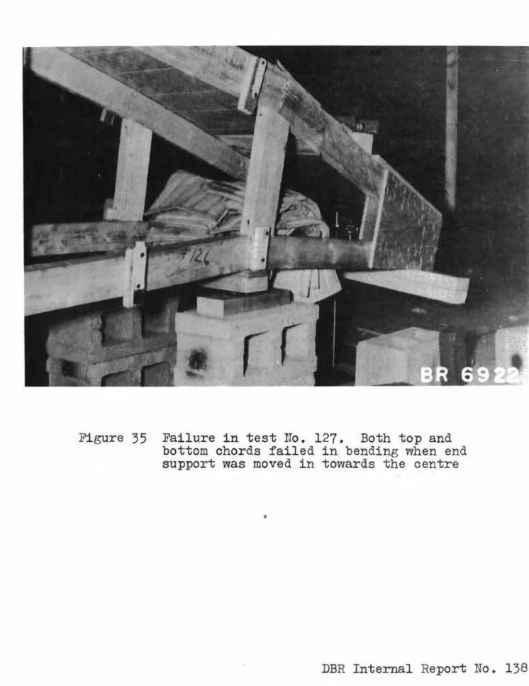
127 the roller end supports were also moved in 3 ft from the end of the span. Short struts were placed betvveen the top and bottom chords, directly over the supports, in an attempt to improve the deflection characteris-tics and strength of the truss. A dial gauge was placed to measure the deflection of the truss at the former position of the end support. The hydraulic loads were again applieduntil the structure failed (see Fig.
35).
Vertical movement of the trusses was noted at various applied loads.Recording of Results
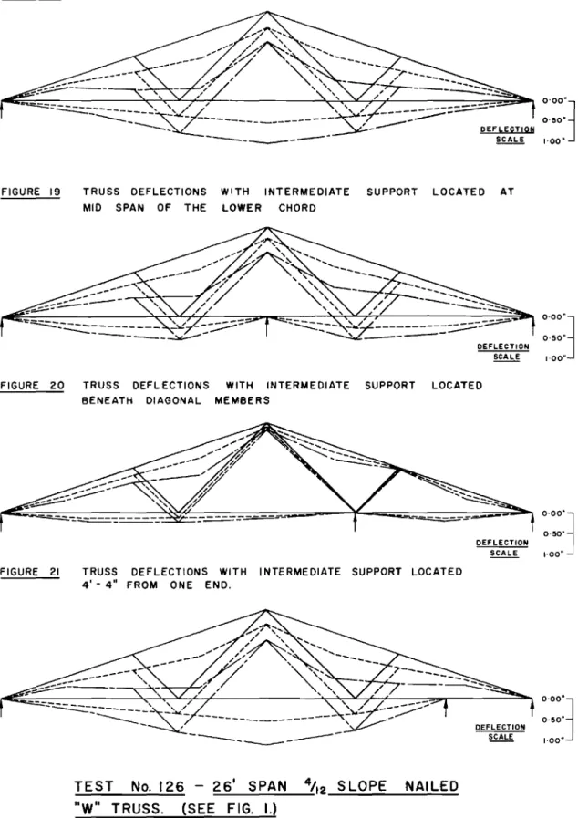
The deflection characteristics of the trusses with supports located at various positions beneath the bottom
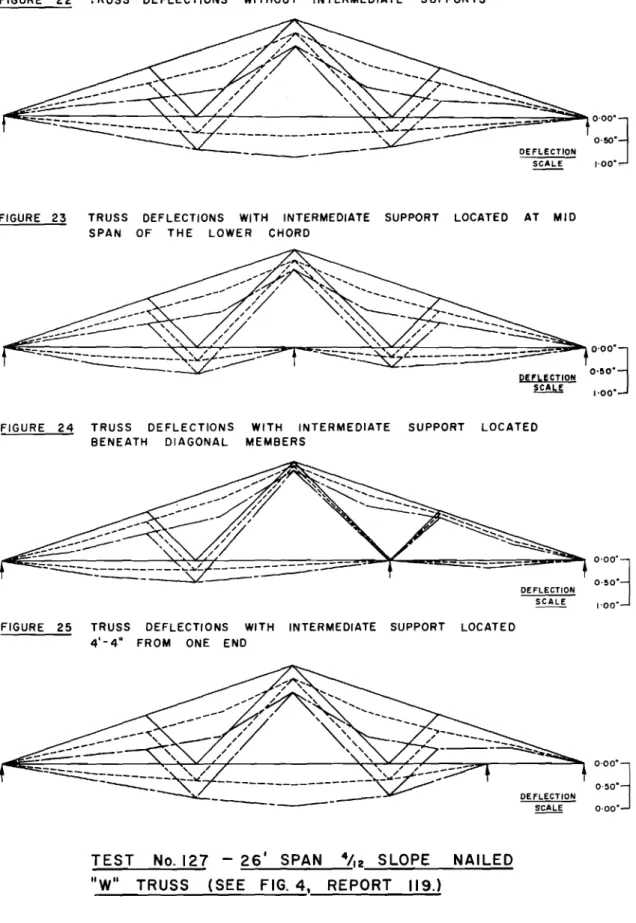
chord are shown diagrammatically in Figs. 18 to 25. A summary of the results is shown in Table V.
DISCUSSION OF RESULTS Deflections
As may be seen from Figs. 18 to 25, the location of the intermediate supports had a considerable effect on the
deflection patterns of the trusses. Although the deflections
of the trusses in test No. 127 were geIlerally less than those
in test No. 126, there was no great variation in the relative
performance of the two types. In all cases, except when the
proving ring supports were located beneath the t¥iO diagonals,
the effect of the intermediate support was such as to cause
local deflection ratios on either side of the span to be
greater than the deflection ratio of the truss without intennediate supports.
When the proving rings were located at mid span, the increase in deflection ratios on either side of the support
was not great and was ュッセ・ apparent in test No. 127 than in
test No. 126. When the proving rings were located at the
third point of the span beneath the diagonals, the deflection pattern of the trusses was considerably changed and the de-flection ratios of the segments on either side of tIlis
support were sliglltly less than for the same truss without
intennediate supports. This effect was again more apparent
in test No. 127. When the proving rings were moved to a
point
4
ft4
in. (or the end sixth point) from the endsupports, the deflection pattern of the trusses appeared to be substantially unchanged except in the immediate area of
the intermediate support. セQ・ effect of this was to decrease
the length of span over which approximately the same maximum
deflection occurred. This consequently caused a considerable
increase in the deflection ratio of the large segment. As
the end sixth point would be a fairly uncommon location for a partition, the adverse deflection characteristics produced by a partition in this location should be of little concern. Loads on Partitions
Contrary to what is sometimes thought, the partitions
below a truss will be load-bearing. The amount of load on
the partition will depend both on the type of truss and the
location of the partition. Partition location is shown in
these tests to be the more important factor. Table V shows
that the load per truss to be expected on a partition is from
65
to 50 per cent of the total applied load on the truss ifthe partition is located at the junction of the two 、ゥ。セッョ。ャウN
For other positions in the location of the ゥョエ・ャセ・、ゥ。エ・
support the load on the support varies from 7 to 16 per cent
of the total load on the trusses. It can be seen, therefore,
that the location of the partition is important in determining
the セョッオョエ of load to which the partition will be subjected.
The actual measured values for various positions of the intermediate support are recorded in Table V.
Failure Loads
In test No. 126, when the proving rings were removed and the roller end supports moved in 3 ft from the original position and the hydraulic loads re-applied, the structure collapsed at
75
psf due to the breaking of the lower chord of the truss by bending over the end support. In test No.127
when the end support was moved in3
ft from its original position and a strut placed over the support from the top of the lower chord to the bottom of the upper chord, the trusses broke at 100 psf hydraulic load due to both the upper and lower chord breaking in bending at the strut(Fig.
35).
The vertical deflections of the outer ends ofセィ・ trusses were about
t
in. per 20 psf load increment in this test.CONCLUSIONS
Although only a limited number of ッ「ウ。セカ。エゥッョウ
have been made, the following conclusions seem to be キ。イイ。ョエ・、セ
(1) Partitions located beneath a truss do 」。イセカ an appreciable percentage of the total load applied to the truss. This load varies depending upon the location of the truss and, in the more
critical positions may be greater than the load on the outside walls.
(2) The location of the partition beneath the lower chord can change the deflection pattern of the truss appreciably and may cause local deflections which produce greater deflection ratios than
would occur if no intermediate partitions were present. The increase, however, is not great and may be quite acceptable since the truss designs are conservative.
(3) The practice of cantilevering trusses of designs similar to those tested over the outside wall so that the support is considerably inside the end position may lead to greatly reduced load capacity and undesirable differential movement at the ends of the trusses. Substantial
modifications in the design of trusses may be necessary where it is not possible to support them at the ends in the normal way.
Test No. 108 109 Span (ft.) 28 28 Slope 4/12 4/12 Top Chord Size 2 x 4 2 x 4 Bottom Chord Size 2 x 4 2 x 4 Lumber I Eastern Spruce Eastern Spruce Lower Chord Deflection F.atio for 40 psf SnowLoad 1/660 1/550 %Recovery After40 pst SnowLoad Removed 74% 65% Failure Snow
! 1'YPe 01 r"aJ..Lure I (Load
psf) See Fig. 26 [I 140 See Fig. 26 124 Moisture Content at Failure Area 11% 110 28 4/12 2x 4 2x 4 Eastern Spruce 1/610 71% See Fig. 26 '140 11% 112 28 4/12 2 x 4 2x4 Douglas Fir 1/605 69% 1/290 .057 See Fig. 27 137 11% 113 114 28 28 4/12 4/12 2 x 4 2 x 4 2 x 4 2 x 4 Douglll8 Fir Douglas Fir 1/500 1/&Jo 74% 78% 1/220 1/300 .086 .070 See Fig. 28 See Fig. 26 100 115 12% 11% 121 I 122 123 26
I
26 26 4/12 4/12 4/12 2 x 4 2 x 4 2 x4 2x4 2x4 2 x 4 Eastern Spruce Eastern Spruce Eastern Spruce 1/580 1/640 1/590 72% 75% 66% 1/290 1/340 1/310 .090 .092 .056 See Fig. 26 See Fig. 29 See Fig. ::6 120 140 120 10% 10% 8% 12x6 2x6 I 2xu I 2x6 .106 .109 .027 .105 .078 .043 1/280 1/310 1/290 1/380 1/3W 1/510 See Fig. 30 See Jo'1g. 31 See Fig. 26 See Fig. 32 I See Fig. 26 Upper chords buckled ャ。エ・イ[[セャケ 65% 73% 79% &J% 66% 1/630 1/730 1/610 1/800 1/650 1/1030 I I I Douglas F1:l' Douglas Fir Douglas Fir Eastern Spruce 2 x 4 2 x 4 2 x 4 2 x 4 EasternI
I
Spruce Eastern I ISpruce 2 x 4 2 x 4 2 x 4 2 x 6 4/12 4/12 4/12 4/12 26 26 26 28 119 118 120. 115*
Lower Chord
%
Recovery Lower Chord Hon 7.onta1Span Slope Lumber Deflection After 40 psf Deflection End Hovement Failure
(ft.) Specie Ratio for 40 Snow Load Ratio for 80 at 40 psf Snow Load
psf SnOl'1 Load Removed psf Snow Load Snow Load (psf)
(ins. ) 28 4/12 Eastern 1/610 70% 1/310 .081 135 Spruce 28 4/12 Douglas 1/590 74% 1/260 .071 117 Fir 26 4/12 Eastern 1/610 71% 1/310 .079 127 Spruce 26 4/12 Douglas 1/650
66%
1/290 .098 136 Fir11ID SPAN DEFLECTIONS OF LOl''ER CHORDS
Loading Lumber Span
5_Minutes
o Ninutes 1 Hour 1 Day 1 1'i'eek 1 r.1onth
Phase Type (ft.) %Increase %Increase %Increase % Increase %Increase %Increase
Ins. Over 5 Hin. Ins. Over 5 Min. Ins. Over 5 Hin. Ins. Over 5 J·fin, Ins. Over 5 Min. Ins. Over 5 r·!in.
Deflections Deflections Deflections Deflections Deflections Deflection
-
---Trusses Loaded Eastern 23 .495---
.505 0% .505 0% .565 ' 12% .635 26% .755 50% \-lith 40 Spruce .45 .455 0% .48 5% .605 .815 126% psf snow 26---
33% 79% rto°3 load, 5 psf dead roof load I and 10 Douglas 28 .C45 --- .65 0% .675 4% .815 26% 1.02 57% セNSSU 105% psr ceiling Fir 26 .475 --- .48 0% .49 2% .53 10% .62 29% .76 58% loadIns. % Recovery Ins. %Recovery Ins. %Recovery Ins. % Recovery Ins. %Recovery Ins. %Recovery
28 .30 60% .30 60% .28 63% .26 66% .235 69% .175 77% Eastern All Spruce 26 .C4 38% .63 39% .615 40% .59 43% .53 49% .48 53% Loads Dourlas 28 .715 46% .715 46% .69 48% .C45 52% .61 54% .53 60% Removed Fir 26 .34 55% .33 57% .325 57% .30 61% .255 66% .215 72%
SmWN IN FIG. 1 TO
4
AHOUNT OF MATERIALS LABOUR TIME ide
SpanI Slope
2"x4
11(fbm)
nails Cuttinp' hours
) Structural Plywood Pieces IPlates .93 .98 .68 .73 .77 .56 .63 .66 .77
.77
.77 .11 .17 .17 .17 .17 .17 .17 .17 .17 .10 .08 .08 .08 .10 .08 .12 .08 .08 2.72 3.06 3.06 2.93 3.06 2.24 2.512.64
3.06 12.1 10.9 12.8 12.3 12.1 12.1 12.1 12.8 12.364
36 2824
I
4/12I
47 26 I 4/12I
51 28 I 4/12I
55 24I
5/12I
49 26 , 5/12I
52 28 I 5/12I
56 RXセヲM I 4/12 I 31 RセJJQ 4/12 I 37 28:t I 4/12 I 13*
l'Jith 211x6" top chord and 2"x4" bottom chord.**
With 211xh"
top chord and 2"x6" bottom chord.:t Hith 211x611 top and bottom chords.
Jck Labour time is calculated on the basis of observations on the 261 and 281 spans
(4/12 slope). Assembly time is based on spruce trusses. For dッオセャ。ウ fir
trusses assembly time was appr-ox,
5
minutes less per truss because fe'trernails were used.
1.02 .81
I
.88 I .91I
1.04
I
1.04
I
WITH INTERMEDIATE SUPPORTS
Position Applied Averae;eLoad on AverageMaximum
Test of sno« Each Deflection Ratio
No. Proving Load Proving For any Segment
Rings (psf) Ring (lb.) of Bottom Chord
Before 40
-
1/570 Proving Rings 80--
1/300 Installed No. 126 At Centre 40 440 1/560 of Span 80 750 1/280 (see Fig. 1) At Third 40 1800 1/720 Point of 1/530 Span 80 2900 4'-41 ' 40 240 1/380 From End 1/187 of Span 80 410 Before 40--
1/710 Proving Rings 80--
1/350 Installed At Centre 40 360 1/600 No. 127 of Span 80 640 1/300 (see Fig. 4) (Report 119) At Third 40 1400 1/740 Point of Span 80 2500 1/330 4' -4" 40 210 1/440 From End of Span 80 360 1/22024'°4 25 23 5 7 I II
21'· 4" 2T U 5 I 10 17
28'·4- U 2T 5
•
10 I '12"
!i2..!.! - TO ENSURE MAXIMUM STIFFNESS, THE UPPER CHORDS
MUST 8E IN GOOD BEARING CONTACT AT THE PEAK.
LONG DIAGONAL
24"
!:..!!.!!!.!.!! - C.L.A. No.I EASTERN SPRUCE OR M.L.'. NO.4 EASTERN SPRUCE.
PLYWOOD- ALL PLATES ARE 'Ii SHEATHING
GRADE DOUGLAS FIR PLYWOOD.
!!!.!..!:.!--ALL NAILS - 3" COIIMON.
ALL ROWS OF NAILS ARE STAGGERED
IN THE DIRECTION OF GRAIN TO KEEP SPLITTING TO A IIINIMUII.
,0VEItMANG TO OISiReO LENGTH.
26'-4" 22 I 20 I 5 I 7 I
,
I 14 I -28'-4"1 24 I 22 I 5 I T I,
I 15 OVERHANG TO DESIRED LENGTH ,LOIlG DIAGONAL 12" I." '(MAY BE DECREASED TO 12" FOR 24' SPAll)NOTE - TO ENSURE MAXIMUM STIFFIlESS, THE UPPER CHORDS MUST BE IN GOOD BEARINI CONTACT AT THE PEAK,
LUMUR- C.L.A. No.1 EASTERN SPRUCE OR M.L.B No.4 EASTERN SPRUCE.
PLTWOOO- ALL PLATES ARE l/t" SHEATHINI GRADE DOUGLAS FIR PLYWOOD NAILS - ALL NAILS - 3" COMMDN
ALL ROWS OF NAILS ARE STAGGERED IN THE DIRECTION OF THE GRAIN TO KEEP SPLITTING TO A MINIMUM.
24'-4- 14 13 3 4 6 8 2f!t-4- 15 14 3 5 7 9 281 4 -16 15 4 5 7 10 L,4 I
I
12"I
I
12" • • セ 24 セ --, \ . - - I ..:.: LA 201 I 4"I
'"
.1.
'"
-I"[-"\--
'"
I
"'-J : L i :I
SHORT \DIAGONAL ", LONG OVERHAN. TO
DIAGONAL DESIRED L£NGTH
NOTE - TO ENSURE MAXIMUM STIFFNESS, THE UPPER CHORDS
MUST BE IN GOOD BEARING CONTACT AT THE PEAK.
LUMBER - CONSTRUCTION GRADE
- DOUGLAS FIR.
PLYWOOD - ALL PLATES AFiE 1." SHEATHING
GRADE DOUGLAS FIR PLYWOOD.
セ - - ALL NAILS - 3" commonセ
ALL ROWS OF NAILS ARE STAGGERED
IN "'HE DIRECTION OF GRAIN TO KEEP SPLITTING TO A minimuBセ
24"4"
..
..
S S 7 II2S·-.- IB 17 4 S 7 II
28'.4"
"
18 4 I I 12L
NOTE - TO ENSURE MAXIMUM STIFFNESS, THE UPPER CHORDS
MUST BE IN GOOD BEARING CONTACT AT THE PEAK.
LONG DIAGONAL
LUMSER -CONSTRUCTION GRADE
DOUGLAS FIR
PLTWOOD- ALL PLATES ARE '/2" SHEATHING
GRADE DOUGLAS FIR PLYWOOD.
NAILS --ALL NAILS - 3· COMMON
4LL RO.WS OF NAILS 4RE STAGGERED IN THE DIRECTION OF THE GRAIN TO KEEP SPLITTING TO A MINIMUM.
OVERHANG TO
DESIRED LENGTH.
o
«
o ..J 120 iMMMMKMMMiMMMMMNNNNNZG\iMMMMKMLNNNMNMセM ___ + _ -セ o z (J) 80QMMMMKMMKMMWBGWセfMMᆳ o UJ ..JIt
40I---_+__«
I
セMMMKMMMエMMMN
I (TESTS CEILING)0, .1-
+ - - - - + - - - + - - - - 1 LOAD L -'00 ·40 -80 '-20 1'60 2-00 2'40 2'80MID SPAN DEFLECTIONS, LOWER CHORD (IN.)
FIGURE 5
LOAD VS. DEFLECTION CURVES 281
SPAN NAILED 'IW" TRUSS 4t.2 SLOPE. SPACED 21- 0" O.C.
EASTERN SPRUCE. (2)( 4 TOP AND BOTTOM
CHORDS 2 00イMMセMMイMMLNNNNMMNNNNNLNNNNNNNNNNNNNLNNNMLNNNNMMセMMイMLNNNNMMNNNLNNNNNNNNNNNNNLNNNMLMMMNNNLNNNNNNNNNL
-
u;en
セ 1601 _ _ - - + - - - I - - - t - - - t - - - + - - - I - - - - 1 o«
o ..J 120 1__--+---I----=--t---t---"'k;--___I___---1 セ o z (J) 80 i⦅⦅MMKMMMiMMMMセBGfMMセエMMMMMMKMMMMMiMMMMMャ o W ..J a. セTPQMMMMKセセMKMMMMエMMMMMMBG]MMMエMMMMMKMMMiMMMMMMMMi CEILING)0 LOA 0 'l...--I£;...J...---'-_"'--....I----l._..._ l . . . . -...---l._"'--...---l---' ·00 ·40 '80 1·20 1·60 2·00 2'40 2·80MID SPAN DEFLECTIONS, LOWER CHORD (IN.)
FIGURE 6
LOAD VS. DEFLECTION CURVES 281
SPAN
NAILED ..
w..
TRUSS 4"2 SLOPE, SPACED2'-0" O.C. DOUGLAS FIR. (2)(4 TOP AND
. I o c:( o ..J 120 セ o z (/) 8 0 QMMMMMMMMKMMM|MMKKWGセKMャイ⦅⦅⦅ ---+---1---+---1 o lIJ ..J Q. 40 Q. c:( a:160
-CEILINGCO
LOAD MMセ ...__J..--.-;...I.._...l____l_...l.._..._L._...J...l._..1._...I..._l..._...J ·00 ·40 '80 1·20 1-60 2'00 2'40 2·80MID SPAN DEFLECTIONS, LOWER CHORD UN.)
FIGURE 7
LOAD VS. DEFLECTION CURVES 26' SPAN
NAILED lOW" TRUSS TセR SLOPE, SPACED
21 - 011 O.C. EASTE RN SPRUCE. (2)(4 TOP
AND BOTTOM CHORDS,)
i
No. 118,119, 120J -o lIJ ..J Q. 4 0 1---..>--tF--Q. c:( o3
120----+---1----+
セ o z (/) 80-
u.:en
!:
1601 - - - + - - - - + - - - - 1 - - - { - - - + - - - + - - - I CEILINGrO -LOAD セQcNNMNNNNNjNNNNNNNNNNNNャN⦅NNNャNNNMNNNNNャ⦅⦅lNNNN⦅NNNャNN⦅ ..._L._...J...l._..1._...I..._L....__I '00 '40 -80 1'20 1'60 2'00 2'40 2'80MID SPAN DEFLECTIONS, LOWER CHORD (IN.)
FIGURE 8
LOAD VS. DEFLECTION CURVES 26' SPAN
NAILED "WII TRUSS TセR SLOPE, SPACED 2'-011 O.C. DOUGLAS FIR. (2)( 4 TOP
.... ..,.... ... ... .<. AVG.
of
3 TEST ... ;,;,,,,,;,o
w
-
セ4 0
エMMMMMゥhiセセMMMKMMM⦅K⦅MMK⦅MM⦅⦅ャMMN⦅⦅K⦅MM⦅⦅⦅i Q.<t
o
<t
3
12
0
エMMMMMKMMMMMKMMMMMMN[セセセ⦅K⦅⦅M⦅⦅ャ⦅MMMャMMMM⦅⦅⦅i3:
o
セ
80
--
IL.
(/) n;160
エMMMセMMMMKMMMMKMMM⦅K⦅⦅MヲMセヲMMMK⦅MMKMNNBNN・⦅⦅MMMMi CEILINGjOLOAD L-K...-""""---"-_..I..-...&-_L.--""O"'-..._...l....-...L...----l_... """'-....I
-00
-40
-80
1-20
1-60
2·00
2·40
2-80
MID SPAN DEFLECTIONS, LOWER CHORD (IN.)
LEGEND:
115
116
117
-AVG
-211X6" TOP CHORDS 2"x
4" BOTTOM CHORDS 211x
411 TOP CHORDS 211x
6" BOTTOM CHORDS 2"x
6" TOP CHORDS 2"x
6" BOTTOM CHORDS 2"x
411 TOP CHORDS 211x
411 BOTTOM CHORDS FIGURE 9LOAD VS. DEFLECTION CURVES
28'
SPAN NAILED"W" TRUSS 4/12 SLOPE, SPACED 21 - 0 " O.C.
MZGZZZZGZZGZZGZZZZZZZZGZZGZZGZZGZBMMBGM]]]MGMセGMセセセOGZ⦅MMMMMMMMMMMMMMMMMMMMMM セセセM Mセ ,
---
DEFLECTION SCALE:.:::J
,.00"J
FIGURE II' DOUGLAS FIR, 28' SPAN "l12 SLOPE. (TESTS No.112,113,114.)
FIGURE 12: EASTERN SPRUCE, 26' SPAN 4/12 SLOPE. (TESTS No. 121, 122, 123.l
:·.::::l
I'OO"J
:.::J
I'OO"J
FIGURE 13: DOUGLAS FIR, 26' SPAN 4/12 SLOPE. (TESTS No. 118, 119,120.1
:'::J
I'OO"J
DEFLECTION
LEGEND:
CHARACTERISTICS OF NAILED " W" TRUSSES.
SHAPE OF TRUSS BEFORE APPLICATION OF LOAD.
--- AFTER APPLICATION OF 40 P.s.F. ROOF LOAD AND
10 P.s.F. CEILING LOAD.
--- AFTER APPLICATION OF 80 P.S.F; ROOF LOAD AND
FIGURE 15' EASTERN SPRUCE, 2"x4" TOP CHORDS, 2"x6" BOTTOM CHORDS. (TEST No. 116.)
DEFLECTION SCALE
FIGURE 16' EASTERN SPRUCE, 2" x 6" TOP CHORDS, 2"x 6" BOTTOM CHORDS. (TEST No.lI7.l
- - ::::;:::::.==--;.-;;:..- - -
==--=--DEFLECTION SCALE
DEFLECTION CHARACTERISTICS, NAILED " W" TRUSS - 28' SPAN セR SLOPE,
LEGEND'
SHAPE OF TRUSS BEFORE APPLICATION OF LOAD.
O'OO'j 0'50' 1'00'
:::J
I'OO"J::::J
I'OO.J AFTER 10 P.S.F. APPLICATION OF 40 P.S.F. CEILING LOAD.ROOF LOAD AND
AFTER APPLICATION OF BO P.S.F. ROOF LOAD AND 10 P.S.F. CEILING LOAD.
1000HR 100HR
IHR
セャ
ALL TRUSSES MADE WITH 2" x 4" MEMBERS
•
J
(D-26' SPAN 4/12 SLOPE, EASTERN SPRUCE.
-V
I
@-26' SPAN 4/12 SLOPE, DOUGLAS FIR.
V
@-28' SPAN TセR SLOPE, EASTERN SPRUCE.
V
@- 28' SPAN 4/
12 SLOPE, DOUGLAS FIR.
V
I I .A セセ セ , セv セセ セV
,.
セ l.'セO
, 10-'-セ...V
セ I , -セセ
セセイ
1.
iMGセ[
セセ
セ セ I--'I-" セ P-== セ l.o't::e:
J
i ",,>""
l.'-
I-
-
"", ...-J I---::::::;
-
-
... セ"1
I
-
:::
-
-" _0r-6- -_ 0 iセ - 0 w ";:I I I I , I '00o
a:: ILl セ セ '80' oi
'20' o a:: o , :z: 1-00"
.
V) z o...
" '60' ILl -l U. ILl o 2 ·40' <[ c, V)i
1-20' 10HRDURATION OF LOAD (HRI
FIGURE
17
DEFLECTION
VS
TIME
CURVES
FOR
VARIOUS
NAILED
"w"
TRUSSES
LOADED
WITH
40 RS.F:
SNOW
LOAD, 10 RS.F. CEILING
::::J
I'OO·J
FIGURE 19 TRUSS DEFLECTIONS
MID SPAN OF THE
WITH INTERMEDIATE
LOWER CHORD
SUPPORT LOCATED AT
FIGURE 20 TRUSS DEFLECTIONS WITH INTERMEDIATE SUPPORT LOCATED
BENEATH DIAGONAL MEMBERS
DEFLECTION SCALE O'OO"j 0·50" 1'00' O'OO'J 0·50' 1'00" FIGURE 21 TRUSS 4' - 4" DEFLECTIONS WITH
FROM ONE END.
INTERMEDIATE SUPPORT LOCATED
DEFLECTION SCALE
::::J
I'OO ..
J
TEST No. 126 - 26' SPAN 4/12 S LOPE NAILED
" W" TRUSS. (SEE FIG. I.)
LEGEND:
SHAPE OF TRUSS BEFORE APPLICATION OF LOAD.
--- AFTER APPLICATION OF 40 P.S.F. ROOF LOAD AND
10 P.S.F CEILING LOAD.
- - - - _ . AFTER APPLICATION OF 80 P.S.F. ROOF LOAD AND
O'OO'j 0'50'
"00'.
FIGURE 23 TRUSS SPAN
DEFLECTIONS WITH INTERMEDIATE OF THE LOWER CHORD
SUPPORT LOCATED AT MID
O'OO'j OoSO'
1'00'
FIGURE 24 TRUSS DEFLECTIONS BENEATH DIAGONAL WITH INTERMEDIATE MEMBERS SUPPORT LOCATED FIGURE 25 TRUSS 4'-4" DEFLECTIONS WITH FROM ONE END
INTERMEDIATE SUPPORT MMMセMZZM DEFLECTION SCALE LOCATED DEfLECTION SCALE O'OO"j O'SO' "00' O'OO'j 0'50' 0'00'
TEST No. 127 - 26' SPAN 4/12 SLOPE NAILED
"W" TRUSS (SEE FIG. 4, REPORT 119.)
LEGEND:
SHAPE OF TRUSS BEFORE APPLICATION OF LOAD. AFTER
10 PS.F.
APPLICATION OF 40 PS.F. CEILING LOAD.
ROOF LOAD AND
AFTER 10 PS.F
APPLICATION OF CEILING LOAD.
on the side next to the t ru s s
heel gusset plate causing the top chord to break in bending
•
points
rr
Figure
35
Failure in test No. 127. Both top and bottom chords failed in bending when end support was moved in towards the centre•