HAL Id: tel-00940151
https://tel.archives-ouvertes.fr/tel-00940151
Submitted on 31 Jan 2014HAL is a multi-disciplinary open access archive for the deposit and dissemination of sci-entific research documents, whether they are pub-lished or not. The documents may come from
L’archive ouverte pluridisciplinaire HAL, est destinée au dépôt et à la diffusion de documents scientifiques de niveau recherche, publiés ou non, émanant des établissements d’enseignement et de
Avulsion process : stratigraphic and lithologic records
-Application to the Amazon and Zaïre turbidite systems
Sandra Manson
To cite this version:
Sandra Manson. Avulsion process : stratigraphic and lithologic records - Application to the Amazon and Zaïre turbidite systems. Stratigraphy. Université de Bretagne occidentale - Brest, 2009. English. �tel-00940151�
THÈSE / UNIVERSITÉ DE BRETAGNE OCCIDENTALE
sous le sceau de l’Université européenne de Bretagne
pour obtenir le titre de
DOCTEUR DE L’UNIVERSITÉ DE BRETAGNE OCCIDENTALE
Mention : très honorable
École Doctorale des Sciences de la Mer - Géosciences Marines
présentée par
Sandra Mansor
UMR-CNRS 6538 “Domaines Océaniques”, IUEM Laboratoire Environnements Sédimentaires, Ifremer
Le processus d’avulsion :
Enregistrement stratigraphique et sédimentologique - Application aux éventails turbiditiques de l’Amazone et du Zaïre
Avulsion process :
stratigraphic and lithologic records -
Application to the Amazon and Zaïre turbidite systems
Thèse soutenue le 19 novembre 2009 devant le jury composé de :
Michel Lopez, Rapporteur
Professeur à l'Université Montpellier 2
Tadeu dos Reis, Rapporteur
Professeur à l'Université d'Etat de Rio de Janeiro
Christophe Delacourt, Examinateur
Professeur à l'Université de Brest
Mike Sweet , Examinateur
Chercheur à ExxonMobil
Nathalie Babonneau , Examinateur
Maître de Conférence à l'Université de Brest
Bernard Dennielou, Tuteur (remplacement de Bruno Savoye)
Chercheur à Ifremer
Laurence Droz, Directrice
« Si on se limite à décrire la réalité, on ne rencontre aucun
obstacle. Mais le problème consiste bien plus à repérer en
elle ce qui a du sens pour nous, ce qui est surprenant dans
l’ensemble des faits. Si les faits ne nous surprennent pas,
ils n’apporteront aucun élément nouveau pour la compréhension
de l’univers : autant donc les ignorer ! » (René Thom,
Paraboles et catastrophes)
Acknowledgment - Remerciements - Danksagung
Mon travail présenté dans ce mémoire a été effectué au Laboratoire des Environnements Sédimentaires du département Géosciences Marines d’Ifremer (Institut français de recherche pour l’exploitation de la mer) et au Laboratoire des Domaines Océaniques - UMR 6538 - de l’IUEM (Institut Universitaire Européen de la Mer) à Plouzané en France. Cette thèse s'inscrit dans une collaboration académique et industrielle et a été cofinancée par le partenaire industriel ExxonMobil. J’ai eu également l’opportunité de passer un séjour de trois mois au sein de l’équipe « Stratigraphy Core Group » d’ExxonMobil Exploration Company à Houston, Texas aux Etats-Unis.
Je remercie les collègues, qui à divers titres et en diverses circonstances m’ont accueilli et qui ont su me faire bénéficier de leur expérience.
J’exprime mes sincères remerciements à Laurence Droz et Bruno Savoye qui m’ont permis d'apprendre, d'avancer et de réaliser cette thèse.
Je remercie aussi les membres du jury de m’avoir donné l’occasion de défendre ce travail au cours de ma soutenance de thèse.
Mes meilleures pensées et toute ma reconnaissance à tous ceux, amis ou famille, qui m’ont accompagné ou qui ont marqué mon chemin.
Un mot à Norah et Hervé : Danke.
Et des pensées particulières pour Bruno et sa famille.
Table of contents
Table of contents
Introduction……… 1
Chapter I – A review of sediment transport in deepwater………..……… 7
I.I Turbidity currents: the main mechanism for sediment transport in turbidite systems……….. 9
1.1 Turbidity currents……….. 9
1.2 Turbidites………...……….11
I.2 Deep-sea fans……….………... 12
2.1 Models……….………13
2.2 Depositional elements and involved processes………... 16
2.2.1 Leveed channels……….…………... 16
2.2.2 Levees………. 16
2.2.3 Frontal splays or channel-mouth lobes……….. 18
2.2.4 Crevasse splays………..………... 22
I.3 HARPs and avulsion process……….……. 24
3.1 The Amazon Fan avulsion models………. 25
3.1.1 Channel-levee and basal HARPs: first avulsion model (Flood et al., 1991)…………. 25
3.1.2 Lithology of the HARPs (ODP Leg 155)………. 28
3.1.3 Equilibrium profile and nature of sediment supply (Pirmez et al., 2000)………...29
3.1.4 Internal seismic structure and refined model related to equilibrium profile through time (Lopez , 2001)…………..31
3.2 HARPs in other fans……….…….... 33
3.2.1 The Zaïre Fan………... 33
3.2.2 The Danube Fan……….... 36
3.2.3 The Bengal Fan……….. 38
Chapter II – Geological Background of the Amazon Fan………..……. 41
II.1 A long-term study……….. 43
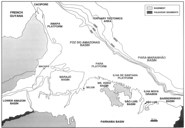
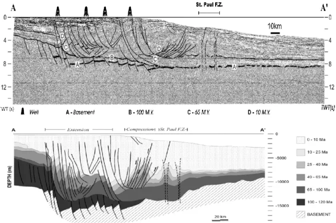
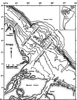
II.2 The Foz do Amazonas Basin……….. 44
II.3 The Amazon River and the continental shelf………..…. 48
II.4 The Quaternary Amazon Fan………. 52
4.1 The main domains of the fan………... 52
4.2 The Amazon channel……… 54
4.3 Architecture of the fan……….…. 55
4.4.1 18O isotopic ages……… 59
4.4.2 Biostratigraphy……… 60
4.4.3 Age model for the Amazon Fan based on 18O evolution and biostratigraphy…...61
4.4.4 Age model based on radiocarbon datings……… 63
4.4.5 Deposition rates and channels duration………. 64
4.5 Sediment distribution……… 65
4.5.1 Sedimentary facies observed during ODP Leg 155………. 66
4.5.1.1 Levees……….. 68
4.5.1.2 Channel-fill deposits………... 71
4.5.1.3 HARPs deposition……….. 73
4.5.1.4 Regional MTDs……… 74
4.5.2 Sediment distribution in the lower fan and terminal lobes from Lobestory cores.……….. 76
4.5.3 Electrical and sedimentary facies……… 77
4.6 Characteristics of the turbidity currents in the Amazon Fan……….. 79
Chapter III – The Amazon Data and Methods……….……... 81
III.1 The data set……….. 84
1.1 Geophysical data……….. 84
1.1.1 2D high-resolution seismic data………..…. 84
1.1.1 3.5 kHz seismic data………. 85
1.1.1 EM12Dual bathymetric and acoustic data………. 85
1.2 Geological data: lithology and wireline data from ODP Leg 155………... 86
1.2.1 Drilling sytem……….. 86
1.2.2 Wireline log data………. 86
III.2 Interpretation methods……… 87
2.1 Seismic data analysis………... 87
2.1.1 Criterias for seismic facies classification……… 88
2.1.2 Interpolation of depositional systems……….. 89
2.2 Lithostratigraphy……… 89
2.2.1 Correlation of seismic units interpreted in this study with ODP lithologic units……… 90
2.2.2 Refined lithologic description of specific intervals………. 91
2.2.3 Interpretation of diagraphic logs to fill voids at specific intervals……… 92
2.2.4 Validity of the age model……….. 96
Chapter IV – The Quaternary Amazon Fan revisited………... 103
Table of contents
1.1 Seismic facies analysis……… 105
1.1.1 High-amplitude facies (A)………. 105
1.1.2 Medium to low amplitude facies (B)……… 107
1.1.3 Low amplitude facies………. 108
1.2 Internal structure of the turbiditic elements………... 108
1.2.1 Internal architecture of the HARPs……….. 109
1.2.2 Internal architecture of the levees………... 112
1.2.3 Conclusions………. 115
1.2.3.1 The avulsion lobes……….. 115
1.2.3.2 The levees………... 116
1.3 Refined channel map and HARPs distribution………. 117
1.3.1 Refined architecture……….. 121
1.3.1.1 The HARPs X and Orange-1 systems………. 122
1.3.1.2 The Aqua-Nouveau Brown groups of channel-levee systems………. 126
1.3.1.3 The 1F, 1E and 1D to 1A groups of channel-levee systems……… 129
1.3.2 3-D characteristics of the HARPs……….... 131
1.3.2.1 The paleomorphology at the beginning of ULC channel-levee deposition in the Lobestory area………….. 131
1.3.2.2 The HARPs X……….. 134
1.3.2.3 The Orange-1C and Orange-1B HARPs………. 134
1.3.2.4 The Aqua HARPs……… 136
1.3.2.5 The Brown HARPs……….. 137
1.3.2.6 The 1D HARPs……… 138
1.3.3 Conclusions and discussion………. 139
IV.2 Lithological input to HARPs and levee sediment content from ODP drillings……….….. 142
2.1 Lithology of the HARPs……… 142
2.1.1 The Orange-1 B HARPs………... 142
2.1.2 The Aqua HARPs……….. 146
2.1.3 The Brown HARPs………. 147
2.1.4 The 1D HARPs………... 150
2.1.5 HARPs X……….153
2.2 Lithology of high-amplitude parts in the levees……… 154
2.3 Conclusions……… 157
2.3.1 Lithology of the elementary units of the channel-levee basal HARPs………...157
2.3.2 Lithology of the HARPs X………. 158
3.1 Ages of the studied channel-levee systems………. 159
3.2 Longitudinal evolution of the Brown channel-levee-HARPs system: Pure aggradation or aggradation/progradation?... 162
IV.4 Conclusions……….. 165
Chapter V – First and last steps of the avulsion: Inputs from the Zaïre Fan……… 167
V.1 Introduction to the Zaïre Fan study……… 169
V.2 Previous work: Architecture of the Zaïre Fan……….. 169
2.1 Channel-levee complexes………170
2.2 Individual channel-levee systems……….. 171
2.3 Channel-avulsion and high-amplitude units………. 174
V.3 Is the Zaïre Fan comparable to the Amazon Fan?... 175
V.4 Inputs of the Zaïre Fan to the knowledge of the avulsion process……….. 178
4.1 Location of the studied channel-levee system………. 178
4.2 Data set……….. 179
4.3 Morphology of the channel-levee systems……… 181
4.4 The first steps of an avulsion……….. 182
4.4.1 Crevasse splays on the right levee of A16……….182
4.4.2 Levee breach by local MTD on the right levee of Channel S3………184
4.5 The onset of the new channel……… 185
4.6 Conclusions……… 189
Chapter VI – Synthesis and conclusions……… 191
VI.1 Main conclusions and discussion………. 193
VI.2 Synthesis: towards a conceptual model……….. 195
VI.3 Limits of our model and perspectives……….. 200
References……….. 203
Introduction
3 As rivers flow across the landscape they pick up and transport sediments, ranging from pebbles to very fine sand and mud. Part of the sediments is deposited upstream, part will continue downstream and as rivers reach the sea, sediments will be deposited at the estuaries (Figure 1). Depending of the local physical conditions of currents, tides and waves, sediments will be washed away from the river mouth, moved along the coast or out to the sea, or the sediment may build up lagoons, barriers islands or deltas.
Figure 1: Amazon River estuary (source Wikipedia, screenshoot taken from NASA’s globe software World Wind)
A component of the sediment will be transported further into the basin by a variety of gravity-driven processes (Figure 2) on the slope: slumps or debris flows (non-channelized systems) or avalanches or turbidity current along an incised canyon or a network of canyons (channelized systems). At the base of the continental slope, where canyons end, a deep sea fan can be formed.
Major deep-sea fans have been built from vertical and lateral stacking of the following elements with associated features, interspersed with mass-flow deposits:
- Channels, serve as pathways for turbidity currents and other sediment-gravity flows to transport and deposit sediments further in the deep-sea,
- Levees representing sediments coming from overflow currents of the channels, - Lobes, representing sediments deposited in lobate bodies, mainly at channel-ends. The distal lobes are the areas where sediments end their travel from the continent.
Figure 2 : Gravity processes on passive margins (Shanmugam, 2000).
This study will be focused on Avulsion, one of the “end of chain” processes of sediment transport and deposition from continent to the deep basins, explaining the distribution of depocenters and the sediment partitioning in deepwater, provoking the abandonment of a channel and the birth of a new one. This process is mentioned since the 50s, where migration of a turbidity-current channel to some less elevated sector (Figure 3) is suggested in analogy to subaerial stream channel. Low levee sides, interpreted to result from the influence of the Coriolis force, are suggested to favor the breaking out of the turbidity currents (Menard, 1955).
Beside the analogy to subaerial channels, the first true indicator of avulsions in deepwater was the detection of the HARPs, a seismic term, firstly introduced by Flood et al. (1991). HARPs are packets of high-amplitude reflectors at the base of channel-levee systems. HARPs were suggested to be sandy deposits and related to the avulsion process in deep-sea fan environments because of their disposition in lows adjacent to the breached parent channel. The avulsion process concerns the sediment distribution associated with channel shifting within channel-levee complexes.
Therefore, avulsion is an important process controlling the architecture of deepwater deposits and understanding the avulsion process in deepwater is the aim of this thesis.
Introduction
5
Figure 3: Diagram showing the development of a channel (channel 1) by avulsion of the parent channel (channel Aqua) (Flood et al., 1991).
Besides of their academic interest, these studies also bear an applied interest because they are potential areas for hydrocarbon reservoirs. Even though most of the world has begun a transition from conventional oil and gas energy toward alternative energy sources, it is expected that the means of world energy survival will still depend on hydrocarbon supplies for probably the next century (Halbouty, 2001).
Framework of this thesis
During the last 30 years, study of the continental margins has been one of the main research objectives of IFREMER’s and Laboratoire Domaines Océaniques, while the oil industry has been increasingly focusing on deep-offshore energy resources (Pettingill and Weimer, 2002). At the end of 1997, IFREMER and TOTAL launched a 5-years research program devoted to studying the continental margin seaward of Gabon, Congo and Angola, with particular emphasis on exploring the huge submarine valley network carved in the ocean floor offshore the Congo River mouth. The ZaïAngo project, under the leadership of B. Savoye, was intended to study, at a regional scale, the recent Zaïre (Congo) fan in order to acquire an integrated regional understanding of sedimentary processes controlling the distribution and the characteristics of the reservoirs, from the river mouth to the distal areas. Different studies have been undertaken about the overall fan stratigraphy and channel avulsions (Droz et al.,
2003), the morphology of the present canyon and channel system and sedimentary processes (Migeon, 2000, Babonneau, 2002, Gervais et al., 2001, Migeon et al. 2004, Bonnel, 2005).
Based on the Zaïre experience, a new project has been realized on the Amazon Fan in 2004 (Lobestory cruise) under the responsibility of B. Savoye.
The aim was to acquire complementary data of this zone in order to find answers to questions that were addressed by the results of the Zaïre Fan and the state-of-the art knowledge about deep-sea fans in the academic world, concerning in particular: (1) the distal lobes, a domain that remained unknown at that time and has now been studied by Jégou (Jégou, 2008; Jégou et al., 2008) in the framework of her thesis, (2) the avulsion process, which is associated to the HARP deposits and is one of the main cause for the lateral distribution of sediments.
The avulsion process has been studied in my work funded by ExxonMobil, under the tutoring of B. Savoye and L. Droz.
The Amazon Fan is one of the biggest and most studied deep-sea fans of the world. But despite these works, the avulsion process remained insufficiently understood. Kolla (2007) mentioned in a paper reviewing channel avulsion patterns in some major deep-sea fans, that “in the Amazon Fan is felt that existing published ODP data (Flood and Piper, 1997) need to be re-examinated in order to evaluate whether or not extra- or intra-basinal factors affected timing of specific channel avulsions”.
The Lobestory campaign in 2004, acquired high-resolution data on the Quaternary Amazon Fan, crossing 9 ODP sites, with the aim to re-evaluate the lithostratigraphic recording of ODP and to describe at a smaller seismic scale the famous HARPs of the Amazon Fan.
The combination of the ODP drillings and the newly acquired high-resolution multichannel seismic data has made the Amazon Fan an ideal study area to refine the avulsion model proposed by Flood et al (1997).
We also studied the avulsion process in the Zaïre Fan, comparable in size to the Amazon Fan because previous studies had shown that early stages of channel avulsion were probably observed.
The two fans revealed complementary observations that allowed to highlight some new findings and to propose a refined model for the avulsion process.
-Chapter I-
A review of sediment transport in
deepwater
Chapter I – A review of sediment transport in deepwater
9
1 TURBIDITY CURRENTS: THE MAIN MECHANISM FOR
SEDIMENT TRANSPORT IN TURBIDITE SYSTEMS
Investigation of deep-sea sediments began with the voyage of the Challenger (1872-1876) which established the general morphology of the ocean basins, published by Murray and Renard (1891). Oceans were considered to have quiet, undisturbed floors where only pelagic and hemipelagic sediments were deposited. All sandstones were thought to have been deposited in shallow waters. Today we know, thanks to studies of the last century about deep-sea sedimentation, that morphologies on passive margin slopes are a result of a combination of pelagic settling, bottom currents accumulations and gravity flow deposits that are able to transport coarse sediments to the deep-sea.
1.1 TURBIDITY CURRENTS
Gravity flows have been well studied (e.g. Middleton and Hampton, 1973; Lowe, 1982; Mulder and Cochonat, 1996; Shanmugam, 2000; Stow and Mayall, 2000) and can be classified into three main groups: (1) mass movements (creeping, slides and slumps), (2) laminated or plastic flows (debris flows, grain flows, fluidized flows, liquefied flows), (3) turbulent flows (turbidity currents) that deposit turbidites. It is generally accepted that turbidites are the most common deposits in the deep-water clastic systems (Stow and Mayall, 2000). Turbidity currents are mixtures of sediment and water, which move under gravity due to the density contrast with the less dense medium of seawater or fresh water. They are also less dense than debris flows and hence have a higher Reynolds number.
The turbidity current concept was introduced by Kuenen and Magliorini (1950) in their paper “Turbidity currents as a cause of graded bedding”. Previously to the in-situ observations or records of these currents (e.g. Shepard et al., 1977), they were inferred from observations of breaks of submarine telegraph cables (Heezen and Ewing, 1952). The period from the 1950 to the 1980s was a time of conceptual model building for the deposits of turbidity currents. Models are constantly re-evaluated by new findings from deep-water sedimentology and sequence stratigraphy research.
The anatomy of gravity currents, including turbidity currents, is described in numerous studies (e.g. Allen, 1971; Britter and Simpson, 1978; Kneller and Buckee, 2000), often based
on experimental works in laboratory. Gravity currents are described as having a head, a body and in some cases a tail (Figure I.1).
Figure I.1: 2-D image of a gravity current. In Kneller and Buckee (2000), modified from Simpson (1969).
The head is erosional and has an overhanging nose. The head height increases with slope, as the body velocity increases and material moves more rapidly into the head. Mixing of the current with the ambient fluid is an important process that occurs at the head, primarily by the entraining of dense fluid out of the back of the head in a series of transverse vortices, identified as Kelvin-Helmholtz instabilities.
The body is divided into a basal dense layer, and an overlying less dense region of mixed fluid that has been mixed out of the head of the current. This density stratification is indicated by the measured concentration profile inside the gravity flows (Figure I.2).
A number of models for the distribution of density in gravity currents have been proposed (e.g. Middleton, 1966; Postma et al., 1988; Garcia and Parker, 1993).
Figure I.2: Density/concentration profile (dashed line) and velocity profile (solid line) in turbidity currents. In Kneller and Buckee (2000), modified from Peakall et al. (2000) and García (1994).
Figure I.2 provides a typical distribution of sediment grain-sizes observed in turbidity currents, in which coarse material is concentrated in the lower part of the flow (high-density
Chapter I – A review of sediment transport in deepwater
11 turbidity current) whereas fine-grained material is distributed throughout the flow column and becomes dominant in the upper part (low-density turbidity current).
The classification of turbidity currents by Mulder and Alexander (2001), based on the cohesion of the particles, flow duration, sediment concentration and particle-support mechanism, defines a turbidity current as a non-cohesive flow, where the fluid turbulence is the main particle transport mechanism. The classification assumes that any flow may change in type with time and at any time, in both down and across flow directions. Turbidity currents can be subdivided on the basis of their flow behaviour into surge flows and surge-like turbidity flows, corresponding to very-short-duration flow events (few tens of hours in a large event), and quasi-steady hyperpycnal turbidity currents, where the flow is fed by prolonged river flow with a duration of hours to months (Mulder and Syvitski, 1995; Mulder and Alexander, 2001), (Figure I.3).
Figure I.3: Turbidity flows (middle) with corresponding velocity profile (left) and deposits (right). Detail of the classification of Mulder and Alexander (2001).
1.2 TURBIDITES
Much of our knowledge of turbidity currents is inferred from their deposits: the turbidites. The first model of turbidity current deposits was published by Bouma (1962) who proposed after the work of Kuenen and Magliorini (1950, see p.9) a vertical facies model for turbidites, which is commonly referred to as the "Bouma Sequence" or "classic turbidite" for the internal structures in individual turbidites.
The sequence represents a normally graded deposit (Ta to Te divisions, Figure I.4)
1965; Walker, 1965). Ta is generally structureless sand implying rapid deposition, whereas Tb and Tc imply traction of grains on the bed to form parallel lamination and ripple cross lamination in sand, respectively.
Td and Te represent deposition of fine-grained material from suspension without traction on the bed. Td consists of thin laminae of silt and clay, and Te is pelitic, probably mainly turbidity-current mud with a small proportion of hemipelagic mud.
Stow and Shanmugam (1980) added a more detailed division for the silt-mud facies of low-density turbidity currents to the original model and Lowe (1982) expanded it for the coarse-grained turbidite fractions of high-density turbidity currents.
Figure I.4: Existing vertical facies models of coarse grained turbidites (Lowe, 1982), classical turbidites or Bouma Sequence (Bouma, 1962), and fine-grained turbidites (Stow and Shanmugam, 1980). In Shanmugam (2000).
2 DEEP-SEA FANS
Deep-sea fans are distinctive constructional features on the sea floor that develop seaward of a major sediment point source, such as a river, delta, alluvial fan or glacial tongue, or beyond a main cross-slope support route, such as a canyon, gully or through at the base-of-slope (Reading, 1996). They are composed of gravity flow deposits, in particular turbidites.
Chapter I – A review of sediment transport in deepwater
13
2.1 MODELS
In the 70s, two approaches to developing models for deepwater deposits appeared: (1) ancient fan models based on outcrop studies (Mutti and Ricci Lucchi, 1972) and (2) models based on seismic studies of modern submarine fans (suprafan model, Normark, 1970). Both approaches were combined by Walker (1978) in a single model where the main morphologic features (feeder channel, upper fan, mid-fan/suprafan lobes, lower fan, levees) are characterized by their verticale lithological successions (Figure I.5). This approach proved to be too simplistic because controlling factors, like sea level variations and the nature of the sediment supply, were not included and it was subsequently refined as more and more data from modern submarine fan systems became available.
Figure I.5: Deep-sea fan model of Walker (1978).
Around the 80s, the fan models were updated with the progress of sequence stratigraphy concepts by integrating the effects of sea level fluctuations as a mechanism to get sediment across the shelf (e.g. Vail et al., 1977; Posamentier et al., 1991). At this time, seismic-based models replaced more and more the field-based models, influenced by the technologic advancement in marine geology. So, during the 80s a series of 2D-seismic study on deep-sea fans have been published (see the compilation “Seismic Facies and Sedimentary Processes of Submarine Fans and Turbidite Systems” of Weimer and Link, 1991). Many parameters such as basin size and shape, duration of activity of the source, sediment nature
etc., which are unique to a system, were taken into account to accommodate the complexity of deep-water clastic systems. For example, Reading and Richards (1994), classified the deep-water clastic systems on the basis of volume and grain size of available sediment, and the number of input points (Figure I.6).
Shanmugam (2000) explains in his paper the difficulty of a general model due in particular to the variable facies distribution “The applicability of a facies model depends on its generalization. The more general a facies model gets, the more applicable the model becomes beyond its origination point. On the other hand, the more precise a facies model gets, the less applicable the model becomes beyond its birthplace. For these reasons, generalists tend to lump and diffuse the details, whereas purists prefer to split the details (…). The challenge in constructing useful facies models has always been where to draw the line between lumping and splitting. This is particularly true for deep-water systems because of their highly complex and variable facies distribution.”
Posamentier (2007) accents that any attempts at modelling of turbidite systems must incorporate information of four different types and scales: processes (flume experimental scale as well as modern fan scale), 3-D seismic studies, ancient rock descriptions and numerical models. He thinks, that future fan models will evolve as more work is done relating experimental studies to ancient rocks and relating the geometry of large outcrops to 3-D seismic data. As the seismic studies evolve, the large-scale processes of fan development will be better understood, and the future conceptual basis for modelling will be better established.
Chapter I – A review of sediment transport in deepwater
15
Figure I.6: Summary environmental models for submarine fans, classified on the main grain size of the supply sediments and number of input points. In Stow and Mayall (2000) after Reading and Richards (1994) and Stow et al. (1996).
2.2 DEPOSITIONAL ELEMENTS AND INVOLVED PROCESSES
Because many models of deep-water clastic systems proved to be too broad to place observed sub-environments into context, attempts were made to break systems down into their fundamental building blocks, or architectural elements (Miall, 1999).
Depositional element classification are based on a combination of seismic studies and of, when available, lithologic core information of modern deep-sea fans and outcrop studies of ancient deep-sea fans. The observations of modern and ancient fan are complementary in view of their different resolution due to the different data. The characterization of depositional elements is constantly in evolution, as new studies, particulary those based on 3-D seismic data, reveal new details. As a consequence, sub-classifications and various terminologies for architectural elements are applied (e.g. the various terminologies for a lobe: suprafan lobes, depositional lobes, fan lobes, ponded lobes, mounded lobes, sheet lobes, channel-mouth lobes, terminal lobes, distal lobes, frontal splays, crevasse splays, …) without proposing a general model for deep-sea fans.
In continuation of the depositional element classification of Mutti and Normark (1991), Posamentier and Kolla (2003) proposed the following key elements for turbiditic depositional elements: (1) turbidity-flow leveed channels, (2) channel-overbank sediment waves and levees, (3) frontal splays or distributary channel-complexes, (4) crevasse-splay complexes. I will present in the following the principal characteristics of these depositional elements.
2.2.1 Leveed channels
Leveed channels are elongated negative features produced and maintained by turbidity currents. They represent pathways for sediment transport or deposition or both. The channel pattern is variable in width and sinuosity. Leveed channels can grow by lateral migration, down-system migration or by vertical stacking, and they can show a complex cut-and-fill architecture. Channel-fill deposition is commonly aggradational and often characterized by meander-loop migration. Leveed channels can be associated with overbank sediment waves, frontal splays or crevasse splays. In some cases levees can be absent and the flows can be completely confined by the erosional walls of the channel.
2.2.2 Levees
Chapter I – A review of sediment transport in deepwater
17 overbanking processes of the channel, i.e. flow stripping. They commonly decrease in height from up- to down-fan (Skene et al., 2002). Levee height of inner bends can be lower than that of the outer bends. Some levees show sediment-waves that are best developed on outer bends (Migeon et al., 2006).
Based on earlier studies (e.g. Piper and Normark, 1983; Bowen et al., 1984; Normark and Piper, 1984; Hay, 1987; Hiscott et al., 1997), Peakall et al. (2000) differenciated two processes that lead to overbank deposits (Figure I.7):
1. Flow stripping (or inertial overspill), which is the process of turbidity flows escaping the confinement of the leveed channel towards outer bends due to super-elevation of turbidity flows resulting from centrifugal forces (Komar, 1973; Piper and Normark, 1983; Hay, 1987).
2. Flow spilling or continuous overspill, which occurs when an equilibrium is reached between entrainment of water through the upper interface of flows, loss of material on the levees, and change in channel depth or width (Hiscott et al., 1997). This equilibrium leads to long-distance overspill over significant parts of a channel.
Figure I.7: Typical overbanking processes forming levees and associated features (in Babonneau, 2002).
Channel-levee systems can show different morphologies: symmetric [e.g. Petit-Rhône: Bellaiche et al. (1983), Amazon: Flood et al (1991), Zaïre: Babonneau et al. (2002)] or asymmetric [e.g. Var: Migeon, (2000)] development of the levees, aggradational [e.g. Amazon: Flood et al. (1991)] or incisional [Bengal: Hübscher et al. (1997), Zaïre: Babonneau (2002)] channel-levee systems. Beside, levees can show depositional features like sediment waves [e.g. Var: Migeon et al. (2000), Monterey: Fildani and Normark (2004), Zaïre: Migeon et al. (2004)].
Overspill or continuous overspill
(Hiscott et al., 1997)
Flow stripping (Piper and Normark, 1983)
2.2.3 Frontal splays or channel-mouth lobes
Some levee-confined channels are observed to feed relatively unconfined splay complexes that can display a distributary-channel pattern (Figure I.8). The term frontal-splay complex implies both a process of formation as well as a morphologic shape (Posamentier and Kolla, 2003).
These splays have been observed from mud-rich systems [e.g. Mississippi : Twitchell et al. (1995), Neofan of the Rhône: Kenyon et al. (1995b), Zaïre: Babonneau (2002), Bonnel (2005), Amazon: Jégou et al. (2008)] and sand-rich systems [e.g. Monterey Fan: Fildani and Normark (2004), Klaucke et al. (2004); Navy Fan: Normark et al. (1979), Piper and Normark (1983); Huneme and the Dume Fan: Piper et al. (1995), Normark et al. (1998), Piper et al. (1999); East-Corsica: Gervais et al. (2004); West-Corsica: Kenyon et al. (2002); Celtic Fan: Zaragosi et al. (2000); Valencia Fan: Morris et al. (1998)).
In settings characterized by relatively featureless sea-floor topography, splay complexes tend to develop a lobate planform. These splay complexes are thought to correspond to sheet sand deposits (Hackbarth and Shaw, 1994; Mahaffie, 1994) of unconfined flows. These deposits are also referred in the literature to channel-mouth lobes or channel-mouth lobe complexes, the term "complex" being used to designate several migrated or stacked lobes at the mouth stacked channel-levee systems (Jégou, 2008).
The transition zone from well-defined channel-levees to well-defined lobe deposits is called the Channel-Lobe Transition Zone (CLTZ, Mutti and Normark, 1987). The identification of this zone is based on morphologic characteristics, with frequent erosional and depositional features (scours, erosional lineations, sediment waves and mounds associated with scours) (Wynn et al., 2002).
The deposition of the frontal splays can be explained by the combination of two main topographical conditions associated to the CLTZ:
1. In this zone an abrupt decrease of slope gradient can occur and lead to a hydraulic jump (Komar, 1971; Garcia and Parker, 1989). The slope change causes a decrease of the velocity and therefore a thickening of the flows, especially the high-density basal sandy part of the flows (Posamentier, 2007) (Figure I.9).
2. In addition, because of the decreased levee height in this zone, the flows pass from laterally confined by levees to unconfined in the CLTZ, causing the basal sandy high-density part of the flow to overflow (Figure I.10).
Chapter I – A review of sediment transport in deepwater
19
Figure I.8: Example of the lobes complex of the most recent Zaïre Channel showing a distributary channel pattern (Babonneau, 2002), suggested to be frontal-splay deposits.
Figure I.9: Schematic view of the thickening of a turbidity current, caused by a hydraulic jump in the turbidity current due to a rapid change from high to low slope gradient. As a result the thickening of the basal high-density part can induce sandy overflows (Posamentier and Kolla, 2007).
Figure I.10: Relationship between total turbidity flow height (dashed-doted curve), height of basal high-density part of the flow (doted curve), and levee height (dashed curve) (Posamentier and Kolla, 2003).
This effect can be amplified by a rapidly decreasing slope gradient (i.e. smooth but strongly concave-upward longitudinal profile) without a sharp gradient break. In this case, there is a tendency for flow vectors to be directed both downward and outward onto the channel floor
Chapter I – A review of sediment transport in deepwater
21 and against the levees. This increased lateral stress favors the formation of frontal splays. The greater the slope curvature, the greater the stress directed laterally against the levees and therefore the greater the likelihood of a transition from leveed channel to frontal splay. As a result, an increased slope curvature, i.e. a local or autocyclic parameter, results in a landward shift of the CLTZ (Posamentier and Kolla, 2003).
Mutti and Normark (1987) and Wynn et al. (2002) suggest that depending on the volume and sand:mud ratio of the flows, the lobes will be connected to the channel mouth (attached channel-mouth lobes deposited by sand-rich flows) or will be separated from the channel mouth by a by-pass zone (detached lobes deposited by mud-rich flows).
The CLTZ is supposed to migrate through time (Hübscher et al., 1997; Jégou, 2008) and Posamentier and Kolla (2007) propose that the CLTZ migrates in response to sea level variations that control the sand:mud ratio of the sediment supply, a basinward migration being associated to a decreasing sand:mud ratio during late lowstand of sea level (Figure I.11). The basinward shifting of the CLTZ results into a channel-levee progradation and aggradation over a former frontal splay.
Figure I.11: Shift of the CLTZ (transition area from leveed channel to frontal splay) in response to changes in the sand:mud ratio of the flow, influenced by sea level variations (Posamentier and Kolla, 2007).
Posamentier and Kolla (2007) show an example that could be a result of such a process with a channel-levee system that overlies basal high-amplitude reflectors interpreted in that case as a frontal splay (Figure I.12).
Figure I.12: Succession of horizon slices through a deep-water turbidite system, eastern Gulf of Mexico (A-F) with a cross-section view (G). A-F horizon slices illustrate the evolution of this system from an initial frontal splay (F), evolving into a channel-levee system (A).
2.2.4 Crevasse splays
Another form of overbank deposit is the crevasse splay (Figure I.12). In contrast with aggrading levees, that are associated with flows over the levee crest and on the overbank, the crevasse splay is associated with flow through the levee and into the overbank environment. Because the crevasse splay involves flow through the levee, this flow taps deeper into the main flow (i.e. with coarser-grained sediments) than simple spillover flow, which taps only into the upper part of the flow (i.e. with finer-grained sediments). As a result, flows through a breach in the levee are sourced by the sandy basal part of high-density flows (Posamentier and Kolla, 2007).
Chapter I – A review of sediment transport in deepwater
23 A typical crevasse splay is characterized by a short channel leading away from the main channel and feeding a smaller distributary channel system. Channels within this distributary network are associated with low-relief, probably sand-prone levees.
A crevasse splay can be considered as a failed avulsion channel (see below). The distinction is that, in the case of an avulsion channel, flow is permanently diverted through the crevasse and associated channel, whereas with the crevasse splay the flow diversion is temporary and relative short-lived. Some studies have shown that the early stage of a crevasse splay can be characterized by a levee breach that feeds a field of transverse sediment waves, and as the system becomes progressively better organized, the sediment waves are overlain by a gradually expanding distributary channel network (Posamentier and Kolla, 2007). The most distinctive sedimentary structure associated with crevasse-splay deposits are climbing current ripples. In addition, because of erosion through the levee, locally derived mud rip-up clasts can be common.
Figure I 13: A to C show examples of crevasse splays beside channels from the Pleistocene of the Gulf of Mexico. The images are amplitude extractions from seismic horizon slices (Posamentier and Kolla, 2003).
Posamentier and Kolla (2007) suggest several characteristics to distinguish crevasse splays from frontal splays:
1. Crevasse splays tend to be smaller, insofar as they involve only part of the flow discharge in contrast with the entire flow discharge involved for frontal splays deposition.
2. Crevasse splays commonly tend to be associated with levee-derived mud-rich rip-up clasts.
3. Crevasse splays lie in close proximity to channel-levees, where the flows have passed though a breach.
4. Slope instability with resulting bed convolution and slumping is more common in crevasse-splay settings, insofar as they are deposited on potentially higher slopes of the overbank deposits.
3 HARPS AND AVULSION PROCESS
The notion of HARPs (High-Amplitude Reflection Packets; Flood et al., 1991), also referred to as base-of-levee depositional lobes (Pirmez et al., 2000) was initially a seismic facies term and was later on related to a distinct sedimentary environment and process, i.e. the basal part of the channel-levee systems related to avulsion. Avulsion events imply the abandonment of parent channels in favor of the development of new channel-levee systems (Figure I.13).
Since its first recognition in the Amazon (Manley and Flood, 1988; Flood et al., 1991; Flood et al., 1995; Flood et al., 1997), it has been also identified in other mud-rich deep-sea fans [e.g. Indus Fan: Kenyon et al. (1995a); Danube Fan: Popescu et al., (2001); Zaïre Fan: Droz et al. (2003); Neofan of Rhône: Bonnel et al. (2005); Bengal: Schwenk et al. (2003)].
The top of a HARP unit constitutes a downlap surface for the overlying channel-levee system, and its base may conform to the underlying unit or truncate it (Flood et al, 1991; Droz et al., 2003). The HARPs are highly sand-prone (Pirmez et al., 1997), and are interpreted to be avulsion lobes, deposited by unchannelized sediment-gravity flows within inter-channel-levee lows, during initial stages of channel avulsion. When levees fail, sediment gravity flows move through the breach and into inter-channel lows, where lack of confinement results in sheet-like sand deposits. These characteristics are compatible with crevasse splays of Posamentier and Kolla (2003). A prograding or aggrading new channel-levee system is built over this basal HARP body.
Chapter I – A review of sediment transport in deepwater
25 The first conceptual model for HARP deposits related to channel avulsion has been established by Flood et al. in 1991 (Figure I.13) on the Amazon Fan. Since then this model has been refined by several authors.
Beside the vision that HARPs are related to avulsion, they have also been described as huge packets without a relationship to channel bifurcation and without an associated overlying channel-levee system (Damuth et al., 1988; Babonneau, 2002; Schwenk et al., 2005). These authors discussed that these HARPs are downfan deposits related to channel-mouth lobes (i.e. frontal splays of Posamentier and Kolla, 2003).
3.1 THE AMAZON FAN AVULSION MODELS
3.1.1 Channel-levee and basal HARPs: first avulsion model (Flood et al.,
1991)
Initially, two seismic facies were identified in the Amazon Fan (Flood et al., 1991): 1. Semi-transparent channel-levee system wedges, building lens-shaped deposits, 2. High-amplitude reflection packets (HARPs) that underlie these channel-levee
systems.
The relationship between a channel avulsion and the HARP unit is illustrated on Figure I.14, where the new Channel 1 bifurcates from the previous Aqua channel-levee system. The HARPs of Channel 1 appears to have been deposited immediately following the bifurcation.
Figure I 14: Avulsion model of Flood et al. (1991) taken from a case study of the Aqua to Channel 1 avulsion.
Because of the perched nature of the channels that avulse, the inter-channel low in which the turbidity currents must flow is at least several tens of meters lower than the pre-avulsion channel floor. The gradient of the new channel is higher and causes the currents in the new channel to erode progressively upslope (Flood et al.,1991). The combination of an increased sedimentary load (due to local upstream erosion) and the lack of channel walls results in rapid deposition of unchannelized sand deposits, downfan from the bifurcation site.
Mapping of the HARP units (Figure I.15A and B) on closely spaced water-gun profiles shows that these units are extending far downslope (several 10 km) and that their lateral extent is in the order of 20 km. The lateral distribution of HARPs is controlled by pre-existing topography, i.e. by the Orange system on the west and by the Aqua system in the east (Figure I.15A).
The event that causes the avulsion of a channel is suggested by Flood et al. (1991) to be slumping of the entire levee flank or local breaching by erosion of the levee wall by large sediment gravity-flow.
Chapter I – A review of sediment transport in deepwater
27
Figure I.15: HARPs at the base of channel-levee systems of the Amazon Fan. A: Watergun seismic-reflection strike profile located immediately downfan from the site of the bifurcation of Channel 1 from the Aqua system (red line in B). Interpretations show HARP units beneath channels 1, Aqua and Orange, and these units appear to be the earliest post-avulsion deposits). B: Distribution of HARP units within the Upper Levee Complex on the middle fan. Modified from Flood et al. (1991).
Flood et al. (1991) suggest from the observation of Flood and Damuth (1987) that the thalweg profile (along-channel slope) is generally nearly uniformly decreasing downfan, whatever the slope variations are in the fan. One way to maintain this regular downfan decreasing of the thalweg slope is the development of channel sinuosity when fan slope locally increases. This relationship between slope and sinuosity variations has also been observed in rivers (Schumm et al., 1972). Flood et al. (1991) observed however some local downfan changes in channel slope related to the presence of the bifurcation points.
This observation will be the cornerstone for following studies, which introduced the notion of disruption of a graded channel profile caused by avulsion.
3.1.2 Lithology of the HARPs (ODP Leg 155)
During ODP Leg 155 (Flood et al., 1995), cores penetrated the HARPs and the lithology of the Amazon HARPs were identified as mainly sandy deposits (Pirmez et al., 1997), with thick-bedded intervals of fine- or medium-grained massive to graded sand where mud clasts are common, interbedded or bounded by thin-bedded clays and silty-clays. The sandy intervals are several tens of meters thick. HARPs are thought to be the deposits of successive flows related to rapid lateral switching of the depocenters during the avulsion that produces stacked, subtly lens-shaped bedsets of sand by sheet flood and debris-flow processes (Lopez, 2001).
The published ODP results differentiate the laterally extensive HARP deposits at the bases of levee systems from lobe deposits of the lower fan. Pirmez et al. (1997) consider that, on the middle fan, HARP deposition coincides in time with the initiation of a new channel segment after channel bifurcation, whereas toward the lower fan, HARP deposition tend to stack directly on top of each other. As overbank deposits thin downfan; these HARP units probably contain deposits formed at the mouths of channels.
However, the differentiation seems not really clear concerning the lithologic content. HARPs and lower fan deposits contain medium to thick (up to 12 m) beds of disorganized structureless to chaotic sand and are associated to the same facies (Facies 2, Normark et al., 1997, see Chapter II 4.5.1.3.).
Chapter I – A review of sediment transport in deepwater
29
3.1.3 Equilibrium profile and nature of sediment supply (Pirmez et al.,
2000)
Pirmez et al. (2000) suggest that the erosional and depositional action of turbidity currents over periods of thousands of years leads to the development of a depth profile tending to an equilibrium condition, i.e. with a local slope such that the prevailing sediment discharge is carried through the channel with minimum aggradation or degradation. Where sedimentary processes are the dominant shaping mechanism, the channel tends to acquire a concave-up thalweg profile typical of an equilibrium state. The processes through which profile concavity or sinuosity in submarine channels develop is not entirely understood. However Pirmez et al (2000) assume that relative important slope disruption (i.e. knickpoints) in the channel thalweg will influence the sedimentary flow behavior and generate erosion of the knickpoints and/or deposition in lows (space-compensation) to readjust the equilibrium of the channel profile. Steep segments across knickpoints tend to enhance erosion by accelerating turbidity currents. However, during the headward migration of knickpoints the rate of erosional downcutting at any particular location should decrease with time because sediment becomes increasingly harder to erode at depth and gradients are reduced as the knickpoint retreats. Deposition rate gradually takes over erosion rates as gradients decrease in the downstream direction (Figure I.16).
Following an avulsion event (Figure I.17) a new channel profile is generated downdip of the avulsion point. This new profile (called the avulsion profile) corresponds to that of the backside of the levee of the parent channel, which has a higher gradient than the previous channel profile. Therefore, a knickpoint, corresponding to a disruption in the previous equilibrium profile, is created at the avulsion point, separating a rather smoothed and low gradient portion of channel upstream and a high gradient lower portion downstream. Erosion will occur at the knickpoints in order to smooth the new channel profile and acquire an equilibrium gradient.
Figure I.17 illustrates the pre- and post-avulsion profiles of the parent channel (Aqua) and new channel (Brown) respectively. The pre-avulsion profile is difficult to document because of further erosion/deposition, but Pirmez et al (2000), used the abandoned Aqua levee to estimate it. The avulsion profile is reconstructed by the Aqua levee backside and the base of the Brown HARPs. This avulsion profile shows a disruption (i.e. knickpoint) at the avulsion site, which is erased by both, headward erosion causing knickpoint retreat and deposition downdip of the knickpoint. The headward erosion finally results in the entrenchment of the new channel, which becomes deeper than the parent channel (e.g. about 75 m between the parent and the new channel in Figure I.17). This entrenchment makes it difficult for "normal"
turbidity currents to follow again the parent channel and therefore induces its abandonment.
Figure I.16: Summary of depositional processes associated with the formation of equilibrium profiles along submarine channels (Pirmez et al., 2000)
.
Figure I.17: Reconstruction of pre-and post-avulsion profiles for the Amazon Channel (Aqua to Brown channels) showing the evolution of the gradients following an avulsion event. In Pirmez et al. (2000) after Pirmez (1994) and Pirmez and Flood (1995).
Chapter I – A review of sediment transport in deepwater
31 Pirmez et al (2000) suggested that the specific shape of a thalweg profile and local gradients depend on a number of factors that are most likely dominated by the discharge of the turbidity flows, the grain size characteristics of the sediment load, and local topographic effects (such as the degree of lateral confinement which affects velocity and flow discharge). The switching from HARPs to channel-levee growth appear to be primarily controlled by the proportions of sand and mud in the turbidity current. Relatively fine grain sizes and steep gradients will lead to increased tendency of flows to channelize (Imran et al., 1998), whereas coarser grain sizes and lower gradients will induce formation of HARP lobes.
In the case of the Amazon channel, abrupt lithological changes, from mainly sandy to mainly silty clay, characterize the transition from HARP to levee. Pirmez et al. (2000) suggest that the grain size has to change rapidly to a lower sand:mud ratio when levee begins to grow. Volume estimations from Pirmez et al. (2000) indicate that headward erosion mechanism does not significantly influence the sediment load in flows, because the volume of eroded material is only a fraction of the sediment deposited downdip of avulsions. These authors therefore suggest that the keydetermining factor for the architectural style of the deposits are the processes that impact the nature and frequency of sediment delivery to the deep-water environment, i.e. the sediment load composition delivered to the head of the system, itself controlled by sea level and climate changes.
3.1.4 Internal seismic structure and refined model related to equilibrium
profile through time (Lopez, 2001)
Lopez (2001) firstly propose an internal seismic characteristic of the avulsion HARPs, which includes parallel and subtly lens-shaped internal reflections, the latter suggesting the presence of small, unleveed channels (Figure I.18).
This author details the avulsion model linked to the adjustment of an equilibrium profile. The evolution of the avulsion process through time, is characterized by 3 main steps (Figure I.19):
1. Initiation of the bifurcation caused by particularly intense turbiditic flows. Overpressure exerted by the turbiditic column on the levee walls, exceeding the limit of stability, causes inner-levee slope failure, allowing the turbidity currents to escape from the channel. The currents overflow and spread out from the bifurcation point into the adjacent lows on a disrupted equilibrium profile (stage A).
2. Construction of sheet-like sand-rich deposits, visible as HARPs on seismic, as a result from upslope erosion of the channel-floor and entrenchment of the channel during the adjustment phase of the equilibrium profile (stage B).
3. HARP deposition wanes when an equilibrium profile is reached. Levees growing down-fan confines the sand-rich basal parts of turbidity currents to a narrow channel axis (stage C).
Subsequently, the advance of a new leveed channel over the sheet-sands focuses sand transport along the channel axis, with simultaneous accumulation of muddy overbank deposits on the Levees.
Figure I 18: Seismic line and linedrawing showing example of HARPs and associated channel-levee system of the Amazon Middle Fan (Lopez 2001).
By reviewing the chronostratigraphic works of the Amazon Fan (ODP 1995 and 1997), Lopez (2001) considers that avulsion occurs during a single glacial period by autocyclic processes and conditions both the accumulation of sand-sheets and muddy levee deposits. He suggests that sea level changes influence the frequency of avulsion, i.e. they are more frequent during lowstands of sea level. Further, he considers that the transition from HARP’s construction to aggradation/progradation of a new channel-levee system is an autocyclic process depending of the equilibrium profile of the thalweg and doesn’t include allocyclic factors like variation of the sediment supply at the head of the deep-water system.
Chapter I – A review of sediment transport in deepwater
33
Figure I 19: Refined model for the HARP deposits related to a channel avulsion including the notion of an equilibrium profile (Lopez, 2001).
3.2 HARPS IN OTHER FANS
3.2.1 The Zaïre Fan
In the Zaïre Fan, high-amplitude reflection units are recognized as a basal sole for channel-levee systems (Babonneau, 2002; Droz et al., 2003) (Figure I.20). They are suggested to consist in high-amplitude reflection packets related to avulsion processes below the avulsion points and coarse-grained basal levees related to the initial stages of levee aggradation subsequent to the avulsion event. These deposits can be considered as HARPs deposited from processes similar to those in the Amazon Fan HARPs.
Figure I 20: Seismic section on the Zaïre Fan showing HARPs ("high-amplitude Unit") identified under channel-levee systems at the avulsion points (Droz et al., 2003).
In contrast to the Amazon, HARPs in the Zaïre Fan are emplaced generally very close (few kilometers at maximum) to the bifurcation point (Droz, pers. com.). They are observed downstream from about 70% of the bifurcation points under their corresponding new channel-levee systems, more or less symmetrically with regards to the channel axis, and extend up to 250 km downdip. Their lateral extent is of the order of 10 km (Droz et al., 2003). In one bifurcation point analysed with greater detailed, (Droz et al., 2002; Droz and Marsset, submitted) showed that the high-amplitude packet is made of several stacked elementary units 10-20 m thick, 1 to 6 km wide (in cross sections) that are laterally shifted and overlap each other.
Babonneau (2002) suggests that the transition from HARP deposits to channel-levee system is a function of space-compensation and will depend on the size of the inter-channel-levee system lows (Figure I.21). A new channel will prograde when the space has been sufficiently filled, so that HARP deposition will cease and allow a channel to erode in continuity of the channel-mouth at the avulsion point. The thickness of the HARP therefore depends on the available space at the channel mouth. The sooner the channel will be able to develop levees, the thinner the HARPs will be (see case 1, Figure I.21), and the more place is available, the more HARP lobes will compensate this place before a stable channel with aggrading levees can build (see case 2, Figure I.21). The lateral switching of HARP lobes occurs also by avulsion, but at a much more smaller scale than for the typical middle fan avulsions.
Chapter I – A review of sediment transport in deepwater
35
Figure I 21: Influence of the space-compensation (lateral confinement) on the dimension of the HARP deposits (Babonneau, 2002).
In the Zaïre Fan some basal high-amplitude deposition without a clear connection to an avulsion point are also observed. It seems that these deposits fill large unconfined spaces of greater dimensions than the lows where avulsion lobes are deposited. Babonneau (2002) hypothesizes that these deposits correspond to channel-mouth lobes. The channel-mouth lobes would represent basal fills over which the channel-levee system progrades (Figure I.22). This mechanism of lows infilling and channel-levee progradation would be repetitive as the channel-levee system progrades downfan and meets topographic lows, resulting in a huge basal lobe accumulation where the dimensions depend on the topographic low that has to be filled before the channel is able to erode and construct levees.
Figure I 22: Progradation of a channel-levee system over channel-mouth lobes (Babonneau, 2002).
The transition from either terminal lobes or avulsion lobes to channel-levee aggradation and progradation is controlled by space compensation which will determine the thickness of the terminal or avulsion lobes (Babonneau, 2002).
These models therefore invoke only autocyclic mechanisms. However, from the observation of the evolution through time of the position of avulsion points and of the channel lengths, Marsset et al. (in press) highlighted periodic foreward and backward movements of the depocenters. They hypothetically attribute these movements, at least partly, to allocyclic factors, i.e. environmental changes in relation to climate changes in the Zaïre River drainage basin.
3.2.2 The Danube Fan
HARPs have also been described by Popescu et al. (2001) and Popescu (2002) in the Danube Fan (Black Sea). On the middle fan, near channel bifurcations, each channel-levee system overlies high-amplitude reflection packets similar to the HARPs identified in the Amazon Fan (Figure I.23).
These authors suggest that the HARPs in the Danube Fan are related to four main channel avulsion event. Each event occurred following the same pattern as already exposed for the Amazon Fan:
breaching of the left (northern) levee,
deposition of HARPs,
Chapter I – A review of sediment transport in deepwater
37
Figure I.23: Seismic section on the Danube Fan showing HARPs identified under each main channel-levee systems (Popescu et al., 2001).
The HARP units are located some km (up to 15 km) downward from the bifurcation point and extend along up to 100 km for the longest unit (Figure I.24). Popescu et al. (2002) suggest that the location of HARPs is controlled by pre-existing topography and that they were deposited during the time that the channels adjusted their equilibrium profiles. The HARPs of the most recent phase of avulsion are the most severely constrained by local topography and form an elongated feature that is half as thick as the preceding HARPs possibly indicating that the adjustment of the equilibrium profile was attained faster than in the previous HARP deposits (Popescu et al., 2001). The youngest new confined channel-levee system that developed abandoned the path of the HARPs, providing an example of HARPs that are not covered by the corresponding channel-levee system (Figure I.24d).
Figure I.24: Channel and HARP units of the four main avulsion phases of the Danube Fan (a to d from the oldest to the youngest avulsion event) (Popescu et al., 2001).
3.2.3 The Bengal Fan
Schwenk et al. (2003; 2005) distinguish meander cut-off and new channel building as two different processes of avulsion in the Bengal Fan, whereas only the second is interesting for our study. Avulsions leading to new channels are described in Schwenk et al. (2005) as responsible to the existence of widespread packets of mostly parallel, high-amplitude reflectors, intercalated between the channel-levee systems. These packets are identified as HARPs by comparison with the Amazon Fan (Figure I.25). Some of them extend from W to E across the entire study area indicating extensions as wide as 53 km and thicknesses up to 110 m are found (Schwenk et al., 2005).
Figure I.25: High-resolution water-gun data imaging the active channel-levee system of the Bengal Fan, and showing the interpreted facies for levees, channel deposits (CHARS), filled channel deposits and HARPs (Schwenk et al., 2005).
As already proposed from the Amazon, Zaïre and Danube fans (see above), Schwenk et al. (2005) indicate that at the first step in the evolution of the active channel-levee system, turbidity currents erode a deep valley, filling with HARPs a low between two older channel-levee systems. The overlying channel-levees are built up by overspilling. Lateral migration and vertical aggradation of the channel occur by erosion and deposition of turbidity currents.
Chapter I – A review of sediment transport in deepwater
39 Studies in the Bengal Fan also identified thick units of high-amplitude reflections that are not linked to bifurcation pattern of the channels but are located at the termination of a channel-levee system (Schwenk et al., 2005) in distal position. This distal position led Schwenk et al. (2005) to interpret these units as stacked channel-mouth lobes.
-Chapter II-
Chapter II – Geological Background of the Amazon Fan
43 The Amazon Fan and its terminal lobes, located in the Southern Atlantic, off the northern Brazilian margin (Figure II.1), has been the objective of a recent PhD (Jégou, 2008, Jégou et al., 2008). In her manuscript, Jégou made an extensive bibliographic report about previous works on the Amazon Turbidite System, including information on the Amazon River drainage basin, the Amazon Delta, the continental shelf, the Amazon Fan itself and the tectonic and climatic evolution of the margin.
Therefore I decided to restrain my bibliographic input to a rapid overview of the regional setting and sediment source of the fan, the main characteristics and architecture of the fan and describe the ODP drilling data that were used extensively in the framework of my study of the avulsion process.
Figure II.1: Overview map of the Amazon system from source (Amazon River system) to sink (Amazon Fan system). The Amazon Fan extends from the slope of north-eastern Brazil until the Demerara abyssal plain, near to the Mid-Atlantic Ridge (Jégou (2008) after Smith and Sandwell (1997)).
1 A LONG-TERM STUDY ZONE
The initial studies of Damuth (1973), Damuth and Kumar (1975), and Damuth and Embley (1981) described the morphology and architectural elements of the Amazon Fan, based on