HAL Id: hal-02957122
https://hal.archives-ouvertes.fr/hal-02957122
Submitted on 27 Nov 2020HAL is a multi-disciplinary open access archive for the deposit and dissemination of sci-entific research documents, whether they are pub-lished or not. The documents may come from teaching and research institutions in France or abroad, or from public or private research centers.
L’archive ouverte pluridisciplinaire HAL, est destinée au dépôt et à la diffusion de documents scientifiques de niveau recherche, publiés ou non, émanant des établissements d’enseignement et de recherche français ou étrangers, des laboratoires publics ou privés.
Few layer graphene as a template for Fe-based 2D
nanoparticles
A. Mohanty, W. Baaziz, M. Lafjah, V. da Costa, I. Janowska
To cite this version:
A. Mohanty, W. Baaziz, M. Lafjah, V. da Costa, I. Janowska. Few layer graphene as a template for Fe-based 2D nanoparticles. FlatChem, 2018, 9, pp.15-20. �10.1016/j.flatc.2018.04.002�. �hal-02957122�
1
Few layer graphene as a template for Fe-based 2D nanoparticles A. Mohanty,a W. Baaziz,a,b M. Lafjah,a,c V. Da Costa,b I. Janowskaa*
a Institut de Chimie et Procédés pour l’Énergie, l'Environnement et la Santé (ICPEES), CNRS
UMR 7515-University of Strasbourg, 25 rue Becquerel 67087 Strasbourg, France
bInstitut de Physique et Chimie des Matériaux de Strasbourg (IPCMS), CNRS UMR
7504-University of Strasbourg, France
*Corresponding author e-mail: [email protected], tel: 33 (0)368852633
Few layer graphene (FLG) supported structurally flat polygonal and hexagonal iron platelet NPs are prepared by two different high temperature annealing approaches, i.e., under “conventional” and µ-wave assisted heating. Both methods confirm that FLG acts as a template for 2D NPs tailoring and flat Fe-based NPs with high surface-to-volume ratio are still well dispersed and stable at the temperatures as high as several hundreds of C° despite weakened interfacial interactions between FLG and NPs. The high surface-to-volume ratio benefit of 2D NPs geometry is highlighted by mathematical estimation. The additional morphology of grown carbon nanofibers (CNFs) confirms the flat active faceted structures of NPs catalysts.
Keywords: 2D nanoparticles, graphene, surface-to-volume ratio, structurization Introduction
The continuous accelerating development and societal needs calls for the sustainability of the processes respecting the economical and environmental issues. Apart from the green technologies, synthesis and proceedings, the choice of crucial materials which are cost- benign, abundant but still highly active are being investigated at large. One of the examples reflecting such research are the efforts aiming to replace noble metal nanoparticles (NPs) catalysts such as Pt in fuel cells by non-noble metals or metal-free catalysts that are often based on graphitic carbons [1-3]. Generally, the activity and properties of NPs, and materials does not depend exclusively on their chemical nature but also on their geometrical morphology entailing the related electronic structure modifications and exposition of chemically active sites. It has been shown several times that the geometry of metal nanoparticles influences their charge transport, optical features and reactivity [4-7] and so its tailoring is interesting from the fundamental knowledge and applications point of view. The most common methodology to achieve variable well shaped metal-based NPs is the solution route synthesis processes such as solvothermal method, in which apart from the metal precursors, organic stabilizers and capping agents are used [5]. Some applications however, such as high temperature catalytic processes, require well dispersed, thermally stable, high surface - to - volume ratio metal-based NPs with pure, ready to react active surfaces (or defects). The appropriate choice and modification of the support should help to address the problem of dispersion and stability; while the morphology of the NPs are driven by the strength of metal-support interactions, which in turn depends on the surface-free energy of the separated systems. The oxide supports commonly used in heterogeneous
2
catalysis provide 3D NPs, although several reports indicating well-structured facet and 2D NPs obtained through the SMSI effect (strong metal/support interactions), can be cited, viz. Pt/TiO2,
Ag/Al2O3, Pt/Fe3O4 [7]. In principle, the supports are rarely used for tailoring of metals’
geometry. The recent years have seen carbon nanomaterials as metal supports because of their nanoscopic dimension, weak porosity and unique electrical/thermal conductivities with 2D graphene at the forefront. The presence of defects (point, edges) or functionalized groups (often oxygen rich) in graphitic carbons similarly as in oxides are highly important to help attach the metal NPs and increase their thermal stability [8-11]. For this reason the edges-to plane rich carbon structures such as carbon nanofibers (CNFs) or oxygen rich graphene oxide (GO) are often used to support metal-based NPs [12,13].
Herein, we forsake the granular structure and propose few layer graphene (FLG) as a template for tailoring of Fe-based NPs into 2D geometry platelets at reductive and annealing conditions. We use two different hybrids and heating modes for this purpose. The first mode is used for synthesis of spherical FLG-FexOy-1 (Fig. SIa), wherein Fe3-xO4 NPs synthesized by
solvothermal method are supported on FLG obtained by surfactant assisted liquid exfoliation method from expanded graphite [14]. The NPs quite rapidly evolve with time into iron (II) oxide. This system is subjected to the hydrogen flow under “standard” heating mode. The second mode involves deposition of iron oxide NPs by wetness impregnation method, FLG-FexOy-2, over FLG obtained by mechanical ablation of graphite [15] (Fig. SI.b). They are
further subjected to microwaves heating in liquid ammonia. Material and methods
FLG-FexOy-1:
FLG has been prepared by liquid ultrasonication of expanded graphite in toluene in the presence of Triton X-100 using probe sonicator.
The spherical Fe3-xO4 NPs over FLG were prepared according to the procedure described earlier
by solvothermal synthesis method [14]. In brief, 150 mg of FLG were dispersed in 20ml of octyl by ultrasonication for 40 min. then 200 mg of iron stearate and 250 ml of oleic acid were added. All was heated up first to 120°C and next to 287°C with the heating rate of 5°C/min. in Air and remain in this temperature for 2h. The product was precipitated after cooling and addition of acetone to the mixture, and washed next by acetone/hexane mixture and centrifugation.
Fe3-xO4 NPs over FLG were submitted to annealing under Ar for 1h at 400°C. The second
annealing was performed by heating up to 800°C and remaining in this temperature for 2h under H2/Ar (1:1 vol.).
FLG-FexOy-2:
FLG were prepared according to the procedure described earlier based on the mechanical ablation of graphite [15].
3
500 mg of FLG were dispersed by probe sonicator and under stirring for 30 min. 110 mg of iron nitrite dissolved in 20 ml of water was added dropwise to the FLG suspension under stirring. The mixture was stirred at 80°C till evaporation of water was complete. The powder was next calcinated at 250°C for 2h and then pre-reduced under H2/Ar (1:1 vol.) for next 2h at
350°C. The resulted product was then shortly redispersed in liquid ammonia with concentration 1 mg/mL and subjected to the µ-wave heating at 800 W for 1 h (Mars, CEM Corp). The final product was washed by water until neutral pH and dried at r.t. for 24 h and at 100 °C for 2h. CNFs growth
FLG-FexOy-1 has been placed in the quartz rector localized in the oven within typical CVD
set-up conditions. After 0.5h of degassing with Ar, a temperature was raised to 800°C and at this temperature the gas flow containing ethane: H2: Ar (100: 50:100 ml) was subjected for 40 min.
All was next cooled to r.t. under Ar flow.
XPS analyses were performed with a MULTILAB 2000 (THERMO) spectrometer equipped with Al K anode (hν= 1486.6 eV).For deconvolution of spectra the CASA XPS program with a Gaussian−Lorentzian mix function and Shirley background subtraction was employed. Transmission electron microscopy (TEM) was carried out on a Topcon 002B - UHR
microscope working with an accelerated voltage of 200 kV and a point - to -point resolution of 0.17 nm. The sample was dispersed in ethanol and a drop of the suspension was deposited onto a holey carbon coated copper for analysis.
Scanning electron microscopy (SEM) analysis was carried out on a Jeol JSM-6700F working at 3 kV accelerated voltage, equipped with a CCD camera.
TGA analyses were carried out on TA instrument SDT Q600 under Air, the rate of the heating was fixed at 5o per min.
Raman spectroscopy was performed using Horiba Scientific Labram Aramis Raman Spectrometer (Jobin Yvon technology) with the following conditions: laser wavelength of 532.15 nm, D2 filter (1% power) and spectrum in regions from 1250 to 1650 and from 2600 to 2800 cm−1, with integration time of 100s for each phase.
AFM microscopy Atomic force microscopy (AFM) measurements were carried out with Dimension 3100 model from Veeco. The images were recorded using the tapping operating mode. We used standard cantilever with integrated Si tip; the resonant frequencies were in the range of 200−400 kHz (PPP-NCHR POINT PROBE-PLUS from Nanosensors).
Results and discussion
The TEM micrograph of initial iron oxide /FLG system of FLG-FexOy-1, Fig.SI.a shows
uniformly spherical NPs with good homogenous distribution over the FLG surface. It was revealed previously that these NPs are relatively stable under heating in Ar atmosphere up to 400°C [14]. Herein, the Ar treatment is also applied in order to remove the capping agent
4
(oleate) and eventual surfactant residues (Triton X-100) from the FLG surface. Consequently, the temperature is increased to 800°C and kept for 2h under H2/Ar flow (1:1 vol.). Such
treatment provides obviously some hydrogenation etching of FLG, as confirmed by TEM micrographs (Fig.1.c) [16], but primarily, it results in faceted flattened Fe-base NPs, Fig.1. Despite some coalescence of NPs the metal is still relatively well distributed over the FLG support (fig. 1a, b). It forms mostly the flattened rods with an average longitudinal size of 60 nm and other less symmetrical flattened polygons with visible facets. The intentional prolonged reductive/annealing treatment is aimed to “purify” the FLG surface and thus obtain a neat lattice that can further interact with NPs. The most possible scenario occurring during the annealing and in accordance with some previous individual observations, includes the stabilization of NPs along the edges/steps [17], where the number of FLG edges is additionally enhanced due to the etching phenomena [18], while the flattening of NPs is a result of their interaction with the neat FLG terraces’ surfaces [2]. The elongation aspect of many polygons (rods like) confirms the stabilization action of the FLG edges, which are the linear defects.
Fig.1. a-e) TEM micrographs with different magnifications of flattened iron oxide NPs over FLG (after annealing at 800°C under H2/Ar (FLG-FexOy-1), f) AFM image and profile of
(FLG-FexOy-1) system. 1 n m 2,5 Å 2,9 Å (311) (220) a b c d e f
5
Fig. 2 a) TGA curves of iron oxide/FLG before and after annealing at 800°C under H2/Ar, b,c)
corresponding XPS C1s and Fe2p spectra
The stabilization action of graphene edges was previously observed for Pt or Pd NPs over FLG [2,9,17], along with some degree of flattening for Pd NPs [2]. Fig 1f. shows an AFM image and topography profile of obtained flat Fe – based rods. The analysis of several profiles reveal that the ratio between the length of the rods and their thickness is around 10, e.g. 70 : 7 nm according to the presented AFM analysis. The TGA analysis confirms the removal and higher graphitization degree of FLG after annealing treatment, the shift of the main combustion temperature is significant, Fig. 2.a. Likewise, the initial drop of weight in the sample before annealing is linked first to the loss of oleate/triton residue (few percent) and next to the significantly increased facility of carbon oxidation in the presence of iron oxide- oxidation catalyst. There is no significant change in contribution of oxygen containing groups’ in the sample before and after the annealing according to the deconvoluted XPS C1s spectra, fig. 2b, but the overall atomic percentage of O decreases after the annealing from c.a. 7 to 4. %. According to the high magnetization measurements performed just after treatment (not shown in this work) the NPs could be initially composed of FeO and/or Fe-Fe3O4 nanocomposites [19].
Since the reductive conditions induce the reduction of iron oxide, quite rapidly (several days) the chemical modification towards more oxidized phases occurs due to the well-known superiors stability of the latter [19]. The presence of iron oxide is observed consequently by TEM and XPS analysis. The TEM reveals the iron oxide spinel structure and the XPS spectroscopy shows iron oxide (III) phase [20], the same that can be observed for the initial sample after certain time (Fig. 2).
The second sample, iron oxide over FLG prepared by impregnation method, is stirred in liquid ammonia under microwaves irradiation for 1h, FLG-FexOy-2. Due to the high microwaves
absorption properties of the material, the irradiation with power of 800 W results in rapid significant increase of temperature in the reaction medium. While only temperatures of the liquid could be detected (they exceed the boiling point of the ammonia solution, accompanied by the increase of pressure), it is expected that the temperature of the iron oxide/FLG itself is incomparably higher, easily exceeding several hundred degrees. The short local hot spots (microplasmas) can be indeed created on the FLG surface [21]. Fig.SI b, c shows TEM and SEM micrographs of the initial materials. Since in the starting material after reductive decomposition of iron precursor at 350°C, a tendency to form metal islands rather than spherical particles is already observed, after microwaves irradiation the thin very well shaped polygon platelets, mostly hexagons are formed, fig. 3. The flat hexagons have an average size of 60 nm,
iron oxide FLG oleate/Triton defects sp2C sp3C C-OR C=O COO π-π* a b c
6
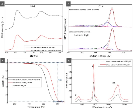
but smaller, c.a. 35 nm platelets could be also rarely observed by TEM (SI). The analysis of the interplane lattice spacing confirms the iron oxide spinel structure, fig. 3f and the iron oxide (III) phase is confirmed by XPS analysis, fig. 4a. Similarly to the previous sample, there are no significant changes in the type of oxygenated groups, fig. 4b, while much higher graphitization degree of FLG can be observed after µ-wave treatment from the clear shift of combustion temperature in TGA curve, fig.4c. The latter has also the reflection in Raman spectra: ID/IG ratio
decreases from 0.21 to 0.18, where D peak (~1347 cm-1) and G peak (~1581 cm-1) are vibration signatures of “defected” and highly graphic carbon, respectively, Fig. 4.d. Apart from hexagonal platelets the second elongated form of iron oxide NPs, sticks, can be observed, fig. SI d. Their presence could be possibly attributed to the formation at the FLG sheets’ edges, without significant interactions with graphitic terraces’ surface. Such situations could be attributed to the multi-step structure defined by us earlier for the used here FLG and the presence of short terraces [9]. It cannot be however excluded that the sticks are not also an issue of the scrolled thin platelets; their length corresponds to the lateral size of the hexagons (SI e,f).
Fig. 3. a,b) SEM micrographs and c-f) TEM micrographs of iron oxide hexagonal platelets over FLG (FLG-FexOy-2). 200 µm 60 nm 200 nm 2 n m 2,5 Å a b c d e f
7
Fig. 4. A, b) Fe2p and C1s XPS spectra of iron oxide over FLG before and after µ-waves treatment, c) and d) corresponding TGA and Raman spectra
The presented examples show that not only the flattening of metal occurs but also graphene became a template for the well-defined metal nanoplateles, especially in the case of µ-waves treated sample. While the interactions between the graphitic support and metal provide the well-structured flattened metal species, once the latter are formed and the support has high graphitization degree, the interfacial interactions become much weaker. The overall dispersion of metal over FLG surface remains however significant, which confirms additionally the existence of significant interactions between FLG and metal, before and initially during the annealing treatments. Gradually, most of the 2D NPs don’t lie on but tilt from FLG support indicating that the surface-free energy of separated FLG and NPs systems decreased. The above phenomenon could be explained by the fact that at standard conditions (before annealing/low temperature annealing) the graphitic surface is always “defected”, including the adsorbed impurities while Fe NPs have higher degree of oxidation. Due to their unsaturated and/or reactive natures, different kind of defects in the graphitic lattice (structural e.g. carbon vacancy or edges, heteroatoms e.g. oxygen, nitrogen, adsorbed species e.g. hydrocarbons) are well known stabilizing centers for metal matter whose ensure high dispersion of metal [11, 22, 23]. Since the edges of FLG with unsaturated bonds allows for covalent -bonding, pure graphitic surface commands only pz orbitals to make relatively weak bonding with the metals including
the metals with unfilled d orbitals such as Fe [22]. The interactions are however sufficient to induce the flattening of metal during the temperature increase (it was somehow suggested previously that this kind of interactions can alter the electronic modification and ligand-to-metal charge transfer can occur [2]) and keep homogenously dispersed metal over FLG surface at the end. Before however the NPs crystallize in hexagonal flattened form, several potential
D G 2D iron oxide FLG a b c d
8
phenomena such as melting or surface melting (in the first example), coalescence, splitting [18, 24-26] (regardless the carbon etching) happen. This is especially pronounced in the case of µ-waves treated sample, where extremely high temperatures at FLG surface are expected and the melting of Fe NPs, even of relatively large size occur before their crystallization over graphitic template.
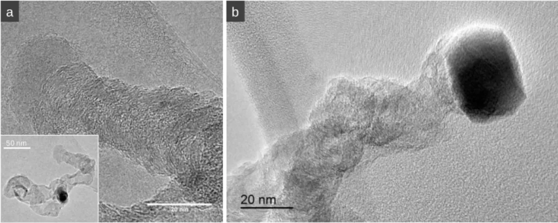
Fig. 5. TEM micrographs of CNFs growth over iron-oxide/FLG catalysts.
The Fe-based hexagonal NPs are no more chemically attached to the graphene surface, but demonstrate significant attractive (or the balance between attractive and repulsive) interactions with the support surface thereby ensuring homogenous distribution of the crystals. The titling of the Fe-based NPs from the FLG surface is an important advantage since not only one but two flat surfaces of NPs are accessible for their future potential applications. The weak interactions between Fe-based NPs and FLG are also indirectly confirmed through the results obtained from the CVD synthesis of carbon nanofibers (CNF) on the FexOy-FLG-1 sample. Fig. 5 shows the
TEM micrographs of the synthesized CNFs. As can be seen from Fig.5.a, the tip-growth type of CNFs is observed, i.e. Fe-based catalyst NPs lift with grown fibers. This type of growth is attributed to the weak interactions between catalyst NPs and the support. It seems in addition that both flat surface of the catalyst are active, since the growth of CNF can be observed from both sides of the NPs as well (Fig. 5.b).The growth of such morphology CNFs, i.e. in which graphitic planes are perpendicular to the longitudinal axe of fibers confirm flattened morphology of NP catalyst and its sharp edges [16]. The graphitic planes are indeed formed parallel to the catalyst surface [27, 28]. The sharp edged polygonal catalyst NPs are also observed after CNFs grown on the CNFs graphitic surface, the potential reconstruction of the catalysts depends as well on the CNFs morphology (in analogical way to the FLG support) [29]. Worthy to underline is also the fact that for the “traditional” catalytic supports such as alumina or silica, the iron NPs catalyzes most often the growth of nanotubes and not nanofibers. To note is the fact that the homogenous dispersion of CNFs over FLG confirmed that no loss and/or agglomeration of FexOy-FLG-1 happened during the catalytic growth. Likewise, in view
of the catalytic application of the herein systems in a liquid phase the sonication and centrifugation of FexOy-FLG-2 in ammonia and after in ethanol have been performed. No
visible leaching/separation of FexOy from FLG was observed by TEM analysis.
50 nm
9
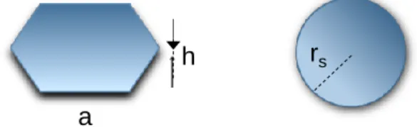
The use of FLG permits the preparation of flat particles and even if the notion of surface-to-volume is commonly known and instinctively high for the flat species vs. spherical ones for instance, no concrete comparative examples are reported. In this regard we present below some simple estimation on how the surface changes moving from sphere to hexagonal platelets keeping the same volume, and focusing on the platelets dimensions obtained in this work, i.e. hexagonal platelets of diameter (2a) of 60 nm and height (h) of 6 nm (fig. 6). The calculations, since they concern the same chemical element, are based purely on the mathematical geometrical factors without considering the crystallographic atomic arrangement.
Fig. 6. Schema of hexagonal platelet vs. spherical particle Surface of regular hexagon with side a is: 𝑆ℎ = 3𝑎2√3
2
Total surface of hexagonal plates with side a and high h (TSA) is: 𝑇𝑆𝐴 = 2 × 𝑆 𝑥 6(𝑎 × ℎ)
If we estimate that volume of hexagonal plate is equal to volume of sphere (the same number of volumetric atoms): 𝑉ℎ = 𝑉𝑠 3ℎ𝑎2 √3 2 = 4 3𝜋𝑟𝑠 3 , so: 𝑟𝑠 = √3ℎ𝑎 2√3 × 3 2 × 4𝜋 3 The rs ≈ 15 nm (a=30 nm, h= 6 nm)
We can calculate the surface of sphere corresponding to this Vs:
𝑆𝑠 = 4𝜋𝑟𝑠2
The ratio between TSA and Ss for a hexagonal plate with 2a=60 nm and aspect ratio (2a/h) of
10 (h=6 nm), and the sphere with r ≈ 15 nm is around 2. 𝑘 = 𝑇𝑆𝐴 𝑆⁄ 𝑠 ≈ 2
a
10
The gain in surface area is twice, while the sphere with the same volume of atoms than hexagonal plate of 60 nm would have 30 nm of diameter. The k would increase of course in non-linear manner with the increase of aspect ratio of the hexagonal plate: e.g.: the k ≈ 5.7 for 2a/h = 60, k ≈ 7.9 for 2a/h = 100, and k ≈ 91 for 2a/h=476, the h = 0.126 nm equivalent to hypothetical monoatomic Fe layer. The latter one, the monoatomic hexagonal plate would correspond to sphere of 4 nm.
To satiate the curiosity, we have also calculated what size of Fe monoatomic hexagonal plate would correspond to a sphere of 60 nm in diameter; such platelets would be of 1.167 m size. Conclusion
We show that due to its 2D nature, FLG can be used as a template for the synthesis of flat metal NPs, i.e. with enhanced surface-to-volume ratio. Despite a high temperature applied for the preparation of flat NPs (annealing conditions) and certain coalescence, the overall dispersion of the metal remains high; while the surface-to-volume ratio of NPs is kept in some extend due to the flat NPs’ structure. The stability of well dispersed Fe NPs at such high temperature provides an important advantage for different applications such as catalysis. The work is undergoing in order to obtain and control optimally thin NPs mainly for catalytic applications.
Author contributions: A. Mohanty and M. Lafjah: most of the experiments and analysis, W. Baaziz: synthesis of FLG-FexOy-1 and TEM microscopy and analysis, V. Da Costa: AFM microscopy, I. Janowska: principal investigator/ project coordinator, writing, calculations, selected experiments.
Acknowledgments
FRC-Solvay foundation is greatly acknowledged for A. Mohanty’s PhD fellowship support. References
1. Y. Liang, Y. Li, H. Wang, J. Zhou, J. Wang, T. Regier, H. Dai, Co3O4 nanocrystals on graphene as a synergistic catalyst for oxygen reduction reaction. Nature Materials 10 (2011) 780.
2. L. Truong-Phuoc, C. Pham-Huu, V. Da Costa, I. Janowska, Few-layered graphene-supported palladium as a highly efficient catalyst in oxygen reduction reaction. Chemical Communications 50 (2014) 14433-14435.
3. C. Zhang, R. Hao, H. Yin, F. Liu, Y. Hou, Iron phthalocyanine and nitrogen-doped graphene composite as a novel non-precious catalyst for the oxygen reduction reaction. Nanoscale 4 (2012) 7326-7329.
4. A. R. Harutyunyan, G. Chen, T. M. Paronyan, E. M. Pigos, O. A. Kuznetsov, K. Hewaparakrama, S. M. Kim, D. Zakharov, E. A. Stach, G. U. Sumanasekera, Preferential Growth of Single-Walled Carbon Nanotubes with Metallic Conductivity. Science 326 (2009) 116.
5. Y. Yang, S. Matsubara, L. Xiong, T. Hayakawa, M. Nogami, Solvothermal Synthesis of Multiple Shapes of Silver Nanoparticles and Their SERS Properties. The Journal of Physical Chemistry C 111 (2007) 9095-9104.
11
6. W. Mengting, T. Yanase, F. Uehara, S. Watanabe, T. Miura, T. Nagahama, T. Shimada, Switching of the products by changing the size and shape of catalytic nanoparticles during CVD growth of MoS2 nanotubes. CrystEngComm 19 (2017) 3915-3920.
7. N. Niklas, M. Sterrer, S. Shaikhudinov, D. Menzel, H. J. Freund, Model Systems in Catalysis for Energy Economie, in: R. Schlögl (Ed.), Chemical Energy Storage. Walter de Gruyter GmbH, Berlin/Boston (2012) 329-352.
8. A. A. Pirzado, L. Truong-Phuoc, V. Papaefthimiou, C. Matei Ghimbeu, F. Le Normand, H. Ba, T. Thanh-Tung, C. Pham-Huu, I. Janowska, Activation of few layer graphene by μW-assisted oxidation in water via formation of nanoballs – Support for platinum nanoparticles. Journal of Colloid and Interface Science 451 (2015) 221-230.
9. M. S. Moldovan, H. Bulou, Y. J. Dappe, I. Janowska, D. Bégin, C. Pham-Huu, O. Ersen, On the Evolution of Pt Nanoparticles on Few-Layer Graphene Supports in the High-Temperature Range. The Journal of Physical Chemistry C 116 (2012) 9274-9282.
10. Q. Yuan, Z. Xu, B. I. Yakobson, F. Ding, Efficient Defect Healing in Catalytic Carbon Nanotube Growth. Physical Review Letters 108 (2012) 245505.
11. F. Banhart, J. Kotakoski, A. V. Krasheninnikov, Structural Defects in Graphene. ACS Nano 5 (2011) 26-41.
12. B. F. Machado, P. Serp, Graphene-based materials for catalysis. Catalysis Science & Technology 2 (2012) 54-75.
13. J. Zhu, A. Holmen, D. Chen, Carbon Nanomaterials in Catalysis: Proton Affinity, Chemical and Electronic Properties, and their Catalytic Consequences. ChemCatChem 5 (2013) 378-401.
14. W. Baaziz, L. Truong-Phuoc, C. Duong-Viet, G. Melinte, I. Janowska, V. Papaefthimiou, O. Ersen, S. Zafeiratos, D. Begin, S. Begin-Colin, C. Pham-Huu, Few layer graphene decorated with homogeneous magnetic Fe3O4 nanoparticles with tunable covering
densities. Journal of Materials Chemistry A 2 (2014) 2690-2700.
15. I. Janowska, F. Vigneron, D. Bégin, O. Ersen, P. Bernhardt, T. Romero, M. J. Ledoux, C. Pham-Huu, Mechanical thinning to make few-layer graphene from pencil lead. Carbon 50 (2012) 3106-3110.
16. S. S. Datta, D. R. Strachan, S. M. Khamis, A. T. C. Johnson, Crystallographic Etching of Few-Layer Graphene. Nano Letters 8 (2008) 1912-1915.
17. I. Janowska, M.-S. Moldovan, O. Ersen, H. Bulou, K. Chizari, M. J. Ledoux, C. Pham-Huu, High temperature stability of platinum nanoparticles on few-layer graphene investigated by In Situ high resolution transmission electron microscopy. Nano Research 4 (2011) 511-521. 18. W. Baaziz, G. Melinte, O. Ersen, C. Pham-Huu, I. Janowska, Effect of nitriding/nanostructuration of few layer graphene supported iron-based particles; catalyst in graphene etching and carbon nanofilament growth. Physical Chemistry Chemical Physics 16 (2014) 15988-15993.
19. Y. Hou, Z. Xu, S. Sun, Controlled Synthesis and Chemical Conversions of FeO Nanoparticles. Angewandte Chemie International Edition 46 (2007) 6329-6332.
20. M. Jean-Baptiste, From epitaxial growth of ferrite thin films to spin-polarized tunnelling. Journal of Physics D: Applied Physics 46 (2013) 143001.
21. J. A. Menéndez, A. Arenillas, B. Fidalgo, Y. Fernández, L. Zubizarreta, E. G. Calvo, J. M. Bermúdez, Microwave heating processes involving carbon materials. Fuel Processing Technology 91 (2010) 1-8.
22. F. Banhart. Interactions between metals and carbon nanotubes: at the interface between old and new materials. Nanoscale 1 (2009) 201-213.
23. D. S. Su, S. Perathoner, G. Centi. Nanocarbons for the Development of Advanced Catalysts. Chem. Rev. 113 (2012) 5782-5816.
12
24. F. Schäffel, J. H. Warner, A. Bachmatiuk, B. Rellinghaus, B. Büchner, L. Schultz, M. H. Rümmeli, Shedding light on the crystallographic etching of multi-layer graphene at the atomic scale. Nano Research 2 (2009) 695-705.
25. C. W. Keep, S. Terry, M. Wells, Studies of the nickel-catalyzed hydrogenation of graphite. Journal of Catalysis 66 (1980) 451-462.
26. K.-H. Kim, A. Gohier, J. E. Bourée, M. Châtelet, C.-S. Cojocaru, The role of catalytic nanoparticle pretreatment on the growth of vertically aligned carbon nanotubes by hot-filament chemical vapor deposition. Thin Solid Films 575 (2015) 84-91.
27. I. Martin-Gullon, J. Vera, J. A. Conesa, J. L. González, C. Merino, Differences between carbon nanofibers produced using Fe and Ni catalysts in a floating catalyst reactor. Carbon 44 (2006) 1572-1580.
28. A. Rinaldi, J.-P. Tessonnier, M. E. Schuster, R. Blume, F. Girgsdies, Q. Zhang, T. Jacob, S. B. Abd Hamid, D. S. Su, R. Schlögl, Dissolved Carbon Controls the Initial Stages of Nanocarbon Growth. Angewandte Chemie International Edition 50 (2011) 3313-3317.
29. X. Duan, G. Qian, X. Zhou, Z. Sui, D. Chen, W. Yuan, Tuning the size and shape of Fe nanoparticles on carbon nanofibers for catalytic ammonia decomposition. Applied Catalysis B: Environmental 101 (2011) 189-196.