Integrated methods and scenario development for urban groundwater
management and protection during tunnel road construction: a case
study of urban hydrogeology in the city of Basel, Switzerland
J. Epting&P. Huggenberger&M. Rauber
Abstract In the northwestern area of Basel, Switzerland, a tunnel highway connects the French highway A35 (Mulhouse–Basel) with the Swiss A2 (Basel–Gotthard– Milano). The subsurface highway construction was asso-ciated with significant impacts on the urban groundwater system. Parts of this area were formerly contaminated by industrial wastes, and groundwater resources are exten-sively used by industry. During some construction phases, considerable groundwater drawdown was necessary, lead-ing to major changes in the groundwater flow regime. Sufficient groundwater supply for industrial users and possible groundwater pollution due to interactions with contaminated areas had to be taken into account. A groundwater management system is presented, comprising extensive groundwater monitoring, high-resolution numer-ical groundwater modeling, and the development and evaluation of different scenarios. This integrated approach facilitated the evaluation of the sum of impacts, and their interaction in time and space with changing hydrological boundary conditions. For all project phases, changes of the groundwater system had to be evaluated in terms of the various goals and requirements. Although the results of this study are case-specific, the overall conceptual approach and methodologies applied may be directly transferred to other urban areas.
Résumé Au nord-ouest de Bâle, en Suisse, un tunnel-autoroutier connecte l’autoroute française A35 (Mulhouse-Bâle) avec l’autoroute suisse A2 (Bâle-Gotthard-Milan). La construction de la chaussée a été associée à des impacts significatifs sur le système urbain d’eau souterraine. Des parties de la zone avaient été auparavant contaminées par des déchets industriels, et les ressources en eau souterraine sont intensivement utilisées par l’industrie. Durant certaines phases de la construction, un rabattement très important a été nécessaire, conduisant à des change-ments importants du régime d’écoulement de l’eau souter-raine. Une alimentation suffisante en eau souterraine pour les industriels et une pollution possible de l’eau souterraine du fait d’interactions avec des zones contaminées ont du être pris en compte.Un système de gestion de l’eau souterraine est présenté, comprenant un système étendu de surveillance de l’eau souterraine, un modèle hydro-géologique de haute résolution, et le développement et l’évaluation de différents scénarios. Cette approche inté-grée a aidé à évaluer l’ensemble des impacts, et leur interaction dans le temps et l’espace avec les variations des conditions hydrologiques aux limites. Pour toutes les phases du projet, les changements du système eau souterraine ont du être évalués, au regard des divers buts et nécessités. Bien que les résultats de cette étude sont spécifiques à ce projet, l’approche conceptuelle globale et les méthodes appliquées pourraient être transférées directe-ment à d’autres zones urbaines.
Resumen En el área del noroeste de Basilea, Suiza, un túnel de carretera conecta la carretera francesa A35 (Mulhouse–Basilea) con la A2 suiza (Basilea–Gotthard– Milano). La construcción subsuperficial de la carretera estuvo ligada con impactos significativos sobre el sistema de agua subterránea urbano. Algunas partes de esta área fueron contaminadas anteriormente por desechos industri-ales, y los recursos de agua subterránea son usados ampliamente por la industria. Durante algunas fases de la construcción fue necesario crear abatimientos consider-ables del agua subterránea, generando cambios mayores en el régimen delflujo del agua subterránea. Debieron ser tenidos en cuenta tanto un abastecimiento suficiente con agua subterránea para los usuarios industriales, como también la posible contaminación del agua subterránea debido a las interacciones con las áreas contaminadas. Se presenta un sistema de gestión de agua subterránea, Received: 24 November 2006 / Accepted: 2 November 2007
Published online: 19 December 2007 *Springer-Verlag 2007
J. Epting ())
:
P. HuggenbergerApplied and Environmental Geology Group,
Department of Environmental Science, University of Basel, Bernoullistrasse 38, 4056 Basel, Switzerland
e-mail: [email protected] Tel.: +41-61-2673446
Fax: +41-61-2672998 M. Rauber
Ernst Basler + Partner AG,
Zollikerstrasse 65, 8702 Zollikon, Switzerland e-mail: [email protected]
incluyendo un monitoreo extenso de esta misma, mod-elamiento numérico de resolución alta para el agua subterránea, y el desarrollo y evaluación de escenarios diferentes. Este acercamiento integrado facilitó la eval-uación del total de impactos, y de su interacción en el tiempo y espacio con las condiciones cambiantes en los límites hidrológicos. Para todas las fases del proyecto, los cambios del sistema del agua subterránea tuvieron que ser evaluados en términos de las metas y requisitos variados. Aunque los resultados de este estudio son específicos del caso, pueden transferirse directamente a otras áreas urbanas, tanto el acercamiento conceptual global, como las metodologías aplicadas.
Keywords Urban groundwater .
Groundwater management . Groundwater protection . Subsurface infrastructure development . Switzerland
Introduction
Groundwater in urban areas is under increasing pressure. According to the European Environmental Agency, about 70% of the European population lives in urban areas, which cover in total about 25% of the total territory (EEA 1999). With over 40% of the water supply of Western and Eastern Europe and the Mediterranean region coming from urban aquifers, efficient and cost-effective manage-ment tools for this resource are essential to maintain the quality of life and ensure that water is available for use by future generations (Eiswirth et al. 2003, 2004). Sustain-able use of soil and groundwater resources and protection and conservation of their quality are hence a key issue of European environmental policy and an enormous challenge for European research (Prokop2003).
As a result, in recent years, urban hydrogeology has emerged as a specialized area of research. While the basics of groundwater as a science are well established, the specific aspects of groundwater in urban environments have only recently been recognized (Vázquez-Suñé et al. 2005). This resulted in the foundation of the Commission on Groundwater in Urban Areas in 1993 by the International Association of Hydrogeologists (IAH), as well as initiation of projects like AISUWRS (Assessing and Improving Sustainability of Urban Water Resources and Systems; Eiswirth et al. 2003; Wolf et al. 2006) and NeWater (New Methods for Adaptive Water Management under Uncertainty; Pahl-Wostl et al. 2005). In addition, the number of international congresses and workshops (Chilton et al. 1997; Ellis 1999; SGH 2006) and the number of publications and books on urban groundwater and its sustainable use continuously increase (e.g. Lerner 1996,2003; Eyles1997; Gossell et al.1999; Aldrick et al. 1999; Foster 2001; Eiswirth 2001; Howard and Israfilov 2002; Vázquez-Suñé et al.2005; Howard2006).
The challenge to develop and implement integrated and adaptive water management requires innovative approaches that take into account the full complexity of the systems to be managed (Pahl-Wostl2006). The basic
principles of these approaches, including groundwater monitoring and modeling, are already established (Eiswirth et al. 2003; Fatta et al. 2002; Pahl-Wostl et al. 2005). However, their application in urban planning processes has rarely been accomplished.
The purpose of this report is to discuss strategies and to understand and predict the cumulative effects of the numerous single impacts to groundwater resources during a major suburban development project at the regional scale of the city of Basel (Fig. 1). Often, infrastructure development and associated alterations in land use only consider the benefits for the improved infrastructure itself and planning largely takes the pragmatic form of engineering for short-term economic objectives. This often leads to adverse effects on groundwater flow regimes with respect to quantity and quality of water resources. The term “groundwater flow regime” thereby includes all groundwater flow patterns, velocities and budgets for a defined region in a temporal context. To develop concepts and methods for sustainable groundwa-ter use in urban areas, environmental impact assessments not only have to include above-ground impairments such as ground motions with effects on existing buildings and infrastructures, as well as noise exposure and air pollution, but also the negative impacts on groundwater flow regimes.
This study illustrates selected examples, focusing on a construction phase that is associated with considerable changes to the groundwater flow regime resulting in the turnaround offlow lines and shift of groundwater divides.
Settings
Geography and hydrogeology
Basel, located in northwestern Switzerland, borders both Germany and France. The River Rhine enters Basel from the east and changes its course towards a northern direction within the city (Fig. 1). The highway construc-tion secconstruc-tions outlined in this report are located in the northwestern part of Basel to the west of the Rhine. The shallow unconfined aquifer mainly consists of late Pleistocene gravel deposited by the Rhine. The gravel deposits, interbedded with fine-grained, flood plain sedi-ments result in variable hydraulic conductivity within the aquifer. The thickness of the aquifer, ranging between 15 and 35 m, is underlain by an aquiclude composed of Oligocene mud to clay rich sediments. The general slope and the main directions of the regional groundwaterflow are S–N and E–W. Ancient abandoned channels cut into the pre-Quaternary bedrock surface and result in the steep slope of the aquiclude topography (Fig.2; Table1).
Figure 3 shows three examples of hydrographs that characterize the regional hydrological settings. The hydro-graph of observation well 1305 (Fig. 3a) illustrates the regional trend of the groundwater flow regime. This hydrograph is not influenced by groundwater use and shows a slow response to recharge from precipitation. By contrast, water-levelfluctuations in observation well 1893
(Fig. 3b) show periodic water-level changes related to nearby industrial groundwater use while the water-level fluctuations in observation well 1041 (Fig.3c) next to the Rhine correspond to the river-level fluctuations. This demonstrates that river–groundwater interactions along the Rhine are an important element of the regional groundwater-flow regime. The water-table fluctuations are phase-delayed and have reduced amplitude in response to the river-level fluctuations. Depending on hydrologic constraints, the river acts both as a receiving (“gaining”) and an infiltrating (“losing”) stream. Seasonal river-head fluctuations are moderate, as well as those observed in the observation wells close to the river, and are in the order of 1 m.
The long-term average for yearly precipitation is 788 mm, measured during the 30-year period 1961–1990 at the Binningen meteorological station (Fig. 1). Urban-ization has led to an increase in impermeable surfaces, thereby causing a reduction in direct groundwater recharge and generation of additional surface runoff from precipitation. As a result, a large spatial and temporal variability in recharge rates over short distances can be observed. For the region of Basel, current studies indicate that natural monthly groundwater recharge from precipi-tation range from 5 to 45 mm for non-sealed surfaces and
from 2 to 25 mm for areas with a high degree of surface sealing (Huggenberger et al. 2006).
At the beginning of the 1900s, to stabilize the river bank for harbor facilities, a sheet pile wall, approximately 500 m long and 20 m deep, was driven down to the bottom of the aquifer on the western river bank north of the main course of the tunnel road (Fig. 1). It acts as a low-permeability barrier and reduces locally the interac-tion between river and groundwater. Regionally, it forces the groundwater toflow either south or north of this wall, thereby creating an area of low-flow velocity near the sheet pile wall, and an E–W groundwater divide running behind the wall. Since the position of this groundwater divide shifted during the different construction phases, it provides a key indicator for changes in the northern groundwaterflow regime.
Urban infrastructure development
Open space in urban areas is very rare and new infrastructure is increasingly constructed in the subsurface under difficult geotechnical and hydrogeological condi-tions (other examples include: “Big Dig”, a major highway in Boston, USA (Altshuler and Luberoff 2003); and infrastructure constructions in central Berlin, Ger-Fig. 1 Investigation area in Basel—northwestern Switzerland, bordering France (F) and Germany (G). Note that the highway tunnel runs at an angle of approximately 60° (counterclockwise) to the regional groundwaterflow. In the middle of the right-hand column, the years are given within which each section of the construction was completed
many (Hufschmied 2006). In particular, tunnel construc-tion in nonconsolidated rocks and below the water table can lead to a higher risk of subsidence. To maintain city life and safety standards on the construction site, geotechnical measures such as cement injections for subsurface stabilization are commonly used.
Subsurface constructions can result in significant changes in groundwater quality and dynamics of both local and regional groundwaterflow regimes. While some changes only temporarily affect urban groundwater sys-tems during construction others are permanent, like the reduction of cross-sectional groundwaterflow and aquifer-storage capacities. Together with various sources of groundwater pollution observed in urban environments, subsurface construction may interfere with a previously balanced urban-groundwaterflow regime.
The subsurface highway construction highlighted in this report is 3.2 km long and connects the French highway A35 (Mulhouse–Basel) with the Swiss A2 (Basel–Gotthard–Milano). It is divided into four sections, of which about 87% are tunnel constructions; the remaining 13% consist of the bridge across the Rhine and the various tunnel entrances (Fig.1).
The overall route planning and final decision for the realization of the tunnel highway connection was com-pleted some 30 years ago. Therefore, it was not possible to conduct investigation studies comparing various courses for the realization of the tunnel and to evaluate solutions with minimal impact to the groundwaterflow regime. At that time, studies only concentrated on potential mitigation of various impacts. The term “mitigation” encompasses a broad range of measures that might reduce or compensate the effects of environmental damage (National Research Council1992).
Construction started in 1994 and the whole highway project will be completed by the end of 2008 (Fig.1). The progressive shift of the construction sites, requiring different drainage systems, affected the groundwaterflow regime throughout construction. Depending on the exca-vation technique applied, complexity of the groundwater drainage varied and was realized either as open sump drainage, the dewatering of residual groundwater in areas enclosed, or a combination of both methods (Fig.4). Open sump drainages are generally associated with major Fig. 2 Bedrock surface and boundary conditions used for the
numerical groundwater model. Groundwater budgets were calculat-ed across all model boundaries. Additionally, groundwater budgets for zone 1 and the inflow budgets, from different directions (symbolized by the pie diagram), to the drained construction site were evaluated (Table1). The industrial subregion, called zone 1, is characteristic for the totalflow rate through the northern industrial area
Table 1 Total rates (in l s−1) of extraction and injection as well as water budgets (in l s−1) across model boundaries, zone 1 and the inflow budgets, from different directions, to the drained construction (see Fig.1for locations of wells and Fig.2for locations of zones for water budgets)
Wells Inflow budgets to the construction site
Model boundaries Zone 1
Extraction Recharge East South West North South West R. Rhine
In Out In Out A Situation March 2003 70.3 3.5 6.3 13.2 9.4 14.4 105.1 Noflow No flow 3.5 65.5 12.8 B Situation February 2006 (maximum drawdown) 142.8 46.9 29.9 35.9 43.3 6.9 77.5 52 51.6 11.2 25.4 4.1 C Scenario February 2006 (without injection) 123.8 1.6 27.2 33.5 30.6 5.8 77.1 40.7 62.8 10.4 28 2.4
D Future state 48.3 3.5 9.6 10.3 6.6 13.5 104.9 Noflow No flow 3.1 75.7 9.5 Flows are considered“in” if they are entering a subregion
changes in groundwaterflow regimes. By contrast, for the dewatering of residual groundwater in areas enclosed, additional technical measures have to be employed (cement injections for subsurface stabilization, sheet pile walls and slide pales). They will, after completion of the construction works, irreversibly degrade the aquifer. During the construction of the highway access and exit roads to the main tunnel, called “Tunnel Luzernerring” (Figs. 1, 2, 4, 5 and 6), a combination of both drainage systems with groundwater extractions up to approximately
140 l s−1 (October 2003 to May 2007) was chosen. The exit road crosses below the main tunnel road and is thus the deepest part of the entire construction requiring maximum drawdown. Once the construction is completed, connectivity of the groundwater will be enhanced by technical measures such as the installation of highly permeable culverts as well as drawing sheet pile walls and slide pales.
Industrial groundwater use
In the investigation area, groundwater resources are exten-sively used by industry for processing or cooling (Fig.1). A total of 13 industrial wells are operated in the vicinity of the construction site. The average amount of groundwater extracted from the aquifer is about 30 l s−1, and approximately 3.5 l s−1are injected back into the aquifer.
The significant drawdown during single construction phases on the one hand and the injection of groundwater with potentially elevated temperatures on the other hand could lead to supply shortages. In this case, the construction site owner would be responsible for an alternative supply, leading to a significant financial burden. Therefore, it is advisable to develop alternative supply strategies for processing water in advance. For this purpose, negotiations with all relevant users were conducted to determine the individual quantitative and qualitative requirements. Users of groundwater for cooling purposes could be supplied by lower quality groundwater from the construction site. Nevertheless, temperature limits must be observed.
Contaminated areas
Since Basel turned into a major industrial centre for the chemical and pharmaceutical industry in the nineteenth century, vast areas have been or are likely to be contaminated (Fig.1). Contaminants mainly include residues and solvents from the color industry, like BTEX/MTBE (benzene, toluene, ethylbenzene, xylenes/methyl tertiary butyl ether), volatile organic compounds, chlorinated compounds and their metabolites, as well as metals. In addition, other abandoned sites of small enterprises and numerous con-taminated areas on adjacent French territory lie close to the construction site. As environmental problems generally do not stop at national boundaries, this obviously requires conceptual and cross-national investigations of the ground-water system.
Changes in the groundwater flow regime caused by groundwater drawdown during individual construction phases may lead to a reversal offlow lines and can induce serious water-quality deterioration (Foster 2001). As a result, contaminated areas may suddenly lie in the capture zones of the industrial groundwater users or within the groundwater drainage area of the construction site.
Legal framework
Although legal frameworks for groundwater protection as well as groundwater policy strategies have continuously Fig. 3 Examples of hydrographs that characterize the regional
hydrological settings for the year 2005: a well 1305, b well 1893, c well 1041 (see Fig.1for locations of observation wells)
been adjusted in the last decades (e.g. quantitative conservation of groundwater resources, Art. 43, last revision of the GSchG (1991); approval of subsurface constructions, Art. 32, last revision of the GSchV (1998), drainage of subsurface constructions, Art. 44, last revision of the GSchV (1998)), considerable damage to ground-water flow regimes still occurs. There are several reasons for this. Firstly, more attention is paid to purely techno-logical and constructional problems concerning ground-water management during construction rather than to issues dealing with sustainable groundwater use or possible interferences with historically polluted industrial areas. Secondly, some projects undertaken under outdated
legal frameworks, i.e. some 30 years ago, would not be approved today because more restrictive laws pertaining to groundwater, as well as changed perceptions and policy concerning groundwater and its sustainable use, now apply. Thirdly, groundwater protection in urban areas is still focused mainly towards documentation of changes in groundwater quality and the groundwaterflow regime like maintaining local flow capacities and preventing a significant lowering of the water table. Less attention is paid to the prediction of future demands and to the management of groundwater resources. Fourthly, until now, the impacts of various groundwater users were only regarded as solitary limited impacts and examinations of Fig. 4 Illustration of different drainage systems employed. Cross section A–A′: dewatering of residual groundwater in areas enclosed; cross section B–B′: open sump drainage
the interactions between them and other aspects such as possible interactions with former industrial sites, were not attempted.
Therefore, the maintenance of a relevant specific ground-water flow regime together with new legislation frame-works, handling pollution of historically industrial areas, must be seen in a broader context. Under present regulations, any disturbance of the ordinary groundwater flow regime, including changes offlow direction and potential mobiliza-tion of contaminants, would have consequences with respect to responsibilities of the parties involved. This would include financing evaluations and implementations of remedial measures. Furthermore, additional contracts be-tween the city of Basel and individual groundwater users assure the latter of an agreed amount of groundwater extraction. Likewise, in case of supply shortages caused by the drainage on the construction site, the party responsible for disturbing the initial status would have to come up with alternative supply solutions.
Conceptual approach and methodology
In the following sections, the conceptual approach and the methodology of this study, consisting of the various elements of the groundwater management system, are described.
Conceptual approach
Primarily, the area of investigation was delineated encom-passing an inventory of all relevant boundaries character-izing the regional groundwater flow regime as well as all possible impacts to it before the beginning of the construction (Fig.7). In the next step, the hydrogeological boundary conditions and impacts were identified that may be subject to changes during the tunnel construction.
Within these defined boundaries, goals for a sustain-able development are formulated. These goals guide mitigation strategies and refer to defined standards, i.e. natural composition of groundwater or quality standards
defined by existing regulations. They also establish a standard against which individual decisions are made. Goals with respect to the groundwaterflow regime at the regional scale should be based on knowledge of the physical properties governing the system. The general goals at the regional scale are: (1) minimization of changes of the groundwater flow regime, including the maintenance of the courses of regional and local ground-water divides, dimensions of groundground-water budgets, and groundwater flow velocities; (2) consideration of addi-tional future groundwater use; and (3) long-term improve-ment of groundwater quality, with main focus on former industrial sites. At the local scale, in the vicinity of the construction site, goals should focus on: (1) minimization of backwater effects behind parts of the construction extending below the water table; and (2) prevention of the development of stagnating groundwater zones close to construction elements, extending below the water table. These elements can act as a barrier to groundwater flow and would reduce the storage volume of the aquifer.
In order to attain these goals, a definition of profiles is required that describe the groundwater system before, during and after the completion of the construction works. These profiles include an inventory of the hydrogeological boundary conditions and the multiple impacts on the groundwaterflow regime at specified times. Based on this information, it is possible to identify and to describe an initial profile of the system, as well as to define desirable profiles for the individual construction phases and for the status after the completion of the tunnel road. The concluding profile comprises the general goals for the future development of the groundwater flow regime and groundwater quality. Some impacts will only tempo-rarily affect the system during the construction of the tunnel road, like groundwater extractions and injection on the construction site as well as drawable sheet pile walls and slide pales. Other impacts will be permanent, like parts of the tunnel construction extending below the water Fig. 5 Tunnel-gate shaft (see Fig. 4, section A–A′). The shaft
reaches down to the bedrock
Fig. 6 From the tunnel-gate shaft the highway access and exit roads to the main tunnel are excavated using the “micro pale” mining technique
table, permanent sheet pile walls, pales and cement injections for subsurface stabilization. Permanent impacts will change aquifer properties in a virtually irreversible way leading to an altered profile of the initial system. The profiles should allow decision makers to see past and present modification patterns of the aquifer system.
In order to achieve the system profiles desired, methods have to be developed together with the definition of specific targets (Fig. 7). Whereas goals focus on a sustainable development for specific groundwater areas and a desired long-term development of urban groundwa-ter resources afgroundwa-ter project completion, targets also comprise groundwater protection issues during the development of the individual construction sections.
Targets within the previously delineated boundaries had to be defined at relevant scales and include, at the regional scale, firstly, minimization of changes to the groundwaterflow regime during construction phases. This includes the maintenance of (1) the courses of regional and local groundwater divides, (2) the course and width of capture zones of the drainage on the construction site and of the industrial groundwater users, (3) the dimensions of groundwater budgets and (4) groundwater flow lines and velocities. Other targets also included are assured supply of groundwater (quantity and quality) for industrial users; and safeguarding groundwater-quality issues during tunnel
construction. Targets at the local scale include: (1) technical solutions guaranteeing predefined lowered water tables during single project phases, including the adher-ence to safety standards on the construction site; (2) the minimization of groundwater inflow to the construction site drainages from contaminated or probably contaminated areas; (3) the documentation of contaminant mobilizations and groundwater velocities in areas that are contaminated; and (4) the minimization of backwater effects behind parts of the construction extending below the water table and the prevention of the development of stagnating groundwater in this area.
As the individual targets may interfere with each other and, together, may not necessarily lead to a desired overall goal, techniques that facilitate the comparison of interfer-ences had to be applied. This was accomplished by the development of scenarios and the implementation of equivalence and acceptance criteria (Fig. 8, Bedford 1996). They assess the technical benefits of the different engineering projects, the supply situation for industrial groundwater users, the development of the groundwater flow regime and the improvement of overall groundwater quality.
Given the multitude of anthropogenic processes occur-ring in urban areas, it is difficult or even impossible to make comparative studies with system profiles describing Fig. 7 Conceptual approach
a potentially uninfluenced natural environment. Therefore, for reference, the previously defined system profile of the initial state before the beginning of the major construction phase was chosen. Comparative studies between this initial profile and the corresponding profiles of different proposals submitted for the various construction phases were carried out. Together with equivalence and accep-tance criteria, these profiles and their impact on the groundwater flow regime and groundwater quality can be compared and evaluated (Fig. 8). Equivalence and acceptance criteria include: (1) the evaluation of simulated water budgets and velocities through defined regions, local and regional, during construction and after comple-tion of the tunnel road; (2) the assurance of groundwater supply to the industrial groundwater users, during con-struction and after completion of the tunnel road; (3) the possibility for future groundwater use in the region, after completion of the tunnel road; (4) the overall development of groundwater quality, during construction of the tunnel road and (5) the technical feasibility of the engineering proposal, concerning cost and safety requirements.
Methodology
Additional to the identification of significant factors in urban hydrological cycles, methodologies to quantify and control these factors must be developed and applied (Vázquez-Suñé et al. 2005). In order to achieve this, a groundwater management system was set up with the following two main elements: (1) an extensive groundwa-ter monitoring system for groundwagroundwa-ter levels and quality; and (2) a high-resolution numerical groundwater model
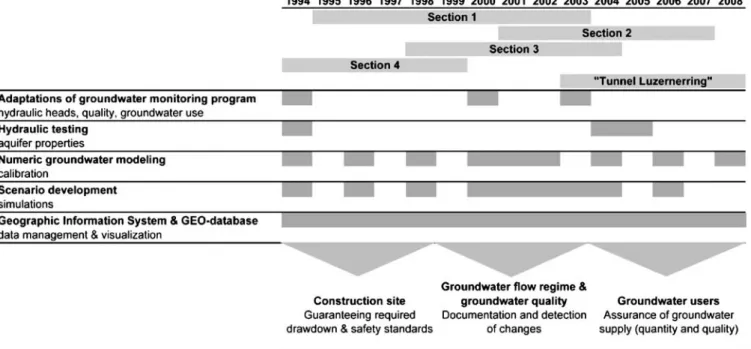
combined with scenario development. Besides a simple documentation of changes in groundwater quantity and quality, the goal of the management system is to detect undesired developments in advance. Throughout the entire progress on the various construction sections, the ground-water management system is continuously adapted and all recently obtained data (e.g. pumping test data) are incorporated (Fig.9). Data management and visualization is accomplished with a database and a geographic information system (ArcMap).
Groundwater monitoring
The network comprises 44 observation wells instrumented by automated water-level loggers for continuous measure-ment of the hydraulic head. The hydrographs of this observation network are analyzed monthly. A total of 21 observation wells are sampled regularly for groundwater-quality measurements. Seven observation wells are sam-pled quarterly and 14 half-yearly (Fig. 1). Furthermore, the extracted water for industrial groundwater use and for settling tanks on the construction sites is sampled at regular intervals. Quality measurements include, among others, physical parameters (temperature, electrical con-ductivity (EC), pH-value, oxygen content, turbidity/color and odor), organic sum parameters (dissolved organic carbon (DOC), halogenated organic compounds (AOX)), major ions, BTEX/MTBE, volatile organic compounds, chlorinated compounds and their metabolites, as well as metals.
In total, 26 extraction wells and three injection wells were installed to achieve the required drawdown of the Fig. 8 The effects expected from two different engineering proposals (A and B) during construction and after completion, employing equivalence and acceptance criteria
water table (Figs. 1and4). Wells close to each other are combined into groups and the extracted groundwater is discharged to nine settling tanks. There, the physical parameters are monitored on a daily basis. At moments of change, the pumping rates are controlled by ultrasonic flow measurement, and the discharge monitoring in the settling tanks is calibrated. Part of the extracted ground-water is injected back into the aquifer in three injection wells at distances 150−250 m from the construction site. The remaining amount of extracted groundwater is channeled to the Rhine.
In addition to long-term strategies in groundwater monitoring, short-term monitoring programs were set up during drawdown tests. These adapted programs encompass the installation of supplementary observation wells, the set up of high-frequency measurement intervals, and more detailed programs to analyze the groundwater chemistry.
The monitoring program was adapted to the progress of the various construction sections, to the current groundwater management requirements and to the results obtained from groundwater modeling. Interpretation of the changes ob-served in groundwater-quality measurements together with the modeling results allowed optimizing the localization of new observation wells. New observation wells consequently were localized (1) in the inflow of the construction site drainage and nearby groundwater users; (2) between the construction site drainage and contaminated areas; and (3) on the model boundary.
Hydraulic testing
Prior to starting the project, a series of hydraulic tests was performed. In most cases, the results could only demon-strate that the required drawdown would be achieved. Unfortunately, there was neither a documentation of the relationship of drawdown versus time nor a further analysis of aquifer parameters. Furthermore, the test results are not reproducible. Based on these tests, the values taken for hydraulic conductivity range from 1E-4 m s−1to 5E-3 m s−1.
A 14-day pumping tests was conducted in order to ensure that the required maximum drawdown for the Tunnel Luzernerring construction phase can be achieved with the number of extraction wells as predicted. As a result, the groundwater drainage for this drawdown was accomplished with 13 wells dewatering the residual groundwater in the area enclosed by sheet pile walls and with 13 wells outside the enclosed area by open sump drainage (Fig.4). Under the actual hydrological constraints, the required groundwater drawdown was achieved with a drainage rate of approxi-mately 100 l s−1. Some 50 l s−1 of the extracted groundwater was injected back into the aquifer using three injection wells. Simultaneously, eleven extraction wells of the remaining construction sites as well as nine extraction wells and one injection well of the industrial groundwater users were active.
Figure 10shows, next to cumulative rates of ground-water extraction and injection, the hydrographs of four Fig. 9 Tools employed for groundwater management during progressive construction phases
observation wells in the vicinity of the construction site. Whereas groundwater drawdown in observation wells P1 and P2 south of the construction site is distinctive, the response of the hydrograph in P3 is only small. The hydrograph in P4 clearly shows the effect of nearby groundwater injection.
The test was analyzed using the software AQTESOLV integrating transient data from multiple observation, extraction, and injection wells and considering the region as a homogeneous, anisotropic medium. For the calcula-tion of the aquifer parameters, the Neumann’s analytical solution for unsteadyflow to a partially penetrating well in an unconfined aquifer was chosen (Neumann 1974). For the specific storage value, the Moench’s analytical solution was chosen (Moench 1997). This solution assumes unsteady flow to a partially penetrating large-diameter well in an unconfined aquifer. The large-scale hydraulic conductivity resulted in an average value of 1.28E-3 m s−1. The calculation of the transmissivity of the alluvial aquifer arrived at a value of 1.67E-2 m2 s−1. Calculation of the specific yield resulted in 0.1 and of the specific storage in 7.69E-5 m−1. These additional results of aquifer parameters were used to evaluate and to validate hydraulic parameters for the groundwater model.
Groundwater modeling and scenario development Regarding selection and setup of an appropriate ground-water model, it is important to ensure that the chosen model and desired resolution are capable of answering relevant questions simultaneously. When applying groundwater models, one of the key requirements is high-quality, site-specific data (National Research Council 1990). Before setting up a groundwater model, ground-water budgets and boundary conditions—the main com-ponents of a groundwater system—must be identified and analyzed.
For groundwaterflow simulations, the three-dimensional finite difference code MODFLOW (Harbaugh et al. 2000) was employed in combination with the graphical user
interface Processing Modflow (Chiang2005). Most simu-lations were modeled steady state; the conducted pumping tests were modeled transient.
The groundwater model was continuously adapted, finally covering an area of 2,720 m ×2,860 m (about 8 km2; Fig. 1). The spatial discretisation resulted in cell sizes varying between 5 m ×5 m (near the construction site) and 30 m ×30 m in a total of 132,500 cells. An approach with four horizontal layers was chosen to vertically integrate the construction. Construction itself was integrated either as inactive cells or as horizontalflow barriers with defined hydraulic permeability. Locations with cement injections were incorporated as horizontal flow barriers (Fig. 4). During construction, progressive adjustments were made. The surface of the aquifer base (interpolated from the information of more than 400 boreholes), and the distribution of horizontal hydraulic conductivity zones (see section Hydraulic testing) was based on different type and quality data sets available from the geological database administered by the Applied and Environmental Geology Group at the University of Basel. Since the southern part of the model area has a broad steep slope in the aquifer base without any detailed geological information, hydraulic conductivity had to be calibrated. A 10:1 ratio between horizontal and vertical hydraulic conductivity was chosen. Based on a 1-day test measurement of groundwater levels (Wagner et al.2001) model boundary conditions are of the first type (fixed head) along the southern side, and of the third mixed type (leakage) along the Rhine. Hydraulic conductance of the riverbed was set at 5.0E-5 m2 s−1. The western and northern boundaries were initially specified as no flow. Pumping tests preceding the major drawdown phases indicated that this boundary is more complex. Finally, this boundary was considered as general head, leading to a groundwater outflow south of the steep slope and an inflow north of it (Fig. 2).
A total of 48 extraction wells were integrated, i.e. nine production wells and one injection well for industrial groundwater use, 35 wells extracting groundwater along the various construction sections as well as three injection wells. The hydraulic head was continuously monitored in a total of 44 observation wells. As a routine procedure, the groundwater model was calibrated at least biannually, by updating the boundary conditions and adjusting the permeability of sheet pile walls. With the calibrated groundwater model, possible scenarios were developed. Scenarios were grouped intofive types: (1) comparison of engineering projects; (2) simulation of important project phases in advance; (3) optimization of groundwater management strategies; (4) investigation of changing hydrological constraints; and (5) worst-case scenarios.
Results
The application of the conceptual approach and the methodology of the groundwater management system are illustrated by the following examples: (1) scenario develop-Fig. 10 Cumulative rates of groundwater extraction and injection
as well as hydrographs of four observation wells (P1–P4) in the vicinity of the construction site during a 14-day pumping test (see Fig.1for locations of observation and injection wells)
ment and application of equivalence and acceptance criteria; and (2) groundwater modeling results and scenario devel-opment for the construction phase requiring the maximum drawdown as well as the development of the groundwater flow regime after completion of the tunnel road.
All results are being compared with the calibrated initial state in March 2003 before the major construction phase. Furthermore, the various model calculations and developed scenarios are compared and validated by means of groundwater budgets through defined regions (Fig. 2; Table 1), the course of well capture zones as well as the description of simulated hydraulic heads, flow paths and velocities (particle tracking).
Scenario development and application of equivalence
and acceptance criteria
In the following, examples for the five scenario types are summarized (see section Groundwater modeling and scenario development).
Scenario type 1
Various engineering proposals were compared by using scenario development together with the application of equivalence and acceptance criteria. Some parts of the construction remaining below the water table after comple-tion are associated with irreversible disturbances and impede groundwater exchange. Permeability and backwater behind parts of the construction after completion was evaluated for the various proposals. This approach helped to compare different proposals with respect to feasibility and impact on the groundwaterflow regime during construction and after completion of the tunnel road.
Figure 8illustrates the procedure using the method to compare and validate two different proposals. The first engineering proposal for the Tunnel Luzernerring con-struction section suggests drainage only by dewatering of residual groundwater in the area enclosed by sheet pile walls. This proposal includes increased cement injections as well as the use of additional slide pale walls. The second proposal suggests drainage by a combination of open sump drainage and the dewatering of residual groundwater in the area enclosed (Fig. 4). For both proposals the application of culverts after completion of the tunnel road were also simulated. Additional culverts crossing under the construction, particularly required for thefirst proposal, would lead to a cost increase.
While the first proposal would influence the local groundwaterflow regime during construction but also after completion, the second one has a considerable influence on both the regional and local groundwater flow regime only during construction. The groundwater supply to industrial users in the vicinity of the construction site may be affected during construction for both engineering proposals. An appreciation of all factors gave preference to the second engineering proposal. This project had the advantage that additional measures would not be necessary. Critical sections such as Tunnel Luzernerring, where parts of the construction
almost reach down to the bedrock and the risk for subsidence during construction is the highest, were enclosed by sheet pile walls and cement injections. Outside the enclosed area, where only shallow drawdown is required, open sump drainage was employed. The combination of the two drainage methods ensured the safety standards required on the construction site. Moreover, it better fulfilled the requirements of a sustainable development of the ground-waterflow regime after completion.
Scenario type 2
Important project phases were simulated in advance. Therefore, the arrangement and required number of extraction and injection wells was evaluated for the various construction phases. The optimum arrangement of injection wells was determined resulting in a minimum change of the local groundwater flow regime in the vicinity of certain industrial groundwater users and the northern industrial area (Fig.1).
Scenario type 3
Different groundwater management strategies were com-pared. This helped evaluating the localization and operation of extraction and particularly injection wells; localization and dimension of culverts, sheet pile walls and slide pales; localization of additional observation wells; and prediction of additional groundwater use in the future.
After completion of the project, the performance of technical measures will be reviewed. Technical measures that enhance groundwater exchange beyond the construction period include the installation of culverts, sheet pile walls and slide pales. However, previous modeling suggests the effect of culverts to be rather small. The successful implementation of these measures will eventually reveal the degree to which the initial profile can be restored. Throughout the project, the results of the groundwater model allowed evaluation of the optimal localization of additional observation wells. For the prediction of additional ground-water use in the future, wells with a defined extraction rate of 20 l s−1 either north or south of the tunnel road were simulated (see the following).
Scenario type 4
Furthermore, changing hydrological constraints were investigated. Seasonal changes of groundwater recharge and levels were simulated by lifting or lowering the hydraulic head at the southern model boundary, resulting in changing inflow rates. Flood and low-water events were simulated by adjusting the water level of the River Rhine. Data for these simulations were obtained from long-time records of groundwater and river level monitoring.
Scenario type 5
Finally, worst-case scenarios were simulated. They con-centrate on incidents caused by the mobilization of
contaminants. One possible incident could occur if the drainage on the construction site drew contaminated groundwater. In case defined limits were exceeded, the extracted groundwater could not be discharged into rivers or injected back to the aquifer. Considering the worst of all cases, extracted groundwater could not even be discharged to the sewage system and would have to be pre-processed. Furthermore, for all scenarios, inaccuracies in supplied data were also taken into consideration.
Groundwater modeling and scenario development
during maximum drawdown
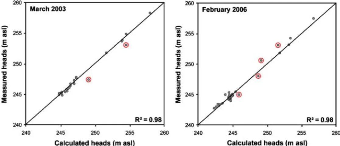
Figure 11illustrates the results from model calibrations in March 2003 and February 2006 (see also Fig.12a,b). For all model runs, divergence of calculated and observed hydraulic heads is highest for observation wells located on the broad steep slope in the southern part of the model area and is in the order of 1 m (see Figs. 1 and 2). However, the divergence for the remaining hydraulic heads averages 0.2 m.
Regional groundwater flow regime
Below, an outline of the groundwater budgets and ranges calculated across model boundaries for all scenarios are briefly summarized (Figs. 2, 12a–d and Table 1). The main model inflow occurs across the southern model boundary characterizing the natural groundwater flow regime with inflow-rates ranging between 77 and 105 l s−1. The Rhine acts both as a receiving and an infiltrating stream. Groundwater exfiltrating into the Rhine is estimated to range from 25 to 86 l s−1and infiltration ranges from 3 to 11 l s−1. Beyond the western model boundary, a groundwater outflow south of the steep bedrock slope ranging between 51 and 63 l s−1 and an inflow to the north ranging between 40 and 52 l s−1was calculated.
The calculated contour map of the hydraulic heads in March 2003 shows a main direction of the regional groundwater flow from south to north and from west to
east (Fig.12a). During this time, the extraction rates of the construction site drainages amounted to only 42 l s−1. Including industrial users, extraction rates result in a total of 70 l s−1and injection rates of about 3.5 l s−1. A steep gradient of the hydraulic heads in the middle of the model area can be observed. This coincides with the steep slope of the bedrock surface in this area (Fig.2). By contrast, a comparatively low hydraulic gradient in the northern industrial area occurs. The course of particle tracks illustrates the capture zones of the various industrial groundwater users and of the construction site drainage.
During the construction of subsurface freeway access and exit roads to Tunnel Luzernerring (see section Urban infrastructure development), maximum drawdown is re-quired with extraction rates up to 143 l s−1and injection rates of 47 l s−1(including operations of industrial users). Figure 12b shows the course of the hydraulic heads and particle tracks during the pumping test. The drawdown around the construction site is observable up to a distance of 500 m. Regions influenced are predominantly within the southern model area. As one would expect, the open-sump drainage induces a far wider-ranging drawdown compared to the dewatering of residual groundwater in the area enclosed by sheet pile walls. Extraction rates previously calculated correspond well with values mea-sured during the pumping test. The distribution and the performance of the three injection wells were confirmed. Modeling results and hydraulic heads measured show that the supply of groundwater for industrial groundwater users in the vicinity of the construction site is assured. Moreover, the change of the local groundwater flow regime of the northern industrial area is minimized. Due to the groundwater injection, the hydraulic gradient remains low in this area. Model simulations of high hydraulic heads and a flood event in the Rhine result in increased inflow rates across the southern model boundary amounting to 119 l s−1and Rhine infiltration rates of up to 133 l s−1. This results in an increase of groundwater extraction rates on the construction site of about 15 l s−1. In the northern industrial area, the western part of the groundwater divide would shift about 100 m to the south
Fig. 11 Results from model calibrations for the situation in March 2003 and February 2006 (see Fig.12a,b). Those observation wells that are located in the southern part of the model area on the broad steep slope are highlighted (see Figs.1and2)
(this scenario is not shown in Fig. 12and water budgets are not listed in Table 1).
In case contaminated groundwater reached the drainage system of the construction site, immediate action would be
necessary. If extracted groundwater exceeded concentra-tion limits, discharge into rivers or injecconcentra-tion back into the aquifer would be prohibited. In this situation, injection could not be supplemented by the remaining extraction Fig. 12 Visualization of hydraulic head distributions (0.5 m resolution) andflow paths illustrated by particle tracks (distance between two arrow heads indicates 50 day travel time) for four modeled situations: a March 2003, b February 2006, c February 2006 (without injection), and d future state. Whereas the results for a and b derive from model calibrations, those for c and d are based on simulated scenarios
wells. Figure 12c shows a simulation with a failure of groundwater injection. It is obvious that, due to the proximity of the injection wells to the construction site, before the failure some of the injected water amounting to 50 l s−1 had to be extracted again by the construction site drainage, leading to a kind of short circuit. However, the simulation results indicate that, during a failure, extraction rates on the construction site drainage could be reduced by 19 l s−1. This reduction is considerably low, compared to the previous injection of 50 l s−1. This fact reconfirmed once more that the injection mainly influences the northern part of the model area. Due to such a failure, the entire groundwater flow regime north of the steep slope would be changed. In this case, the drawdown would be observed beyond the French border. The capture zone of the drainage would widen significantly and extend from the Rhine to the western model boundary. The groundwater divide would be displaced far to the north beyond the model boundary.
The future state illustrates the situation after comple-tion of the tunnel road taking into account the final permeability in the vicinity of construction parts reaching below the water table and an additional groundwater user with extraction rates of 20 l s−1 north of the main track (Fig. 12d). The regional groundwater flow regime is comparable to that of March 2003. Furthermore, the effect of backwater along the main track is still observable. Additional groundwater use, even behind the tunnel construction, would be possible.
Local groundwater flow regimes
Changes in the local groundwater flow regimes are documented by means of calculated groundwater budgets and groundwater flow velocities for selected areas. The subregion, called zone 1, is characteristic for the totalflow rate through the northern industrial area. In addition, the inflow budgets from different directions to the drained construction site were evaluated (Fig.2 and Table1).
Groundwater budgets calculated across zone 1 showed that the largest change was caused by the open sump drainage during the construction of an emergency exit, located to the north of the main track in section 2 (Fig.1). This resulted in flow rates of 18 l s−1. Maximum extraction rates up to 15 l s−1 for this drainage are relatively low (not listed in Table 1). However, given the small hydraulic gradient in the northern industrial area, the influence of this drainage was still considerably high. During the remaining construction phases, flow rates across zone 1 were below 10 l s−1. Flow velocities were in the range of 5–10 m day−1. Even during the construction phase of Tunnel Luzernerring, the ground-water flow regime of the northern model area and the northern industrial area in particular is still predominantly influenced by the drainages of construction section 2. Groundwater budgets calculated for March 2003 and for the future state after 2008 are comparable (Table 1).
Based on model simulations of high hydraulic heads and a flood event in the Rhine, groundwater budgets
calculated for the construction site drainage indicate that most of the extracted groundwater, with rates up to 125 l s−1 during flood events, originates south of the main track. By contrast, only some 5–7 l s−1derive from the northern model area. In case of a failure of groundwater injection, the distribution of the relative inflow amounts would not change significantly. Apart from the western model area, the inflow would be reduced by about 13 l s−1.
Industrial groundwater use
For all scenarios calculated, the consequences for the industrial groundwater users were investigated. Further-more, the modified capture zones were assessed in regards to the evaluation of remaining groundwater levels in the vicinity of the individual users.
During hydrological conditions with high groundwater levels as well as during flood events in the Rhine, an overall high abundance of groundwater resources exist and the supply of groundwater for the industrial users is assured. By contrast, during conditions of low hydraulic heads and low water levels in the Rhine, model simulations result in a decrease of groundwater extraction rates on the construction site. Also, the capture zones of extraction wells are enlarged and, in the worst case, contaminated areas would suddenly lie within some of these capture zones.
Likewise, in case of a failure of groundwater injection, the supply of groundwater for industrial users in the vicinity of the construction site would be endangered. In analogy with hydrological conditions with low hydraulic heads, the capture zones of extraction wells is enlarged and contaminated areas could suddenly lie within some of these capture zones. A coincidence of low hydraulic heads together with a failure of groundwater injection would further aggravate the situation.
The model calculations for the situation after the completion of the tunnel road indicate that backwater in the vicinity of the completed tunnel construction is negligible and additional groundwater use would be possible without considerably changing the groundwater flow regime.
Groundwater quality
Based on data obtained from routine groundwater-quality measurements, deviations of specific parameters could be recognized and investigated in the context of the ground-water flow regime. In combination with the model, flow path and transport calculations from contaminated areas could be simulated. This helped in optimizing locations for additional observation wells.
Because of the low hydraulic gradient in the northern industrial area, the groundwater divide shifts during the various drainage phases of the construction sections. Therefore, the main emphasis is placed on this northern area and contaminated areas close to the French border. In order to maintain the groundwater flow regime in the
northern area, adequate hydraulic measures such as groundwater injection wells were introduced. This also resulted in additional observation wells at the northern model boundary.
In most cases, the inflow of contaminated groundwater could be prevented. An exception occurred during the drainage of section 4 of the construction. In this case, groundwater modeling allowed description of transport flow patterns and the origin of the contamination to be localized. Long-term monitoring will show how far the recovery of the groundwater will be able to reach pre-construction levels.
Summary and conclusions
It was possible to demonstrate that an integrated concep-tual approach incorporating methods of an adaptive groundwater management system can help to meet challenges posed by major constructions in sensitive urban environments. While some of this work may be specific to this case study, it is expected that the overall conceptual approach and the methodologies will be directly transferable to other urban areas.
A holistic perspective was necessary to consider all solitary impacts on the regional groundwaterflow regime simultaneously, recognizing that impacts should not only be taken as locally limited but could have effects on the regional scale. Therefore, all stresses on the system, like groundwater extractions, injections, building activities and subsurface tunnel road constructions and their impacts on the groundwater flow regime were taken into account together with possible interactions with contaminated areas.
Until now, the results show that the predefined goals at both the local and the regional scale could be achieved satisfactorily. Due to the groundwater management, changes in the groundwater flow regime, especially towards the north, are comparatively low. With the aid of groundwater modeling, the dynamics of the groundwa-ter flow regime under changing spatial and temporal constraints could be simulated and evaluated. In order to avoid a permanent negative impact to the groundwater flow regime, particularly concerning quantitative and qualitative groundwater protection and irreversible deteri-oration of aquifer systems, recommendations for the optimization of the groundwater management were pro-posed and constructional arrangements were provided. The optimum dimension, operation and selection of locations, as required for injection wells and culverts, could be evaluated. The modeling results were used to improve the groundwater monitoring system. The latter was adapted to project needs. Next to the management of the various groundwater extractions and injections, the requirements for groundwater protection (groundwater flow regime, groundwater quality) were achieved satisfac-torily. The groundwater management system also helped to identify changes in groundwater chemistry. Negative consequences for the industrial groundwater users could
be minimized. Until now, it was not necessary to install supplementary injection or interception wells to ensure the supply of groundwater for the industrial users, or to prevent the attraction of contaminated groundwater. Simulation results indicate that, after completion, ground-water budgets and groundground-waterflow velocities are in the same order as observed at the initial state.
In addition, the way in which the different elements of the approach were accepted by the stakeholders of the project was investigated. Their implementation during major urban development projects requires close cooper-ation with the general public, civil engineering planners, supervisors of the construction and industrial sites, consulting and geotechnical engineers, environmental bureaus and geoscientists. This cooperation resulted in a general acceptance and a better mutual understanding during the progressive construction phases. Therefore, groundwater protection as well as policy and management aspects should already be considered at the early stages of urban planning to reconcile the various individual and often conflicting interests.
Obviously, the knowledge of local geological and hydrological conditions as well as the understanding of the groundwater flow regime can considerably contribute to solutions for regional problems (Huggenberger 1999). However, many innovative technologies proposed for groundwater management, including groundwater model-ing and scenario development, are confronted with enormous implementation barriers. Confidence in their success is often low, and conventional and more expen-sive technologies are preferred (Prokop2003).
A systematic consideration of groundwater in urban development and the implementation of groundwater management systems can serve as a decision tool for project planners and official departments. This allows ongoing adaptation dealing not only with current issues but also with future demands. The results and methods can serve as guidelines for future projects. They can also assist in taking effective and optimum measures for groundwater protection and improve the sustainability of resource exploitation. Short-term and long-term strategies in groundwater management can result in improved sustain-able management strategies during construction and also facilitate controlled sustainable development thereafter. Acknowledgements We thank Manfred Epting and Eric Barnsley for reviewing the manuscript as well as the editors and two anonymous reviewers who provided valuable comments.
References
Aldrick RJ, Rivett MO, Hepburn SL (1999) Urban groundwater and environment management: Hull, east Yorkshire. In: Chilton J (ed) Groundwater in the urban environment: selected city profiles. Balkema, Lisse, The Netherlands, pp 91–96
Altshuler A, Luberoff D (2003) Mega-projects: the Changing Politics of Urban Public Investment. Brookings, Washington, DC Bedford B (1996) The need to define hydrologic equivalence at the
landscape scale for freshwater wetland mitigation. Ecol Appl 6:57–68
Chiang WH (2005) 3D-Groundwater Modeling with PMWIN: a simulation system for modeling groundwaterflow and transport processes, 2nd edn. Springer, Berlin
Chilton J, Hiscock K, Younger P, Morris B, Puri S, Nash H, Aldous P, Tellam J, Kimblin R, Hennings S (eds) (1997) Groundwater in the urban environment: problems, processes and management. 27th Congr. Int. Assoc. Hydrogeologists (IAH), 21–27 Sept 1997, Nottingham, Balkema, Lisse, The Netherlands
EEA (1999) Environment in the European Union at the turn of the century. European Environment Agency, Copenhagen, Denmark Eiswirth M (2001) Hydrogeological factors for sustainable urban water systems. In: Howard K, Israfilov R (eds) Current problems of hydrogeology in urban areas, urban agglomerates and industrial centers. Kluwer, Dordrecht, The Netherlands, pp 159–183
Eiswirth M, Hötzl H, Cronin A, Morris B, Veselič M, Bufler R, Burn S, Dillon P (2003) Assessing and improving sustainability of urban water resources and systems. RMZ Mater Geoenviron 50:117–120
Eiswirth M, Wolf L, Hötzl H (2004) Balancing the contaminant input into urban water resources. Environ Geol 46:246–256 Ellis B (ed) (1999) Impacts of urban growth on surface water and
groundwater quality. IAHS 259, IAHS, Wallingford, UK Eyles E (ed) (1997) Environmental geology of urban areas. Spec.
Publ. 3, Geological Association of Canada, London, ON Fatta D, Naoum D, Loizidou M (2002) Integrated environmental
monitoring and simulation system for use as a management decision support tool in urban areas. J Environ Manage 64:333–343 Foster SSD (2001) The interdependence of groundwater and
urbani-zation in rapidly developing cities. Urban Water 3:185–192 Gossell W, Herfert J, Chowanietz U, Hermel U (1999) Sustainable
groundwater management for the Berlin region. In: Chilton J (ed) Groundwater in the urban environment: selected city profiles. Balkema, Lisse, The Netherlands, pp 139–143 GSchG (1991), Bundesgesetz über den Schutz der Gewässer, 814.20
(Federal Law for the Protection of Water Bodies, 814.20) GSchV (1998) Gewässerschutzverordnung, 814.201 (Federal Law
for the Protection of Water Bodies, 814.201)
Harbaugh AW, Banta ER, Hill MC, Mc Donald MG (2000) Modflow-2000: the US geological survey modular ground-water model-user guide to modularization concepts and the ground-waterflow process. US Geol Surv Open-File Rep 00–92 Howard KF (2006) Urban groundwater: meeting the challenge. IAH
selected paper series, Taylor & Francis, London
Howard KWF, Israfilov R (2002) Current problems of hydro-geology in urban areas, urban agglomerates and industrial centers. Kluwer, Dordecht, The Netherlands
Hufschmied P (2006) Hydrogeological and geotechnical problems during construction of traffic lines in Central Berlin. Presentation at the Swiss Hydrogeological Society, Geneva, 12–13 May 2006 Huggenberger P (1999) Urban geology: the example groundwater
(in German). Uni Nova April 99, Basel, Switzerland
Huggenberger P, Epting J, Spottke I, Regli C, Zechner E (2006) Fluss-Grundwasser-Interaktion, Interreg III Projekt A MoNit: Modellierung der Grundwasserbelastung durch Nitrat im Ober-rheingraben, Landesamt für Umwelt, Messungen und Naturschutz Baden-Württemberg, Karlsruhe [River-groundwater-interaction, Interreg III Project A MoNit: modeling of nitrate impact to the groundwater in the upper Rhine graben]. Engelhart & Bauer, Karlsruhe, Germany
Lerner DN (1996) Guest editor’s preface: theme issue on urban groundwater. Hydrogeol J 4:4–5
Lerner DN (2003) Urban groundwater pollution. International contributions to hydrogeology, ICH 24. IAH, Taylor & Francis, London
Moench AF (1997) Flow to a well of finite diameter in a homogeneous, anisotropic water table aquifer. Water Resour Res 33:1397–1407
National Research Council (1990) Groundwater models: scientific and regulatory applications. National Academy Press, Washington, DC
National Research Council (1992) Global environmental change.: understanding the human dimensions. Stern PC, Young OR, Druckman D (eds) Committee on the Human Dimensions of Global Change; Commission on Behavioral and Social Science and Education. National Academy Press, Washington, DC Neuman SP (1974) Effect of partial penetration on flow in
unconfined aquifers considering delayed gravity response. Water Resour Res 10:303–312
Pahl-Wostl C (2006) NeWater Newsletter No. 1: new Approaches to Adaptive Water Management under Uncertainty. NeWater at the World Water Forum in Mexico. Mexico City, March 2006,
http://www.newater.info. Cited June 2006
Pahl-Wostl C, Möltgen J, Sendzimir J, Kabat P (2005) New methods for adaptive water management under uncertainty–the NeWater project. Paper accepted for the EWRA Conference 2005, Menton, France, September 2005
Prokop G (2003) Sustainable management of soil and groundwater resources in urban areas. Proceedings of the 2nd IMAGE-TRAIN Cluster Meeting, Krakow, Poland, 2–4 Oct 2002 SGH (Swiss Hydrogeological Society) (2006) Urban Hydrogeology
(in German and French). Spring time conference on Urban Hydrogeology, Geneva, Switzerland, 12 May 2006
Vázquez-Suñé E, Sánchez-Vila X, Carrera J (2005) Introductory review of specific factors influencing urban groundwater, an emerging branch of hydrogeology, with reference to Barcelona, Spain. Hydrogeol J 13:522–533
Wagner U, Huggenberger P, Schaub D, Thater M (2001) Interreg III: Erkundung der Grundwasserleiter und Böden im Hochrheintal [Interreg III: investigation of the aquifers and soils in the Hochrheintal]. Landratsamt Waldshut, Waldshut, Germany, 101 pp Wolf L, Morris B, Burn S (2006) AISUWRS Urban Water Resources Toolbox: integrating groundwater into urban water management. IWA, London