HAL Id: hal-01511490
https://hal.sorbonne-universite.fr/hal-01511490
Submitted on 3 Sep 2019
HAL is a multi-disciplinary open access
archive for the deposit and dissemination of
sci-entific research documents, whether they are
pub-lished or not. The documents may come from
teaching and research institutions in France or
abroad, or from public or private research centers.
L’archive ouverte pluridisciplinaire HAL, est
destinée au dépôt et à la diffusion de documents
scientifiques de niveau recherche, publiés ou non,
émanant des établissements d’enseignement et de
recherche français ou étrangers, des laboratoires
publics ou privés.
Structured Surface Design to Generate Any Beam
Pattern at THz Frequencies
Fabien Defrance, Massimiliano Casaletti, Julien Sarrazin, Martina Wiedner,
Hugh Gibson, Gregory Gay, Roland Lefevre, Yan Delorme
To cite this version:
Fabien Defrance, Massimiliano Casaletti, Julien Sarrazin, Martina Wiedner, Hugh Gibson, et al..
Structured Surface Design to Generate Any Beam Pattern at THz Frequencies. Conference EuCAP
2017, Mar 2017, Paris, France. �hal-01511490�
Structured Surface Design to Generate Any Beam
Pattern at THz Frequencies
F. Defrance
1*, M. Casaletti
2, J. Sarrazin
2, M.C. Wiedner
1H. Gibson
3G. Gay
1R. Lef`evre
1Y. Delorme
11Observatoire de Paris, Laboratory for Studies of Radiation and Matter in Astrophysics,
61 av de l’Observatoire, 75014 Paris, France, *[email protected]
2Laboratoire d’Electronique et Electromagn´etisme, Sorbonne Universit´es, UPMC Univ Paris 06,
UR2, L2E, F-75005 Paris, France
3Gibson Microwave design, 9 rue Pasteur, 92160 Antony, France
Abstract—An iterative alternate projection-based algorithm is developed to design structured surfaces able to generate any far-field beam pattern at GHz and THz frequencies. To validate the algorithm, two structured profiles (a reflective one and a transmissive one) are designed to generate four beams of similar intensity at 610 GHz. The two prototypes are fabricated and tested to experimentally evaluate their performance. Experi-mental measurements confirm a good agreement with computer simulations using FekoTM and, therefore, validate the method.
Index Terms—phase grating, THz, heterodyne, receiver.
I. INTRODUCTION
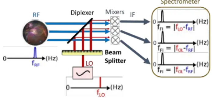
Heterodyne receivers at millimeter and submillimeter wave-lengths are widely used in astronomy [1]. They can achieve very high spectral resolution and are especially interesting for observing spectral lines in our galaxy and in other galaxies. They are usually used to observe the interstellar medium and to determine its physical and chemical properties. In heterodyne receivers, the observed signal, or radio frequency (RF) signal, is down-converted to a lower frequency without losing any amplitude or frequency information. The down-conversion is achieved by mixing the RF signal with an artificial monochromatic signal generated by a local oscillator (LO). The down-converted signal at the output of the mixer is the intermediate frequency (IF) signal (fig. 1).
Fig. 1. Down-conversion of the RF signal in a heterodyne receiver.
The heterodyne mechanism allows to down-convert a RF signal to a lower frequency (e.g. a THz signal can be down-converted to a few GHz), and to process it with a very high spectral resolution. Heterodyne receivers are widely used in astronomy between 100 GHz and 1000 GHz. A new generation of heterodyne receivers are being built for the THz regime.
This frequency range has, so far, been little observed by astronomers and it is one of the last parts of the astronomical spectrum remaining mostly unexplored (fig. 2).
Fig. 2. Transmission of the Earth atmosphere depending on the frequency.
Early THz heterodyne receivers in astronomy usually only had one spatial pixel (e.g. HIFI instrument on Herschel satellite [2]). Recently, heterodyne receiver arrays have been developed, in order to observe spectra at several positions in the sky simultaneously. Each pixel has a mixer, so, observing with several pixels involves distributing the LO beam to every mixers. Beam splitters are a good solution to divide the LO beam and to specifically illuminate each mixer (fig. 3).
Fig. 3. Use of a beam splitter in a multi-pixel heterodyne receiver.
Phase gratings [3] are already used as beam splitters in some astronomical heterodyne receivers (e.g. CHAMP [4], upGREAT [5]). However, the phase gratings currently used in THz astronomical receivers, stepped gratings [6], [7] and Fourier gratings [8], [9], have a constrained geometry which limits the beam patterns they can efficiently produce. To overcome this limitation, an iterative alternate projection-based algorithm has been developed to design structured surfaces without any geometrical constraints, and reach a good
effi-ciency for any far-field distribution. To validate this method, we have designed, simulated and built two structured surface prototypes (one in transmission and the other in reflection) able to split the LO beam into four beams [10].
II. DESIGNPROCESS
A. Structured surface design
The iterative algorithm is based on alternate projections involving inverse Fourier transforms (IFT) and Fourier trans-forms (FT). This algorithm is used to generate the phase profile for the two structured surface prototypes (a reflective one and a transmissive one) generating four beams of similar intensity at 610 GHz. More details about the algorithm itself can be found in [11].
Fig. 4. Structured surface profile calculated by the iterative algorithm.
Both prototypes are based on the same initial phase profile (fig. 4). The transmissive prototype is made of TPX®, a plastic
quite transparent at THz frequencies, and is illuminated by an orthogonal incident beam. The reflective prototype is made of brass and is illuminated by an oblique incident beam making an angle of 25◦ with the normal of the surface.
B. Electromagnetic simulation
The transmissive and reflective structured surface prototypes have been simulated (fig. 5) with a commercial electro-magnetic simulation software, FekoTM, which is based on the Method of Moments. In the simulations, the structured surfaces were illuminated by a Gaussian beam and both were able to generate a far-field pattern composed of four beams of similar intensity, as expected.
Fig. 5. Far-field beam patterns calculated with electromagnetic simulations in (a) reflection and in (b) transmission.
The beams generated by the gratings have the same Gaus-sian shape as the incoming beam, but a lower intensity. The efficiency predicted by the simulation is 81 % for the reflective prototype and 68 % for the transmissive prototype.
III. TEST OF THE STRUCTURED SURFACE PROTOTYPES
A. Mechanical design
The structured surface prototypes were milled by a 200 µm diameter end-mill. A surface accuracy of 6 µm and an average roughness inferior to 0.4 µm were measured with a profilome-ter (Dektak8). The dimensions of the two prototypes were set to be larger than 4 times the beam radius of the incoming Gaussian beam (which is 10 mm), in order to ensure that more than 99.9 % of the incoming energy is received by the structured surfaces. A picture of these two prototypes is shown in fig. 6.
Fig. 6. Pictures of the manufactured (a) reflective and (b) transmissive prototypes.
B. Efficiency test
The prototypes were tested with a 610 GHz source and the intensity of the beams was measured with a Golay cell power meter (fig. 7).
Fig. 7. Schematic of the experimental set-up to measure the radiation beam pattern of the structured surface reflector.
The source and the prototypes were positioned on a rotating platform, and the horizontal radiation pattern generated by the prototypes was measured by rotating the platform. The distance between the Golay cell power meter and the LO was kept constant, so the measured beams had always the same
radius at the input of the power meter and were comparable. The measured efficiency of the prototypes (sum of each beam’s intensity divided by the intensity of the source beam without any prototype) is 78 ± 4 % for the reflective one and 62 ± 4 % for the transmissive one. These efficiency values are very close to the ones predicted by the electromagnetic simulations.
IV. OTHER BEAM PATTERN POSSIBILITIES
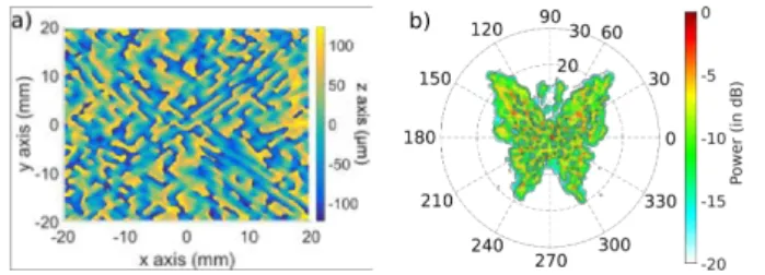
The iterative algorithm can also create structured surfaces able to generate any kind of beam pattern. To demonstrate this capability, two more complex beam patterns were given as targets to the algorithm, the name of our laboratory (LERMA), and the drawing of a butterfly. In both cases, the algorithm managed to calculate complex and non-periodic structured surfaces able to generate these beam patterns. Due to com-putational limitations, only the reflective structure has been simulated. The profiles of the structured surfaces and the corresponding far-field beam patterns simulated by FekoTM are shown in figs. 8 and 9.
Fig. 8. (a) Structured surface reflector profil generating the (b) normalized far-field, simulated with FekoTM.
Fig. 9. (a) Structured surface reflector profil generating the (b) normalized far-field, simulated with FekoTM.
These structured surfaces have not been constructed and tested yet. However, we expect simulation results to be reli-able, as the two prototypes presented in the previous section exhibit a very good agreement between the simulated and the measured beam patterns. The structured surfaces required to generate these beam patterns are very complex and were obtained because, unlike in classical phase gratings used at THz frequencies, our design procedure can be used to design non-periodic structures.
V. CONCLUSION
We have developed an iterative alternate projection-based algorithm to design structured surfaces that can be used to generate any beam pattern at GHz and THz frequencies. The
commercial electromagnetic software FekoTM was used to simulate the design and to have a precise estimation of its efficiency. In order to validate our approach, we designed, manufactured, and tested two prototype structured surfaces for 610 GHz, able to split one incoming beam into four beams. The fabricated prototypes have a measured efficiency of 78 % (for the reflective structured surface) and 62 % (for the transmissive structured surface). These results are very close to the simulations and confirm our algorithm and simulation tool. Therefore, the structured surfaces are ready to be used in the next generation of astronomical array receivers as beam dividers, but also in any other GHz or THz application where it is required to generate a custom beam pattern.
ACKNOWLEDGMENT
This work was funded by the French Space Agency (CNES) and the Laboratory for Studies of Radiation and Matter in Astrophysics (LERMA).
REFERENCES
[1] G. Beaudin and P. Encrenaz, Fundamentals of receivers for terahertz systems. J. M. Chamberlain and R. Miles, 1997.
[2] F. P. Helmich on behalf of the HIFI consortium, “Herschel-HIFI: The Heterodyne Instrument for the Far-Infrared,” EAS Publications series, vol. 52, pp. 15–20, 2011.
[3] J. N. Mait, “Understanding diffractive optic design in the scalar domain,” J. Opt. Soc. Am. A, vol. 12, pp. 2145–2158, 1995.
[4] R. G¨usten, G. A. Ediss, F. Gueth, K. H. Gundlach, H. Hauschildt, C. Kasemann, T. Klein, J. W. Kooi, A. Korn, I. Kramer, H. G. LeDuc, H. Mattes, K. Meyer, E. Perchtold, M. Pilz, R. Sachert, M. Scherschel, P. Schilke, G. Schneider, J. Schraml, D. Skaley, R. Stark, W. Wetzker, H. Wiedenhover, W. Wiedenhover, S. Wongsowijoto, and F. Wyrowski, “CHAMP — The Carbon Heterodyne Array of the MPIfR,” Proceedings of SPIE, vol. 3357, pp. 167–177, 1998.
[5] C. Risacher, R. G¨usten, J. Stutzki, H. W. H¨ubers, P. P¨utz, A. Bell, D. B¨uchel, I. Camara, R. Castenholz, M. Choi, U. Graf, S. Heyminck, C. Honingh, K. Jacobs, M. Justen, B. Klein, T. Klein, C. Leinz, N. Reyes, H. Richter, O. Ricken, A. Semenov, and A. Wunsch, “The upGREAT Heterodyne Array Receivers for Far Infrared Astronomy,” 39th International Conference on Infrared, Millimeter, and Terahertz waves (IRMMW-THz), pp. 1–2, 2014.
[6] H. Dammann and E. Klotz, “Coherent optical generation and inspection of two-dimensional periodic structures,” Optica Acta, vol. 24, no. 4, pp. 505–515, 1977.
[7] J. N. Mait, “Design of Dammann gratings for two-dimensional, non-separable, non-centrosymmetric responses,” Opt. Lett., vol. 14, pp. 196– 198, 1989.
[8] U. U. Graf and S. Heyminck, “Fourier Gratings as Submillimeter Beam Splitters,” IEEE Trans. on Antennas and Propagation, vol. 49, no. 4, pp. 542–546, 2001.
[9] S. Heyminck and U. U. Graf, “Array-Receiver LO Unit using collimating Fourier-Gratings,” 12th International Symposium on Space Terahertz Technology, pp. 563–570, 2001.
[10] F. Defrance, “Instrumentation of a 2.6 THz heterodyne receiver,” Ph.D. dissertation, UPMC Universit´e Paris 6, Dec. 2015.
[11] F. Defrance, M. Casaletti, J. Sarrazin, M. C. Wiedner, H. Gibson, G. Gay, R. Lef`evre, and Y. Delorme, “Structured surface reflector design for oblique incidence beam splitter at 610 GHz,” Optics Express, vol. 24, no. 18, pp. 20 335–20 345, Aug. 2016.