First International Conference on Bio-based Building Materials June 22nd - 24th 2015 Clermont-Ferrand, France
EFFECTS OF SHELL ELEMENT ON SHELLED COMPRESSED EARTH
MASONRY UNITS
C. Egenti*, J. M. Khatib
Faculty of Science and Engineering, School of Architecture and Built Environment, University of Wolverhampton, Wulfruna Street, Wolverhampton, WV1 1LY, United Kingdom
*Corresponding author; e-mail: C.Egenti@wlv.ac.uk
Abstract
Shelled compressed earth block is an earth block of an outer shell of optimum cement content, and an inner core of less or no cement content – compressed into a unit block. The shell element was introduced for durability and weathering resistance with less overall cement. This study is carried out to assess the extent to which, the shell element impacted on the above properties. Thus establishing the specific impacts of the shell element on the overall properties of shelled compressed earth masonry unit. Experimental research plan was designed using relevant material compositions, shelled and unshelled, for basic masonry tests like compressive strength, capillary water absorption, wet and dry abrasion. Results revealed a significant effect of shell element on the overall physical properties with less overall cement content.
Keywords: Sustainability; Shelled earth block; Weathering resistance; Durability.
1 INTRODUCTION
The durability of earth walls is dependent on how well the forces of erosion of its surface is resisted. The principal mechanism causing surface of earth walls is the release of the kinetic energy from rain drops impacting on the surface [Heathcote 1995]. Brooks [2003] corroborated this and further identified a second mechanism which is the erosion due to concentrated water flow on areas of the wall. The inclusion of binder like cement, lime or bitumen to earth before ramming transforms earth from its unstable state of strength and volume to a more suitable building material [Hammond 1973; Hammond 1991; Ayensu 1996; Gidigasu 1993]. Chemical and mechanical stabilisation greatly improves the weather resistant ability of earth walls [May, 1984; Smith, 1987]. The soil composition and mineralogy are of relevance in selection of appropriate binder. Cement is more suitable for a soil with a higher percentage of sand, while lime reacts slowly and more effectively with clayey soil to form a stable pozzolanic material [Rigassi 1985]. The quantity of binder for optimum performance changes with soil characteristics [Egenti 2013]. Generally, 5 per cent to 8 per cent cement is recommended for the satisfactory performance of compressed earth walls [Venkararama 1987; Asamoah-Boadu 2001]. However, the appearance of defects still occur frequently thereby creating social issues. It is therefore an undisputable case of high stabilisation against social rejection. Earth stabilisation for
building purposes is a middle path to modernity, which is inevitable if earth will become a popular material in the contemporary context. Egenti [2014] considered issues relating to adequacy and durability of earth walls, and the corresponding cost implications; the concept of a Shelled Compressed Earth Block (SCEB) evolved from research investigation aimed at the reduction of the amount of cement used in earth wall construction.
2 SHELLED COMPRESSED EARTH BLOCK (SCEB)
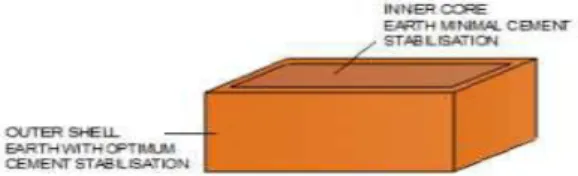
The Shelled Compressed Earth Masonry Unit is an earth block of two layers of different percentages of stabilisation. The inner layer/core was stabilised with zero or low cement; and the outer layer/shell, was stabilised with higher cement content – all compressed mechanically into a single unit block. Fig. 1 shows an illustration of unit and block wall of SCEB. The concept evolved with the intention of giving adequate stabilisation to the exposed part of compressed earth block with less overall cement content and cost.
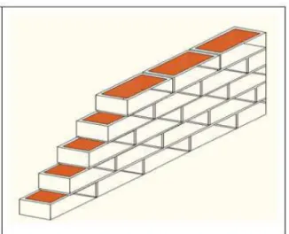
Fig. 2: Masonry framework in running bond
The arrangement of the blocks in stretcher or running bond, as shown in Fig. 2, revealed a composition of masonry framework of shell in a supportive and interwoven structure and the inner core in a protective confinement [Egenti 2014].
2.1 Structure of SCEB Masonry Unit
The structure of the laboratory specimen is as shown in Fig. 3. Shell thicknesses was 13mm on the stretcher and header of the block. The headers are always adjacent and bedded in a strengthening thickness of mortar, hence a smaller shell thickness.
100
150x100x75mm - Laboratory specimen for Pilot Study.
13 124 13 13 74 13 13mm thick shell Inner Core Fig.3: Designed and configuration of laboratory
specimen
The shell in the above shelled block configuration constitutes 39 per cent, while the inner core is 61 per cent of the volume of the masonry unit.
Tab. 1: The designed data of the laboratory specimen of SCEB
Dimensions (mm) Thickness of shell (mm)
Volume (mm3) Length Width Height Shell Core
150 100 75 13 39% 61% The configuration and properties of laboratory specimen of SCEB, was examined using selected masonry tests, which revealed the effect or impact of the shell element in shelled compressed earth block. 3 MATERIALS AND METHODS
Aviele laterite soil was used for this investigation. A cohesive, gravelly, lateritic soil of 38 per cent passing. The particle size distribution, plastic and liquid limit are as shown in Figs. 4 and 5. The plasticity index is 15.
Fig. 4: Particle size distribution chart of Aviele laterite soil [Egenti 2013]
Fig. 5: Plastic and liquid limit for Aviele laterite soil [Egenti 2013]
Specimens of shelled compressed earth blocks were produced from the above Aviele soil using a mechanical kit designed and fabricated as described in Egenti [2014]. Specimens were cured for the first seven (7) days in sealed polythene bags; and air dry at ambient room temperature of 20 ± 18oC and maximum relative humidity of 60 ±5% until the 28th day to achieve maximum performance. Drying to constant mass is always in a ventilated oven at 75oC; after which specimens are allowed to cool to ambient room temperature. Compressive strength test, Initial rate of water absorption, Surface abrasion and Flexure tests were conducted on block specimens of the following compositions: Unstablised (0%) cement CEB, 3 - 15% cement content in shell and 0% cement in inner core. Compressive strength test was conducted in accordance with BS EN 772-1:2011. The normalised compressive strength, fb, was obtained by multiplying the air-dry compressive strength reading with a shape factor, d, of 0.9 for the laboratory specimens’ width of 100mm and height of 75mm [BS EN 772-1:2011].
Initial rate of water absorption by capillary action was assessed for SCEB specimens of varying cement content (0 to 15 per cent) in shell in accordance with BS EN 772-11:2011. The apparatus and set up for initial rate of water absorption are as shown in Figs. 6 and 7.
Fig. 6: Apparatus for capillary water absorption of stabilised specimens
Fig. 7: The set up for Initial rate of water absorption test
Wet and dry abrasion by wire brush tests was conducted in accordance with ASTM D559, 1989. A stiff wire brush made of 50 of 1.6mm flat 26-gauge wire bristles assembled in 50 groups of 10 and mounted to form 5 longitudinal and 10 transverse rows is used to brush the blocks surface in a straight stroke. Two firm strokes were applied to the whole block surfaces as shown in Fig. 8. Block specimens were then submerged in water for a period of five hours after which they are returned to the oven all in a circle of 24 hours. The process is repeated for a total of 12 cycles of wetting, drying and brushing. A final mass reading is taken. The percentage of mass loss calculated using the following equation.
Eroded component (%) = x 100
Where W = Original oven dried mass and M = Final oven dried mass.
Percentage of eroded mass was plotted against percentage of cement stabilisation.
Fig. 8: Wire brush test of surface abrasion 4 RESULTS AND DISCUSSIONS
The results here discussed in the context of the impact of the shell element on the properties of Compressed Earth Block.
4.1 Strength
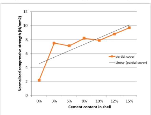
The introduction of cement-stabilised shell had a significant effect on the normalised compressive strength of block as can be appreciated in Fig. 9.
Fig. 9: Compressive strength increased with increase in cement content in the Shell
The above chart shows that at zero per cent cement content, the normalised compressive strength was 1.9 N/mm2. With an introduction of a shell of 3 per cent cement content, the normalised compressive strength increased to about 5N/mm2; and about 6.5N/mm2 with 5 per cent cement in shell. The compressive strength of compressed earth blocks increased considerably with the introduction of an outer shell of stabilised earth. The overall strength of the masonry units further increased with increase in stabilisation of the outer shell.
4.2 Shear plane failure of Shelled Compressed Earth Block
The shear pattern of Shelled compressed earth block upon failure showed a significant pressure on the shell as shown in Fig. 10. The shear lines cut through the inner core (dark colour) and the outer shell (lighter in colour). This is an indication that the shell and the core co-worked together in resisting the load.
Fig. 10: Failure pattern of SCEB [Egenti 2014]
The effect of the introduction of shell to the normal CEB had a significant effect on the compressive strength of the masonry unit. The nature of the shear failure showed an effective and supportive behaviour of the inner and outer layer co-working for loadbearing.
4.3 Water absorption
The mean of initial rate of water absorption was observed to reduce with the increase in cement content of the shell as shown in Figure 11. A comparison of rate of water absorption, by capillary action, of blocks with different percentages of shell stabilisation is shown in Fig. 12.
Fig. 11: Initial rate of water absorption of SCEB with shell of varying cement content.
Fig. 12: Comparison of rate of water absorption of SCEB with shell of varying cement content [Egenti
2014]
The unstablised specimens had a very high rate of absorption and disintegrated in less than 10 minutes. The 3 per cent stabilization made a big difference, as it remained firm through the handling and the 60 minutes duration of the experiment. The volume change, of the inner core of unstabilised earth, due to capillary water absorption was insignificantly low that the weak shell of 3 per cent cement content did not crack.
4.4 Surface Resistance
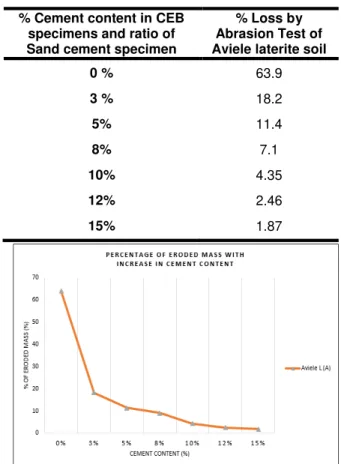
The result of abrasion test by wire brush is shown in Tab. 2 and Fig. 13. The result of the Abrasion Test with wire brush was analysed in comparison with Portland Cement Association [1971] recommendation of acceptable mass loss of less than 14 per cent for sandy earths and 7 per cent for clayey earths. Fitzmaurice [1958] suggested the following limits for weight loss of 5 per cent for permanent buildings in Urban Areas in regions with annual rainfall greater than 500mm and 10 per cent in regions with annual rainfall less than 500 mm. The percentage loss by abrasion reduced with increase in cement content of shell. The use of high cement content in shell provides quality and wear free surface. This is achievable at lower cost as the
overall cement content is reduced. A 10 per cent cement content in shell and 3 per cent in the core gives a 5.7 per cent of overall cement content; based on the proportional volume of 39 per cent and 61 per cent of shell and core in the structure of the laboratory specimen of SCEB.
Tab. 2: Results of surface resistance tests % Cement content in CEB
specimens and ratio of Sand cement specimen
% Loss by Abrasion Test of Aviele laterite soil
0 % 63.9 3 % 18.2 5% 11.4 8% 7.1 10% 4.35 12% 2.46 15% 1.87
Fig. 13: Percentages of erosion of stabilised CEB made from Aviele laterite earth and Ubiane earth
with different cement additions. 5 SUMMARY
Compressed Earth Block shelled for surface protection at low cost. This paper which sets out to investigate the impact of the shell on the overall properties of shelled compressed earth, revealed a very significant change in compressive strength from 1.9 N/mm2 to 5 N/mm2 by the introduction of a shell of 3 per cent cement content and about 6.5N/mm2 with 5 per cent cement in shell. The initial rate of water absorption by capillary action reduced from 1.9 kg/(m2 x min) for 0 per cent cement content in shell, to 0.8 kg/(m2 x min) with 10 per cent cement in shell. The percentage loss by abrasion reduced from 69 per cent for 0 per cent stabilisation to 4.5 per cent with 10 per cent cement stabilisation of shell. Thus, a high performance with a reduction in overall cement content is achievable by the use of shelled compressed earth block.
6 REFERENCES
[Asamoah-Boadu 2001] Asamoah-Boadu, N. and Afukaar, F.K. Application of earth building materials for low-income housing. Journal of Applied Science
[ASTM D559] ASTM Standard (1989), Standard test
methods for wetting and drying compacted soil-cement mixtures. ASTM International, West
Conshohocken, PA, 1989. www.astm.org.
[Ayensu 1996] Ayensu, A. Laterites as construction materials for rural housing. New and Advanced
Materials Emerging Technology Series , 3pp. 42-45.
[Brooks 2003] Brooks, K.N., Ffolliottet, P.F., Gregersen, H.M. and DeBano, L.F. Hydrology and
Management of Watersheds . Second ed. Hoboken,
USA: Wiley. p. 574.
[BS EN 772-1:2011] British Standard Institution (2011) Determination of compressive strength [online]. BSI Group. [Accessed 20 March 2012]. Available at <http://www.bsi-global.com>.
[BS EN 772-11:2011] British Standard Institution (2011) Determination of water absorption of aggregate concrete, autoclaved aerated concrete, manufactured stone and natural stone masonry units due to capillary action and the initial rate of water absorption of clay masonry units [online]. BSI Group. [Accessed 20 March 2012]. Available at <http://www.bsi-global.com>.
[Egenti 2013] Egenti, C., Khatib, J. and Oloke, D. Appropriate Design and Construction of Earth Buildings: Contesting Issues of Protection against Cost. African Journal of Basic and Applied Sciences, 5(2), pp. 102-106.
[Egenti 2014] Egenti, C., Khatib, J.M. and Oloke, D. (2014) Conceptualisation And Pilot Study Of Shelled Compressed Earth Block For Sustainable Housing In Nigeria. International Journal of Sustainable Built
Environment [online], Available at: http://www.sciencedirect.com/science/article/pii/S221 2609014000223;
[Fitzmaurice 1958] Fitzmaurice, R., Manual on
stabilized soil construction for housing. Technical
assistance program, United Nations, New York. [Gidigasu 1993] Gidigasu, M.D. Lateritic Materials in Rural Housing Construction in Ghana, Final Report.
Laterite Housing Ghana Project, 1pp. 23-98.
[Hammond 1973] Hammond, A.A. Prolonging the life of earth building in the tropics. Building Research
Practice, BRRI CP/4 pp. 154-163.
[Hammond 1991] Hammond, A.A. Housing in Africa, problems, prospects and strategies. Journal of the
Network of African Countries on Local Building Materials and Technologies, 1(No. 4), pp. 1-6.
[Heathcote 1995] Heathcote, K.A. Durability of Earthwall Buildings. Construction and Building
Materials, 9(3), pp. 185-189.
[May 1984] May, G.W. Standard Engineering for earth buildings in McHenry,P. G.(ed). Adobe and
Rammed Earth Buildings. New York: John Wiley and
Sons.
[Portland Cement Association 1971] Portland Cement Association, Soil-Cement Laboratory Handbook. Engineering Bulletin, EB 052.
[Rigassi 1985] Rigassi, V. Compressed earth blocks:
Manual of production - Volume 1 (Translated by C.
Norton.) Germany: GATE & BASIN.
[Smith 1987] Smith, R.G., Small scale manufacture of stailised soil blocks. Geneva: ILO Publications. [Venkararama 1987] Venkararama, R.B. and Jagadish, K.S. Spray erosion studies on pressed soil blocks. Building Environs, 22(2), pp. 135-140. [Walker 2002] Walker, P. and Standards Australia,
The Australian Earth Building Handbook (HB195)