Experimental
and
comparative
study
of
the
thermomechanical behaviour and the residual one of the
textile reinforced concrete (TRC) subjected to high
temperature loading
Tala TLAIJI
1, Xuan Hong VU
1, Amir SI LARBI
2,
Emmanuel FERRIER
11Université de Lyon, Université Lyon 1, Laboratory of Composite Materials for Construction (LMC2), 82 bd Niels Bohr, F-69622 Villeurbanne, France. Mail : tala.tlaiji@etu.univ-lyon1.fr, xuan-hong.vu@univ-lyon1.fr,
emmanuel.ferrier@univ-lyon1.fr
2
Univ Lyon, ENISE, LTDS, UMR 5513 CNRS, 58 rue Jean Parot, 42023 Saint-Etienne Cedex 2, France. Mail :
amir.si-larbi@enise.fr
Abstract. The studied TRC composite is made with a cementitious matrix and GRID alkali-resistant glass textile. Each TRC specimen is subjected to one of these two loading paths: thermomechanical test or residual resistance one. In both tests, the temperature is firstly increased to the required target degree (20°C, 75°C, 150°C, 300°C, 400°C or 600°C) and is then kept constant for one hour. In thermomechanical test, the axial tensile force is then applied directly to the specimen and increases monotonically until the maximum one that the specimen can resist. In the residual resistance test, TRC specimens are then naturally cooled in the furnace during 15 hours. After cooling, the temperature within the TRC specimens is equal to the temperature of the ambient air (20°C). The preheated-cooled TRC specimens are then tested at 20°C by a monotonic axial tensile loading until its rupture in order to identify its residual behaviour. These two loading paths allowed characterizing thermomechanical and residual behaviours of the TRC composite. They also allowed comparing the stress/strain curves and the characteristics of this material as a function of the target temperature level and of the loading paths.
Résumé. Le composite TRC étudié est composé d’une matrice cimentaire et d'un textile grille verre AR. Chaque éprouvette TRC est soumise à l'une de ces deux sollicitations : essai thermomécanique ou essai de résistance résiduelle. Dans les deux protocoles d’essai, la température est tout d’abord augmentée jusqu’à un niveau cible désiré (20°C, 75°C, 150°C, 300°C, 400°C ou 600°C) et ensuite maintenue constante pendant une heure. Dans l’essai thermomécanique, une force de traction axiale est ensuite directement appliquée sur l'échantillon et augmente de façon monotone jusqu'à la rupture. Dans l’essai de résistance résiduelle, les éprouvettes de TRC sont ensuite naturellement refroidies dans le four pendant 15 heures. Après refroidissement, la température au sein des échantillons est égale à la température de l’air ambiant (20°C). Les éprouvettes préchauffées-refroidies sont ensuite testées à 20°C en chargement de traction axiale monotone jusqu’à sa rupture afin d’identifier son comportement résiduel. Ces deux trajets de chargement ont permis de caractériser les comportements thermomécanique et résiduel du composite TRC.
KEYWORDS: textile reinforced concrete (mortar), high temperature effect, thermomechanical test, residual resistance test
MOTS-CLÉS: Béton (ou mortier) renforcé par des textiles (TRC), effet de la haute température, essai thermomécanique, essai de résistance résiduelle
1. Introduction
Textile reinforced concrete (TRC) is a new, effective and innovative generation of cementitious material with enhanced tensile strength and ductility [MEC 2013] and [SOR 2009]. It consists of fibers reinforcement which ensures the mechanical strength -e.g. glass or carbon fibers- and a protection called matrix, which is typically a plastic, thermoplastic or thermosetting material and ensures the retransmission of efforts towards the reinforcement. TRC combines the favorable material properties of these two components. This composite material has been shown to have the potential to be used to design slender, lightweight, modular and freeform structures. This material eliminates the risk of corrosion and provides high strength in compression and also in tension [ORL 2011] and [BRA 2006]. It has also been proven to be a suitable solution for strengthening and repairing structural elements [ORT 2008]. Another important function is desired in textile fireproof function. When structures are subjected to fire, they are simultaneously submitted by very high temperature levels (potentially up to 1200°C) and mechanical loadings. For this, TRC presents, compared to polymer matrix composites generally used in the rehabilitation context, an ecological footprint more appropriate with the preoccupation or the requirement of sustainable development and the imperative of hygiene and security (without solvent, absence of toxic fumes, absence of volatile organic compounds) and a high performance composites that can present an important uniaxial tensile strength [PEL 2005] and [VER 2014]. Until now,
studies on the behaviour of textile reinforced concrete under fire loadings [BUT 2010] and [REI 2008] are still rare. There are few studies conducted on residual behaviour of TRC after exposure to a thermally heating process (up to a target temperature) and to a non-controlled cooling process [RAM 2015], [XU 2014], [COL 2011] [BLO 2011], [TAN 2007]. These studies have allowed predicting the residual behaviour of the TRC composite after being exposed to fire and then cooled. Few studies have been done on the thermo-mechanical behaviour of TRC and even less about the comparison between this one and the residual behaviour of TRC. This work will contribute to propose an experimental data and to contribute to compensate the lack of scientific knowledge of the mentioned problems. The aim of this article is to compare the thermo-mechanical behaviour and the residual one of the TRC that is subjected to different temperature loadings (20°C, 75°C, 150°C, 300°C, 400°C, 600°C) without and with cooling respectively before the mechanical test. In the following, this paper presents an experimental procedure in which the device, the preparation of test specimens, and the test loading path are detailed. It then describes and discusses the results of tests carried out on the studied materials and the obtained macro-scale characterization. Failure modes of the tested samples are also presented. The presentation of the main conclusions and the outlook of future work end this article.
2. Experimental procedure: 2.1. Experimental device
The machine Zwick 20kN-furnace (Figure 1) is used in this study to test TRC specimens. It is fitted with a small furnace that can provide a high temperature, potentially up to 1200°C. The maximum velocity of temperature rise in the furnace is 30°C/ minute. The specimen is placed in the middle of the furnace that measures 300x100mm and is attached by two “ball joint” loading heads, designed by a previous study [CON 2011], that allow applying a tensile force and controlling the alignment of the specimen.
(a) (b)
Figure 1. (a) The machine Zwick 20kN-furnace; (b) Furnace and specimen installed for a thermomechanical
tensile test
This machine is equipped with a laser sensor (with a green-coloured light) that measures the longitudinal strain of the specimen during mechanical loading. There is an opening area (rectangular form) on the sidewall of the oven that allows for the passing of laser bobbins that are emitted by the laser sensor during the test (see Figure 1b). Two laser bobbins, each having an area of approximately one square centimetre, are used (Figure 1b). Laser bobbins are directly projected on the specimen surface through a transparent glass (held at high temperature) and the opening area of the furnace. During a test, images that are taken by the two cameras of the laser sensor before and after the displacement of the concerned points are processed by the machine to provide a relative displacement between two laser bobbins. The strain is calculated as the ratio of the relative displacement of two laser bobbins and their initial distance. When the tested material is homogeneous as TRC, the measurement of the laser sensor can provide the axial strain of the part of the specimen placed in the
on measurements of both opposite main sides to suitably characterize composite TRC [CON 2011]. To work around this limit, measurement will be taken on one of the two "side faces" or "small faces" of the specimen to cover, in large part, imperfections related to the main faces. The force sensor and the laser sensor of this machine, placed outside the furnace, are regularly calibrated to ensure their reliability. The tests and validation of the measurement of specimen, obtained by the laser sensor, are previously described [VU 2013, NGUYEN 2013]. This machine is automated and controllable and can simultaneously generate the thermal and mechanical loadings. During the thermal loading in the furnace, the temperature rise rate in the furnace is programmable, by testXpert software, and measured using three thermocouples installed on the specimen at equal distances to ensure that the temperature in the furnace remains homogeneous in all areas during the test.
2.2. Materials
The main composition of the TRC material tested in this study consists of a cementitious matrix and three layers of GRID alkali-resistant (AR) glass textile. The rheology of the fresh cementitious matrix has been experimentally identified (Table 1). The compressive strength and the tensile strength of this matrix, experimentally identified, are respectively 23MPa and 4,5MPa. The physical and mechanical properties of a single fibre of the alkali-resistant glass is presented on Table 2. This type of glass textiles was chosen because they have excellent fire resistance (up to 860°C) and they do not stretch and shrink after exposure to extremely high or low temperatures [HEXCEL]. The alkali-resistant (AR) nature of the glass textile also facilitates a very good capacity (compared to E-glass) to resist degradation in an alkaline environment. Other criteria have led to the choice of the above reinforcements: nominal weight (g/m2), mortar penetration ability, cutting facility, implementation conditions, etc. The textile type grid AR-glass used in this study has the same thread in two directions of the grid. Its mechanical properties are shown in Table 3. This grid is large, the opening between the meshes axis is 8x8mm which allows the passage of small aggregates. The reinforcement ratio of the textile for the studied TRC is 5,7% (Vf = textile volume/TRC volume = 5.7%). The cementitious matrix and the
reinforcement textiles are cast in a mold to obtain a plate of TRC having the dimension 800mmx 500mmx 5mm (length × width × thickness). After 7 days, the rectangular plates were cut, resulting in specimens of 700 mm × 45 mm × 5 mm (length × width × thickness). The TRC material (P3AR) is made and kept in the laboratory atmospheric condition, stored at ambient temperature for at least a month before testing so that the TRC obtains the maximum mechanical strength. To prepare the specimen for the test, four aluminum plates are glued to the ends of each specimen using the adhesive Etancol 492, of an epoxy resin type, to ensure transfer efficiency of the mechanical load. The choice of the aluminum plate length (70 mm) is simply based on the bearing capacity of the traction machine and the shear strength of the adhesive Etancol 492 (its properties are presented on Table 4). At least 3 days after the bonding, the TRC sample is drilled at each end to be compatible with the used “ball joint” loading heads.
Table 1. Mortar characterization
Mortar characterization Plasticity (or
consistence)
Measurement of the plasticity of the mortar using flow table (cm)
14 Measurement the plasticity of the mortar using the plunger (cm) 2
Time of the workability (second) of the mortar 28
Control of entrained air volume (%) 12
Density (g/cm3) 1.75
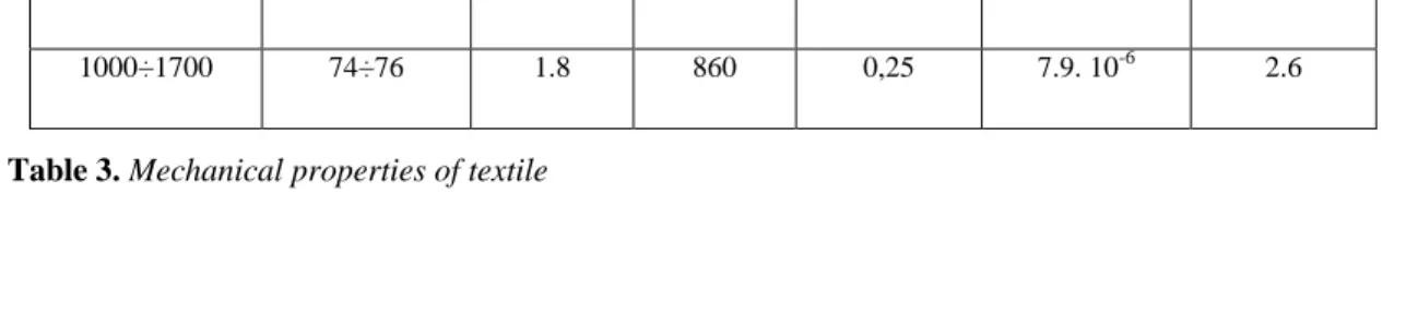
Table 2. Physical and mechanical properties of a single fibre of the alkali-resistant glass
Tensile resistance (MPa) Elastic modulus (GPa) Strain at rupture (%) Softening point (°C) Poisson coefficient Thermal expansion coefficient Density (kg/dm3) 1000÷1700 74÷76 1.8 860 0,25 7.9. 10-6 2.6
Reference
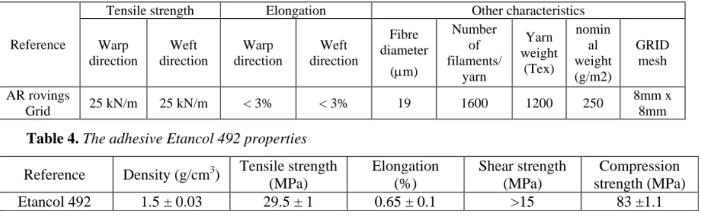
Tensile strength Elongation Other characteristics
Warp direction Weft direction Warp direction Weft direction Fibre diameter (m) Number of filaments/ yarn Yarn weight (Tex) nomin al weight (g/m2) GRID mesh AR rovings Grid 25 kN/m 25 kN/m < 3% < 3% 19 1600 1200 250 8mm x 8mm Table 4. The adhesive Etancol 492 properties
Reference Density (g/cm3) Tensile strength (MPa) Elongation (%) Shear strength (MPa) Compression strength (MPa) Etancol 492 1.5 ± 0.03 29.5 ± 1 0.65 ± 0.1 >15 83 ±1.1
The Table 5 presents the tests carried on textile reinforced mortar (called P3AR) with thermomechanical regime (TM) and residual resistance regime (RR). For each target temperature level (except for 600°C), at least 2 samples were tested.
Table 5. Tests carried on textile reinforced mortar with thermomechanical regime (TM) and residual resistance
regime (RR); For the tests carried out on the specimens (*), only the ultimate axial stress is exploitable.
Specimen reference Target temperature (°C) Heating rate (°C/minute) Exposure duration at target temperature (hour) Number of tests Thermomechanical (TM) P3AR_T25 (a,b) 25 0 / 2 P3AR_T75 (a,b,c*) 75 2,5 1 3 P3AR_T150(a,b,c*) 150 5 1 3 P3AR_T300 (a,b) 300 10 1 2 P3AR_T400 (a,b) 400 13 1 2 P3AR_T600(a) 600 20 1 1 Residual Resistance (RR) P3AR_T75 (a,b) 75 2,5 / 2 P3AR_T150 (a,b,c*,d*) 150 5 1 4 P3AR_T300 (a,b,c*,d*) 300 10 1 4 P3AR_T400(a,b) 400 13 1 2 P3AR_T600(a) 600 20 1 1 2.3. Experimental testing
There are two loading paths used in this study: direct thermomechanical test and residual resistance test. The common point between these two loading paths is the thermal loading. P3AR specimens are respectively heated up to 75°C, 150°C, 300°C, 400°C and 600°C. For technical reasons, the furnace requires approximately 30 minutes to reach the target temperature to ensure its good operation and good homogeneity of the temperature around the entire portion of the sample placed in the furnace. First, all samples are subjected with a heating increase rate in the furnace (ranging from 2,5°C/minute to 20°C/minute) corresponding to each temperature level (ranging from 75°C to 600°C), and when the temperature reached the target value, it is then kept constant for one hour. In thermomechanical test (figure 2), the axial tensile force is directly applied to the specimen after one hour of exposure at target temperature. It monotonically increases until the maximum force that the specimen can be resisted. On the other hand, in the residual resistance tests (figure 3), the same target temperature level and the same exposure duration (one hour) as thermomechanical tests are applied. Specimens are then subsequently cooled by a natural process inside the furnace (without any control), the axial tensile loading is then applied after 15 hours.
These tests have allowed obtaining residual behaviour of the composite material after the heating-cooling processes. For both these two loading paths, the axial strain of the specimen is measured thanks to the laser sensor from the beginning of the increase of the axial tensile loading (third phase of the test) until the composite rupture. The axial tensile force and the axial strain of the specimen were recorded for both the direct thermomechanical test and the residual resistance one. These tests have allowed determining the stress/strain curves and the characteristics of the material as a function of the target temperature level.
3. Test results
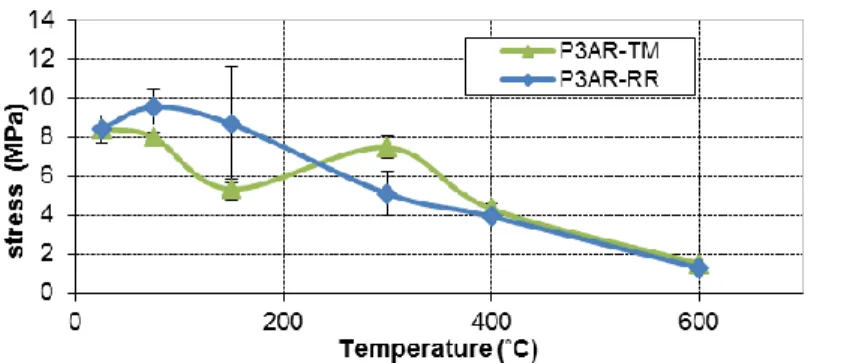
The studied TRC (P3AR) shows to be strongly affected by thermal processing when submitted to a tensile loading. The evolution of the axial stresses of the P3AR composite as a function of axial strains is provided in figure 4.
Figure 4. Thermomechanical and residual behaviours of the P3AR composite in different target temperature
levels
RR
Figure 4 compares the results of the thermomechanical (TM) tests and of the residual resistance (RR) ones for each target temperature level (25°C, 75°C, 150°C, 300°C, 400°C and 600°C). It is observed that the behaviour of the P3AR composite significantly varies as function of the loading path when the target temperature level changes from 75°C to 300°C. For the target temperature levels ranging from 75°C to 150°C, the maximum stress of the P3AR composite, obtained by the residual resistance test, is greater than that obtained by the thermomecanical test. However, for the same target temperature levels, the measured maximum axial strain, obtained by the residual resistance test, is lower than that obtained by the thermomecanical test. For target temperature levels ranging from 300°C to 400°C, the behaviours of the studied TRC, obtained by two loading path, seem to be not very different. For 600°C, the maximum stress and the measured maximum axial strain, obtained by two loading path, are quite small.
Figure 5 and Figure show the results of the direct thermomechanical tests (TM) and the residual resistance (RR) ones in terms of the average stress (Figure ) and the average strain (Figure ), obtained from different tests presented in Table 5, as a function of the target temperature level ranging from 20°C to 600°C. This figure shows that the average strength of this composite slightly reduces when it is subjected to temperatures below 150°C in thermomechanical tests. However the positive influence of the preheating, up to 75 °C or up to 150 °C, of the P3AR composite specimens on the maximal strength and the maximal axial strain of this material is clearly noticeable for the residual tests. The phenomenon observed on the residual tests, for the target temperature levels ranging from 20°C to 150°C, is consistent with that observed in the literature [RAM 2015], [XU 2014], [COL 2011] [BLO 2011], [TAN 2007]. For the target temperature levels ranging from 150°C to 300°C, the ultimate tensile strength of the P3AR composite rapidly decreases in the residual resistance tests and slightly increases in the direct thermomechanical tests. And for target temperature levels ranging from 300°C to 600°C, a severe loss in the ultimate tensile stress is observed for both these loading paths. Furthermore, this study shows that for the same target temperature levels (ranging from 20°C to 150°C), the ultimate strain of the P3AR specimen, obtained by the thermomechanical test, is significantly higher than the one of the preheated-cooled P3AR specimen (at 150°C, the ratio between these ultimate axial strains is about 2 times). The difference between the ultimate strains of the P3AR composite, obtained by the two studied loading paths, gradually reduces when the target temperature level increases from 150°C to 600°C. This study clearly shows that, for target temperature levels below 400°C, the thermomechanical behaviour of the studied TRC composite is significantly different to its residual one. Above this target temperature level (400°C), the thermomechanical behaviour of the studied TRC composite seems be similar to its residual one.
Figure 5. Average strength as a function of target temperature levels for the thermomechanical (TM) tests
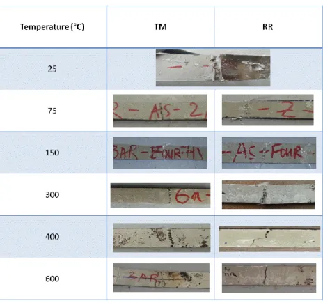
4. Failure modes
The observations after the tests (Figure ) show that the rupture of P3AR specimens occurs in the middle of the sample in different temperature levels and in different loading paths except at 20°C, it is close to loading heads. The failure modes of the P3AR specimens appear with a visible macro crack and more micro cracks. For P3AR specimens tested in the thermomechanical regime, the visible macro crack is almost perpendicular with the tensile loading axis. For P3AR specimens tested in the residual regime for the target temperature levels ranging from 75°C to 600°C, the visible macro crack is rather inclined with respect to the tensile loading axis. These results show that the inclination of the visible macro crack of P3AR specimens, tested in the residual regime, seems to be related to the process of the preheating/cooling of this material.
Figure 7. Failure mode in different target temperature levels and different loading paths (RR: residual
resistance test; TM: thermomechanical test).
6. Conclusion
This study concerns the experimental and comparative study of the thermomechanical behaviour and the residual one of the textile reinforced concrete (TRC) subjected to high temperature levels varying from 25°C to 600°C. The TRC composite is made with a cementitious matrix and three layers of alkali-resistant (AR) GRAD glass textile. The results of this work show that during a rise in target temperature level, the behaviour of the studied TRC (called P3AR) changes. They also show the different behaviour of this material as function of the loading paths (the direct thermomechanical test or the residual resistance one). In the residual resistance tests, the heating-cooling processes of the studied TRC at few temperatures ranging from 20°C to 150°C has a positive effect on the mechanical performance of the studied TRC. This heating-cooling processes leads to gradually increase the residual ultimate strength and the measured maximum axial strain of the TRC composite. When target temperature levels increase from 150°C to 600°C, the residual ultimate strength and the measured maximum axial strain of the P3AR composite gradually reduce. In thermomechanical tests, the ultimate strength of the P3AR composite slightly changes when target temperature levels rise from 20°C to 300°C and considerably reduces when the target temperature levels increase from 300°C to 600°C. In this loading path, the measured maximum strain of the P3AR significantly increases when target temperature levels rise from 25°C to 150°C and gradually reduces for the target temperature levels greater than 150°C. This study also shows that for the same target temperature levels (ranging from 20°C to 150°C), the ultimate strain of the P3AR specimen, obtained by the thermomechanical test, is significantly higher than the one of the preheated-cooled P3AR specimen (at 150°C, the ratio between these ultimate axial strains is about 2 times). The difference between the ultimate strains of the P3AR composite, obtained by the two studied loading paths, gradually reduces when the
target temperature level increases from 150°C to 600°C. For the target temperature level greater than 400°C, the thermomechanical behaviour of the studied TRC composite seems be similar to its residual one.
7. Acknowledgment
This research was supported by LMC2 laboratory for the experimental work. This research has also been realized with the financial support from the European Regional Development Fund (ERDF or FEDER) of the Rhône-Alpes-Auvergne region, France. We would like to thank the team of technicians of the Civil Engineering Department of the IUT Lyon 1, University Lyon 1 for their technical support.
8. Bibliography
[BLO 2011] BLOM J., ACKEREN J.V., WASTIELS J., “Study of the bending behaviour of textile reinforced cementitious composites when exposed to high temperatures”. Proceeding of the 2nd International RILEM Conference on Strain
Hardening Cementitious Composites (SHCC2-Rio), 2011.
[BRA 2006] BRAMESHUBER W., “Textile Reinforced Concrete, State-of-the-Art Report of RILEM Technical Committee 201-TRC”, RILEM Report, n°36, 2006, Bagneux, France.
[BUT 2010] BUTTNER T., ORLOWSKY J., RAUPACH M., «Fire resistance tests of textile reinforced concrete under static loading - results and future developments», Proceedings Of the Fifth International RILEM Workshop on High Performance Fiber Reinforced Cement Composites (HPFRCC5), 2014.
[COL 2011] COLOMBO M., MAGRI A., ZANI G., di PRISCO M., "Textile Reinforced Mortar at High Temperatures",
Applied Mechanics and Materials, vol. 82, 2011, p. 202-207.
[CON 2011] CONTAMINE R., SI LARBI A., HAMELIN P., 2011. Contribution to direct tensile testing of textile reinforced concrete (TRC) composites. Construction and Building Materials 2010; 24: 1928-1936; 2013.
[HEXCEL] http://www.hexcel.com/fr/
[MEC 2013] MECHTCHERINE V., “Novel cement-based composites for the strengthening and repair of concrete structures”, Construct build Mater, n°41, 2013, p. 365-373.
[NGUYEN 2013] NGUYEN T.H., VU X.H., SI LARBI A., FERRIER E., « Comportement thermo-mécanique à haute température de l’interface adhesive-matériau composite ». Paper CIGOS2013-097 (8 pages, in French), Procced. of International Conference CIGOS2013 : construction and sustainable development. 4, 5th April 2013, Lyon, France [ORL 2011] ORLOWSKY J., RAUPACH M., “Textile reinforced concrete- from research to application”, Cement Wapno
Beton, n°16, 2011, p. 323-330.
[ORT 2008] ORTLEPP R., WEILAND S., CURBACH M., “Rehabilitation and strengthening of a hyper concrete shell by textile reinforced concrete”, In. Proceed. of international conference on concrete construction, 2008, London, p.357-363 [PEL 2005] PELED A., MOBASHER B., “Pultuded fabric-cement composites”, ACI Mater, n°102, 2005, p. 15-23.
[RAM 2015] RAMBO D.A.S., de ANDRADE SILVA F., FILHO R.D.T., FONSECA MARTINES GOMES O., “Effect of elevated temperatures on the mechanical behavior of basalt textile reinforced refractory concrete”, Materials and design, vol. 65, n°0, p. 24-33.
[REI 2008] REINHARDT H.W., KRUGER M., RAUPACH M., “Behavior of textile-reinforced concrete in fire”. ACI
Special Publication, 2008, p. 99-110.
[SOR 2009] SORANAKOM C., MOBASHER B., “Geometrical and mechanical aspects of fabric bonding and pullout in cement composites”, Mater Struct, n°42, 2009, p. 765–777.
[TAN 2007] TAN K., ZHOU Y. Fiber-reinforced cement composites under elevated temperatures. Proceeding of the Fifth International RILEM Workshop on High Performance Fiber; 2007.
[VER 2014] VERBRUGGEN S., AGGELIS D.G., TYSMANS T., WASTIELS J., “Bending of beams externally reinforced with TRC and CFRP monitored by DIC and AE”, Compos Struct, n°112, 2014, p. 133-121.
[VU 2013] VU X.H., JUNES A., SI LARBI A., HAMELIN P. Caractérisation expérimentale des propriétés thermo-mécaniques à haute température du mortier renforcé de textile (TRC). Paper CIGOS2013-096 (9 pages, in French). Procced. of Inter. Conf. CIGOS2013 : construction and sustainable development. 4, 5th April 2013, Lyon, France; 2013.