RUGC 2020 AJCE, vol. 38 (1)
37
Semi-probabilistic model to assess the
design of anchors in masonry under
seismic loading
F. Delhomme1, A. Ouarhim2, W. Gassara3, Y. Salaün4, J.M. Berg5, R. Ruiz6
1University of Lyon, INSA-Lyon, GEOMAS, Villeurbanne, France, fabien.delhomme@insa-lyon.fr 2 University of Lyon, INSA-Lyon, GEOMAS, Villeurbanne, France, ayoub.ouarhim@insa-lyon.fr 3 University of Lyon, INSA-Lyon, GEOMAS, Villeurbanne, France, wayl.gassara@insa-lyon.fr 4 Hilti France, Boulogne-Billancourt, France, yannick.salaun@hilti.com
5 Fischer, Strasbourg, France, jmberg@fischer.fr
6 University of Chile, Department of Civil Engineering, Santiago, Chile, rafaelruiz@uchile.cl
ABSTRACT Fastenings to set up technical equipment, façade, and secondary structural components, are widely used in building construction. Their static design, which depends on the type of support systems and anchors, is clearly defined in standard codes. However, a lack of standard design rules under seismic loadings in masonry support is noticed. The main difficulty is the wide variability of type of masonry supports and anchors. Nowadays, the only strict design method is to carry out standard seismic tests for each anchor/masonry support couple. From practical and financial aspects, in particular in existing masonries, this solution is toughly doable. The aim of these researches is to define a method to calculate the seismic design resistance from standard pullout in-situ static tests. A statistical analyze was conducted on laboratory static and cyclic tests on 9 couples anchor/masonry support. Finally, a methodology is given with a 1.75 seismic safety factors to apply to the static strength for both hollow and solid masonries.
KEY WORDSFastening, Anchor, Seismic design, Pullout test, Cyclic test, Masonry.
I. INTRODUCTION
Masonry walls are one of the most used systems in building construction. These walls can be active structural components of a building (load bearing walls) or can be used to form a separation inside a building, or regarded as partially structural elements when they are subjected to off-plane loading [Bui 2014]. In the last 25 years, engineers have reinstated brickwork as an economical and high-performance structural material for buildings [Sutherland 2015]. Anchors to set up technical equipment, cladding, and secondary structural components, are widely used in this kind of structure. Their static design, which depends on the type of support systems and anchors, is clearly defined in standard codes. However, a lack of standard design rules under seismic loadings in masonry support is noticed. The main difficulty is the wide variability of type of masonry supports
RUGC 2020 AJCE, vol. 38 (1)
38 and anchors [Hofmann at al 2017]. Nowadays, the only strict design method is to carry out standard seismic tests for each anchor/masonry support couple. From practical and financial aspects, in particular in existing masonries, this solution is toughly doable. In order to address this issue, fastener industrials, masonry industrials, brackets industrials, technical centers are gathered in order to propound a seismic design method of anchor in masonry. In this paper, a design method was defined, which uses the static pull-out strength obtained with in-situ tests and a seismic safety factor.
II. BIBLIOGRAPHY
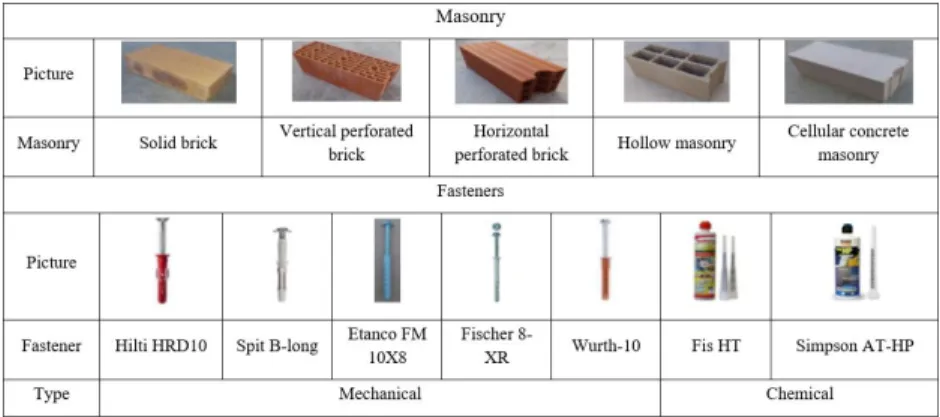
There are different ways to realize a cladding support according the building construction material: concrete walls, masonry walls and light material walls. The type of anchors used depends on the supports masonry and the load to bear. Table 1 gives an overview of the main mechanical (metal-plastic) and chemical anchors, and masonry supports [Boussa et al. 2014].
TABLE 1. Types of masonry and fasteners.
The failure modes of an anchor can affect either the anchorage system, or the block [Meyer et al. 2001]. Under tension loads, the most frequent failure mode is by pullout of the drilled hole with or without the mortar. In perforated blocks, the mortar plugs in the cavities of the unit can also be sheared off. A shear failure of masonry mortar can also occur by splitting, breakout or pulling out of the block. Under shear loading
[
Welz 2008], the most common failure mechanism in the anchorage itself is the steel failure of the anchor rod. The block can also be split, fail by local cracking (in front of the anchor or at the back), pullout of the bond at the edge of the masonry. In France, the anchor group of the French association of construction products and equipment (CISMA) recommended a methodology (Figure 1) to calculate the characteristic resistance value 𝑅𝑘,𝑠𝑡𝑎𝑡𝑖𝑐under static loads from in-situ tests [CISMA 2013].
III. EXPERIMENTAL DATA BASE
Among the numerous experimental studies (Eligehausen et al. 2006; Fushs et al., 1995, Delhomme et al, 2018), static and cyclic tests were carried out by the CSTB on 9 pairs of fastener/masonry support [Boussa et al. 2014]. These 9 pairs are composed of 5 different supports and 7 different fasteners (2 chemical and 5 mechanical anchors). For each pair, 20 tests were performed: 5 static tension tests, 5 cyclic tension tests, 5 static shear tests and 5 cyclic shear tests. The resistance was defined as the maximum load measured. The mean static tension and shear resistances, respectively NStatic and VStatic, and the relative variations (standard deviation divided by
RUGC 2020 AJCE, vol. 38 (1)
39 the mean) were calculated from 5 identical tests. In the shear and tension cycling tests, the cyclic loading was followed by a static residual loading until the failure. The tests were conducted in displacement control. The tension experimental setup consisted of a hydraulic actuator (50 kN capacity and 100 mm stroke). Concerning the shear tests, the hydraulic actuator (400 kN capacity and 100 mm stroke) was connected to a steel frame to transmit the loads to the anchor [Boussa et al. 2014].
IV. STATISTICAL ANALYSIS
Starting from the CSTB tests, a statistical analysis was performed in order to calculate the standard deviation and the characteristic value of each couple anchor/masonry support.For each resistance a characteristic value was calculated with a 5 % probability of non-exceedance and a confidence of 90 %. The results show that a normal distribution provides some negative characteristic resistances due to the scattering of the results inducing a high standard deviation. To reduce the standard deviation, the closest maximum loads obtained with only 4 tests, and then 3 tests, were kept. Some characteristic resistances obtained were still negative. Consequently, a log normal distribution according to [EC0 2003] was used to avoid this issue and enforce positive characteristic resistances.
V. SEISMIC SAFETY FACTOR AND SEISMIC DESIGN RESISTANCE
In this part of study, a methodology of calculation of anchors under seismic load will be defined by an analogy with the static methodology. The design value is defined as:
The seismic design resistance (Eq. 1) is calculated from the static characteristic resistance:
𝑅𝑑,𝑠𝑖𝑠=
𝑅𝑘,𝑠𝑡𝑎𝑡𝑖𝑐
𝛾𝑚 𝛾𝑠𝑖𝑠 (1)
where 𝑅𝑘,𝑠𝑡𝑎𝑡𝑖𝑐 is the characteristic static resistance, 𝛾𝑠𝑖𝑠 is a partial safety factor for seismic design and 𝛾𝑚 is a partial safety factor for the material defined in ATE. Generally, for use in masonry 𝛾𝑚=2.5 [ETAG 020 2012] [ETAG 029 2013].
The partial safety factor for seismic design 𝛾𝑠𝑖𝑠 is given in Eq. 2: 𝛾𝑠𝑖𝑠=
𝑚𝑖𝑛(𝑅𝑘,𝑖𝑛−𝑠𝑖𝑡𝑢,𝑅𝑘,5% 𝑠𝑡𝑎𝑡𝑖𝑐)
𝑅𝑘,5% 𝑐𝑦𝑐𝑙𝑖𝑐 (2)
where 𝑅𝑘,5% 𝑠𝑡𝑎𝑡𝑖𝑐 𝑎𝑛𝑑 𝑅𝑘,5% 𝑐𝑦𝑐𝑙𝑖𝑐 are the static and cyclic characteristic strengths with a fractile of 5%, respectively.
The envelope seismic safety factor sis for hollow and solid masonries from tension and shear tests
are 1.75 and 0.8, respectively. To simplify,sis equals to 1.75 is considered for all masonry supports.
Finally, the methodology to calculate the anchors under seismic loads is given in Figure 1. VI. CONCLUSION
In this research, CSTB tests database was the base of a statistical analysis in order to calculate the characteristic resistances. Two approaches were considered, the first one with a normal distribution, but negative values were obtained due to the high dispersion obtained in the experiments. The use of a log normal distribution was an efficient method to reduce the dispersion and avoid negative characteristics resistances. Finally, a methodology is defined, with a 1.75
RUGC 2020 AJCE, vol. 38 (1)
40 masonry seismic safety factor to apply to the static in-situ strength. In this regard, the uncertainties associated to the uncontrolled characteristics of the masonry and the fasteners are properly accounted in the seismic design resistance.
FIGURE 1. Calculation methodology of seismic design resistance
VII. REFERENCES
Boussa H., Gabs A.,Pinoteu N., Tenue des fixations pour bardages dans les éléments maçonnés en domaine
sismique, 2014.
Bui T.T., Limam A. Out-of-plane behaviour of hollow concrete block masonry walls unstrengthened and
strengthened with CFRP composite, Composites Engineering, 2014, 67:527-542.
CISMA, recommandations pour la réalisation d’essais de chevilles sur site, 2013.
Delhomme F., Pallud B., Rouane N. Tightening Torque Influence on Pullout Behavior of Post-installed Expansion Anchors, 2018, KSCE Journal of Civil Engineering volume, 22:3931–3939, doi.org/10.1007/s12205-018-0930-9.
Eligehausen R., Mallee R., Solva J. F. Anchorage in Concrete Construction, 2006, Ernst & Sohn, Berlin, Germany.
EN 1990, Basis of structural design, 2003.
EOTA, ETAG 029., ETAG of Metal Injection Anchors for use in Masonry, 2013.
EOTA, ETAG020, ETAG of plastic anchors for multiple use in concrete and masonry for non-structural
applications, 2012.
Fushs W., Eligehausen R., Breen J. E., Concrete capacity design (CCD) approach for fastening to concrete, 1995, ACI Structural Journal, 92:73-94.
Hofmann J., Welz G., Load-bearing behaviour and characteristic load-bearing capacity of injection anchors in masonry, 2017, European journal of masonry, 21(6):369-384, 2017, doi:10.1002/dama.201700019
Meyer A., Pregartner T., Fastening in masonry, 2001, International Symposium on Connections between Steel
and Concrete, 836-846, Stuttgart, Germany.
Sutherland R.J.M., Brick and block masonry in engineering, Proceedings of the Institution of Civil Engineers, 1981, 70(1):31-63.
Welz G., Metal injection anchors in masonry under shear loading, 2008, 7th fib PhD Symposium, 39-49,
Stuttgart, Germany.
To avoid brick extraction [ETAG 020, 2012]