Development Procedure for Scrum Compliance: An i*
Driven Process Fragment
Yves Wautelet1 , Sara Shafiee2 , Samedi Heng3
1
KU Leuven, Belgium [email protected],
2
Danmarks Tekniske Universitet, Danmark [email protected]
3
Universit´e de Li`ege, Belgium [email protected]
Abstract. Product Configuration Systems (PCS) are software applications sup-porting the design of products tailored to the individual desiderata of customers. PCS development does not follow the same procedure as traditional software: indeed, due to its nature, specific knowledge needs to be collected, a set of cus-tom engineering stages have thus been built-up. Within these stages, special re-quirements representation and design artifacts are used notably to deal with fea-tures inter-dependencies. More specifically, the Product Variant Master (PVM) has been specifically created for PCS knowledge representation while Class-Responsibility-Collaboration (CRC) cards and a UML Class Diagram are often indispensable for PCS object-oriented design. PCS development projects have gradually started to use agile methods like the Scrum. This paper presents a pro-cess fragment for conducting PCS development projects with Scrum; it overviews how the development team of a specific organization adapted the agile process to the PCS context. This process fragment has indeed been built on the basis of practitioners knowledge collected through 5 qualitative interviews (inductive approach) and exhaustively depict the activities performed by the team on PCS development projects of various size and context. Because of the possibility to represent social (role) dependencies, the fragment is visually represented using an i* Strategic Rationale Diagram. The main contribution of the paper is the frag-ment itself, it is intended to be dynamically used as an initial guidance for PCS development teams willing to conduct projects using Scrum; it can be tailored to any project/sprint and enriched at will.
Keywords: Product Configuration Systems, Agile Development, Scrum, DevOps, i-star, Feature Dependencies.
1
Introduction
A Product Configuration Systems (PCS) is a software-based system to support config-uring a product at will (automatically or on the basis of user input) to match the cus-tomers’ needs while satisfying technical constraints. Often the amount of possible con-figurations is huge because it increases exponentially with the number of configurable
Fig. 1. Car Product Configuration System (from [25]).
parameters. Also, constraints are often numerous and complex to express requiring spe-cific modeling artifacts. PCS enable companies to propose alternatives to facilitate their sales and production processes by integrating information about the product’s features, structures, constraints, costs and prices. Using the PCS, the client can build the exact product he wishes and by the same time make the first step in its production process. Widely used in various industries, PCS can bring substantial benefits [12,13,26] such as shorter lead times for generating quotations, fewer errors, increased ability to meet customers requirements regarding product functionality, the use of fewer resources, op-timized product designs, less routine work and improved on-time delivery. A PCS can for example be developed for configuring a car; the customer buying a new car is then capable of selecting the type of body, the color, the type of engine, etc. (see Figure1).
PCS being first and foremost software systems, their development have followed the evolution in software development life cycles. At first they were developed using a (sequential) seven steps procedure (see [14]) executed in a waterfall fashion. Later on, the procedure has been integrated in the Rational Unified Process (RUP) [15] life cycle for iterative development. With the growing popularity of Scrum, the question of using agile development within PCS development has been raised. Several internal charac-teristics of PCS nevertheless induce that the adoption of Scrum in such developments need to be handled with care. Scrum essentially prioritizes sprints on the basis of the business value induced by the development of user stories [31]. The latter are filling the so-called Product Backlog. Because of the high amount of dependencies among the configurable features in the product supported by the PCS, sprints cannot be managed on the basis of user stories exclusively. Indeed, more knowledge is required in order to ensure that constraints are handled adequately; this has an impact on the prioritization of developments. In other words, the constraints from the features’ dependencies induce that the sprints’ content cannot be driven by value only. Also, because of the complexity in the production process resulting from virtually infinite product configuration choices, domain experts (among which production engineers) constantly need to be consulted in the building and the validation of the PCS. Also, documentation on the state of the PCS needs to be produced and kept up-to-date to ensure all of the possible configurations are
supported and non-supported configurations are prescribed. Finally, short time release integration deliver significant added value, especially when new configurations of the product are made possible/available or existing configurations should be updated. Also, when new configurations need to be tested on small customers groups, immediate (even if they are partial) deployments have proven to be of value (because they allow to im-mediately attract customers and constitute life-sized evaluation environment). For these reasons and because they often need to be integrated in a broader software ecosystem, members of the operation team are involved in the execution of each sprint. This is in line with the DevOps [2] approach.
The aim of the research is to depict how the Scrum process has been adopted in a large organization specialized in the such developments. Due to the proven benefits in general software development, the adoption of Scrum has been, into the case organiza-tion, pushed by the top-management more than 3 years ago. Through a set of interviews, we aimed to understand what are the current activities and practices performed into a PCS development project conducted with Scrum. More specifically, we are interested in how the organization manages the elements identified in the previous section. On the basis of the data collected through interviews, we have built a process fragment. The latter is, with respect to the case organization, exhaustive (it depicts all of the activities) but not exclusive (not all of these activities are necessarily performed in each project and other activities can be added if found relevant). The process fragment is expressed with i* (i-star) [32] in order to highlight the social dependencies between the involved roles. The process fragment itself constitutes main contribution of the paper and can be used as a reference for PCS development professionals willing to conduct projects using Scrum. We nevertheless do not consider it as a fixed scientific truth but rather as a first reference that can be further used, tailored and validated by other PCS development teams and/or cases.
2
Theoretical Background
2.1 PCS Projects Specifics
There are enough differences between general software development projects and PCS ones for studying the impact of agile adoption in this specific field.
First of all, knowledge complexity and the possible extensions of PCS make the project scoping determinant [24]. This is done by identifying the requirements, evalu-ating the time and budget, and prioritizing the different products and functions. In PCS projects, goals and stakeholders requirements are mostly determined in the first steps because of the complexity and dependencies found in the product’s features, the range of involved stakeholders (from end-users desiderata to production specialists determin-ing the possible combinations), and other functional and non-functional requirements.
Secondly, because of the differences in the nature of the knowledge to be repre-sented, PCS are formalized, combined, modeled and communicated differently than in general software development projects. The knowledge modeled in PCS is indeed ex-tensive and has to be continually validated by domain experts and production specialists [25]. Strong communication between the PCS development team and these experts is thus vital. Without proper validation, very minor misunderstandings could lead to sig-nificant errors in the calculations and outputs.
Thirdly, clear and comprehensive documentation of the developed PCS has to be produced and needs to be understandable by all stakeholders in a non-technical lan-guage [11]. Also, PCS often need to be integrated in a complex software ecosystem; this requires propagation of related knowledge. In addition, frequent changes/updates in the supported product(s) requires continuous updates and maintenance [6].
Because of the aforementioned elements, PCS require the development of specific artifacts (see Section2.2) furnishing the data/information required by the PCS develop-ment team to perform its activities properly. The smooth integration of these artifacts into a Scrum-based project is addressed by the process fragment.
2.2 Product Configuration Systems, the Traditional Center Product Modeling Procedure
Hvam et al. [14] propose the Center Product Modeling (CPM) procedure for PCS de-velopment; the latter consists of seven stages called phases in the initial version to be executed in a waterfall fashion. These phases are to be mapped into disciplines fol-lowing the terminology of the RUP when integrated in the latter life cycle4. Several
extensions of CPM have been proposed (2001) (2003) (2006) (2008) over the years. The different stages of the CPM framework include (1) development of the specification processes, (2) analysis of the product range, (3) oriented modeling, (4) object-oriented design, (5) programming of the PCS, (6) plan for implementation, and finally (7) plan for maintenance and further development. For each of the stages artifacts are defined in order to represent/document relevant knowledge to fulfill the stage. Among those, we are particularly interested in the Product Variant Master (PVM) and Class-Responsibility-Collaboration(CRC) cards because these allow to represent constraints and dependencies in PCS knowledge representation.
The terminology used into the CPM framework is not entirely aligned with the ter-minology commonly used in Software Engineering (SE). Indeed, what is refereed to as Programmingin [14] is what SE generally refers to as Implementation (i.e., the phys-ical coding of the product using a programming language). Similarly, what is refereed to as Implementation in [14] is known as Deployment in SE. In the rest of this paper we adopt the terminology of general SE so that we use Implementation for the coding of the solution; the Deployment stage is outside the scope of the process fragment that we introduce in this paper so we do not refer to it later on.
2.3 Artifacts Traditionally Required in Product Configuration Systems Development Projects
The Product Variant Master To obtain an overall view of the products in the CPM framework, the product range is drawn up in a PVM to represent the phenomenon model [14]. The PVM consists of two structures, which are the part-of structure and the kind-of structure. The part-of structure represents the parts that appear in the entire product family. The classes are defined as object classes which include the name of the class, de-scription, attributes and constraints. The kind-of structure describes the different vari-ants the individual parts can have. Furthermore, the PVM contains a description of the
4The phases in RUP are indeed groups of iterations which are opposed to the stages of [14] that
Fig. 2. Structure of the PVM regarding part-of and kind-of structure (adjusted from [10]).
most important connections between parts, i.e., the rules for how parts are permitted to be combined. To preserve the overview of the PVM, CRC cards are associated with the PVM to describe the individual parts in more detail (see hereunder). The PVM rep-resents knowledge from different domains, which include customers, engineering and part/production view [10]. The causal connection can then be drawn between the views to identify complexity and non-value adding variety in the product range. The PVM is very important for scoping the project. It indeed determines what components are part of the PCS and what are not, the level of granularity and the modularization. All of the theoretical possibilities of product customization are not necessarily included due to complexity and economic reasons. Figure2shows an illustrative example of the PVM. The Class Diagram In the CPM framework, the UML class diagram [20] is used to represent the information model. Its individual classes are defined from the PVM using transformation rules. Aggregation and association structures are used for relationships between objects. The aggregation structure corresponds to the part-of structure in the PVM. The association structure is used if objects are associated with each other. Mul-tiplicities can be used with the aggregation and association structures to represent the number of sub-parts needed to make a super-part [14]. Generalization and package structures describe relationships between classes. The generalization structure corre-sponds to the kind-of structure in the PVM. Forward engineering rules allow to generate a class diagram directly from the PVM structure (see [14]).
Class-Responsibility-Collaboration Cards The CRC cards, which are associated with both the PVM and the class diagram, describe the classes in more detail. The CRC card was first proposed as a way to teach object-oriented thinking. Later, they were devel-oped for use in PCS projects, where they describe the individual object classes of the PVM and the class diagram in more details [14]. In other words, the CRC card defines the class, including the class name and its possible place in the hierarchy, together with a date and the name of the person responsible for the class. Also, the class task (re-sponsibility), the class attributes and methods, and with which classes it collaborates (collaboration) is given. Furthermore, a sketch of the product part represented by the class is included. The purpose of the CRC cards is to document detailed knowledge about the attributes and methods for the individual object classes and to describe the
classes mutual relationships. The CRC cards serve as documentation for both domain experts and system developers.
3
Research Method and Process Fragment Validation
In order to gather specific knowledge on how PCS teams apply Scrum in practice and build a process fragment, we proceeded through different stages.
First, the research team – composed of two specialists of the Scrum process into general software development projects and one specialist into Scrum and PCS devel-opment – made a preliminary brainstorming session to identify what elements are typi-cally needed in PCS development and potentially poorly supported by Scrum. A general presentation of Scrum was made, for each point, the adequacy for PCS developments was discussed. This allowed to build-up a series of questions. The first one asks for a very general description of all of the activities, the next ones result from the specifics discussed by the research team. This leads to the following list of questions:
– Describe all the activities that you are doing during a typical sprint;
– How do you gather domain knowledge? After initial start is it frequent to ask for clarifications? Who is the interface to obtain these then?
– Do you systematically need an evaluation of the AS-IS situation? What is the trigger to start with the modeling of the TO-BE situation?
– What are the models, tools to represent the (software/PCS) problem and solution? – Do systematically need the PVM and CRC cards in addition to User Stories to
depict the structure and functions of the PCS? Could User Stories be sufficient? Could you avoid using User Stories in a Scrum project?
– Do you use a class diagram to model the (PCS) Object Oriented application? What are your preferred sources of documentation (e.g., interviews, technical documents, workflows, etc.) to build it?
– How do you proceed with the testing of the output in a sprint? How do you select the end-users to be part of tests?
– How do you cascade/incorporate the feedback of users in the deliverable of the next sprints?
– How do you prioritize the developments for the next sprint? How do you manage the product’s features dependencies? Who sets the priorities and on what basis? – How do you manage the deployment of the PCS release? Is the release put in
pro-duction at the end of each sprint or is it included into a propro-duction backlog? Second, five qualitative interviews of members of a PCS development team (work-ing within a s(work-ingle organization) have been conducted. The interview process involved people that have been playing all of the different roles of a Scrum team in the studied organization. The latter team has more than ten years of experience in PCS development with both the RUP and Scrum. In that company, since the 3 last years, RUP has never-theless been totally abandoned to exclusively focus on Scrum. The interviews consisted in the open set of questions that has been depicted above.
Third, the qualitative data collected during the interviews was analyzed using concept-driven coding [7] leading to build a first version of the process fragment. It required
crossing all the information (and more specifically the project management and engi-neering related concepts) retrieved from the interviews. When there were ambiguities, they were discussed with a member of the research team that has been Scrum master in PCS projects for more than 6 years. The Scrum-based PCS development approach has been formalized using the process fragment concepts of [23] and graphically repre-sented in i* in the same fashion as in [30]. The choice of i* has been made because it highlights the social dependencies between the actors/roles but is not sequential. We in-deed did not want to document a sequence of activities in the process fragment because we observed that there is a high variability in their sequence and/or parallelism from project to project. This implicitly also shows the flexibility in the adoption of the pro-cess fragment by a new development team. Multiple activities can indeed be performed at the same time, some activities can be omitted, some others added and the sequence can be chosen in function of the field requirements/constraints. Workflow-based nota-tions that are more directive in terms of sequence, do not highlight social dependencies and are less tailorable/customizable and thus less relevant; the i* notation better allows to deal with the variability in the activities’ execution and selection.
Fourth, the “candidate” version of the process fragment built in the former stage has been presented to the practitioners involved in the interview stage (acting as a focus group) within the context of a workshop. The latter was meant to serve as an evaluation/-validation for the “candidate” process fragment. Concretely the process fragment and its notation were presented and explained followed by a group discussion on the accuracy, correctness and completeness. Their feedback/comments/ideas have been collected and the final version of the process fragment has been built; this version is the one presented in this paper (see Section4). The activities included in the process fragment vary from project to project and more specifically from sprint to sprint essentially in function of the PCS’s complexity, size and the desiderata of the development team. This final ver-sion is exhaustive meaning that it includes all of the possible activities reported by the development team. It is meant to be tailored to each project sprint. Activities can be selected dynamically in function of the scope and needs; new activities can also be added if required/found relevant by the adopting team. The process fragment is thus not prescriptive but rather customizable in function of the sprint’s context.
4
The Software Process Fragment
Table1documents all of the process fragment elements defined in Seidita et al. [23] that are instantiated onto our contribution.
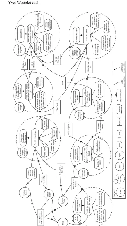
To graphically represent the process fragment’s elements, we use an i* Strategic Rationale (SR) diagram of Figure3. For clarity, we insist that, in a same project, each of the Roles can be played by several individuals and a same individual can also play different Roles. Moreover, the Scrum Master role is not part of the process fragment because its responsibilities and activities are generic in Scrum; we here focus on the aspects that are (PCS-)project related in the studied organization.
Specifically, because of the arrows present in the i* representation, the process frag-ment may seem to be directed, sequential and highly structured. The arrows neverthe-less only represent dependencies between the involved roles and do not prescribe the sequence of execution of activities. Similarly, it presents all of the activities that have
D o m a in E xp e rt C R C C a rd B u ld t h e I T syst e m Im p le m e n t P C S S yst e m a n d G e n e ra te O u tp u t Co d in g o f a ll th e n e e d e d o u tp u ts P C S S o ft w a re R e le a se P C S S yst e m Im p le m e n ta ti o n F e e d b a ck o n S o ft w a re r e le a se R e fi n e d U se r S to ry S e t R e m o ve re d u n d a n t re q u ir e m e n ts U se r S to ry m a p p in g S co p in g t h e p ro je ct B u ild th e P V M E st a b lish t h e l in k b e tw e e n p ro d u ct s va ri a b le s a n d co m p o n a n ts Id e n ti fy N ice -to -h a ve R e q u ir e m e n ts P ro vi d e t h e N e e d e d D a ta b a se s D e fi n e t h e U I D e te rm in e S ta ke h o ld e rs’ R e q u ir e m e n ts P ro vi d e K n o w le d g e D e fi n e t h e D e si re d O u tp u t P V M U se r S to ri e s S e t E n su re t h e co n si st a n cy , d e p e n d e n cy a n d h ie ra rch y o f U S D o m a in K n o w le d g e M e a su re t h e b u si n e ss va lu e s A n a lyz e P C S -b a se d B u si n e ss P ro ce ss B u ild A S -I S p ro ce ss fl o w ch a rt a n d b u si n e ss va lu e s E st a b ish a p ro p e r u n d e rst a n d in g f ro m t h e cu rr e n t te ch n ica l a n d b u si n e ss p ro ce ss P ro p o se t h e fu tu re S ce n a ri o s D e fi n e P C S B u ild T O -B E p ro ce ss fl o w ch a rt a n d p o te n ti a l S ce n a ri o s A sse s th e p ro p o e se d S ce n a ri o s a n d r e la te d TO -B E p ro ce sse s C h o o se t h e b e st S ce n a ri o B u si n e ss C a se AS -I S F lo w ch a rt TO -B E F lo w ch a rt D e fi n e U I a n d sys te m a rch it e ct u re A rch it e ct u re a n d D e si g n O b je ct -O ri e n te d A p p li ca ti o n B u ild t h e o b je ct -o ri e n te d d e si g n O b je ct o ri e n te d d e si g n L e g e n d : C la ss D ia g ra m S yst e m a rch it e ct u ra l d e si g n Id e n ti fy m issi n g re q u ir e m e n ts R e ci e ve t h e re q u ir e d i n p u ts a n d l im it t h e so lu ti o n sp a ce P ro vi d e t h e i n p u ts a n d o u tp u ts fo r th e u se rs G e n e ra te a ll th e n e e d e d o u tp u ts In te ra ct io n w it h u se r P C S S yst e m A ct o r A ct o r B o u n d a ry G o a l T a sk R e so u rce S o ft g o a l D e p e n d e n cy L in k A N D d e co m p o si ti o n M e a n s -E n d d e co m p o si ti o n A g e n t P ro vi d e p ro d u ct / p ro ce ss kn o w le d g e R o le U se r P ro d u ct O w n e r S yst e m T e st e r B u si n e ss P ro je ct M a n a g e r B u si n e ss A n a lyst R e q u ir e m e n t E n g in e e r S o ft w a re P ro je ct M a n a g e r S o ft w a re D e si g n e r S o ft w a re D e ve lo p e r
Table 1. Instantiation of our Process Fragment.
Element Definition (from [23]) Instantiation to our process fragment i* Represen-tation Design
Pro-cess
Design process from which the fragment has been extracted.
The Scrum Agile Method. N/A
Phase A specification of the fragment position in the design workflow. Usually referring to a taxonomy.
Determine Stakeholders Requirements, Process Analysis, Product Analysis, Manage Product Back-log, Object oriented Analysis and Design, PCS Sys-tem Implementation, PCS SysSys-tem Release Deploy-ment, Test.
Goal
Goal The process-oriented objective of the fragment.
The integration of PCS development in Scrum. N/A Activity A portion of work assignable to a
per-former (role).
Gather Knowledge, Build AS-IS process flowchart and business values, Define PCS, Plan Release, Architecture and Design Object-Oriented Applica-tion, Implement PCS System and Generate Output, Test Integration of Release, Test Release.
Task
Work Prod-uct
The resulting product of the work done in the fragment; it can be realized in differ-ent ways also depending on the specific adopted notation.
Business Case, AS-IS Flowcharts, TO-BE Flowcharts, User Stories Set, Class-Responsibility-Collaboration Cards, Product Variant Master, User Stories for Sprint, Class Diagram, System architectural design, PCS Software Executable Release, Refined User Story Set.
Resource
Role The stakeholder performing the work in the process and responsible of producing a work product (or part of it).
Domain Expert, Product Owner, Business Analyst, Requirements Engineer, Software Designer, Soft-ware Developer, Infrastructure Engineer, System Tester, User.
Role
Description It is the textual and pictorial description of the fragment; it provides a bird-eye on the whole process the fragments come from and the fragment overview in terms of tasks to be performed, roles and work product kind to be delivered.
The i* Process Model of Figure3. A Strategic Rationale Diagram
Composition Guideline
A set of guidelines for assembling/com-posing the fragments with others.
The transformation of the PVM to a class diagram as presented in [14]. The transformation rules from a PVM to a User Story Set.
N/A
been reported as useful in the development of a PCS using Scrum but not all of them necessarily need to be performed in a specific sprint nor Scrum project. If used as a ref-erence, the process fragment can be tailored at will to each specific sprint into a project. We distinguish several types of stakeholders having various goals and expectations, i.e.: – The Product Owner (PO) Role is a senior manager that is mainly in charge of de-veloping a vision of the PCS that needs to be built and propagate that vision over the development team; it is a key stakeholder of the project. He does not provide a detailed specification of the PCS but rather a coarse-grained vision of how the PCS will be developed and integrated in the software ecosystem. The first process fragment Activities are performed by this role. These are performed in the context of the Determine Stakeholders Requirements Phase which is represented as an i* Goal in Figure3. A means-end decomposition then allows to refine the i* Goal representing the Phase. Indeed, to fulfill this i* Goal, the PO Role performs the Activity Gather Knowledge. In itself, the latter Activity requires a set of other Ac-tivities to be achieved (as shown through the decompositions in Figure3). These are Define the Desired Output, Provide the Needed Databases and Identify Nice to-have Requirements; the output of these Activities is compiled into the Business CaseWork Product). In addition, the PO Role also performs activities in the
con-text of the Manage Product Backlog Phase which is represented as an i* Goal. A means-end decomposition then allows to refine the i* Goal representing the Phase. Indeed, to fulfill this i* Goal, the PO Role performs the Activity Plan Release [21]. The latter Activity allows to select a specific sub-set of User Stories (from the entire set of User Stories) to be developed/prototyped within the next Sprint. This allows to build the User Stories for Sprint Work Product used by the Software Designer Role to fulfill the Architecture and Design Object-Oriented Application Activity; – The Domain Expert Role is played by all of the experts of the organizations’
busi-ness processes and/or product and is thus in charge of participating to the Provide Domain KnowledgeActivity fulfillment;
– The Business Analyst Role performs is activities in the context of the Process Anal-ysisPhase which is represented as an i* Goal in Figure3. A means-end decom-position then allows to refine the i* Goal representing the Phase. Indeed, to fulfill this i* Goal, the Business Analyst Role performs the Activity Build AS-IS process flowchart and business values. In itself, the latter Activity requires a set of other Ac-tivities to be achieved (as shown through the decompositions in Figure3). These are Establish a proper understanding from the current technical and business process, and Measure the business values; the output of these Activities is compiled into the AS-IS Flowcharts Work Product). In the particular domain of PCS, we indeed proceed through an evaluation of the AS-IS business processes before defining the PCS. This practice is adopted by agile teams as well;
– The Requirements Engineer Role performs activities in the context of the Product AnalysisPhase which is represented as an i* Goal in Figure3. A means-end de-composition then allows to refine the i* Goal representing the Phase. Indeed, to fulfill this i* Goal, the Requirements Engineer Role performs the Activity Define PCS. In itself, the latter Activity requires two Activities to be achieved. These are Build TO-BE process flowchart and potential Scenariosand Build the Product Vari-ant Master and CRC Cards. Both Activities requires a set of other Activities to be achieved (as shown through the decompositions in Figure3). More specifically:
• To achieve the Build TO-BE process flowchart and potential Scenarios Activity, one need to perform the Activities Propose the future Scenarios, Asses the pro-posed Scenarios and related TO-BE processes, Identify missing requirements and Choose the best Scenario. This allows to build the TO-BE Flowcharts Work Product later used by the Software Designer Role to fulfill the Archi-tecture and Design Object-Oriented ApplicationActivity;
• To achieve the Build the Product Variant Master and CRC Cards Activity, one need to perform the Activities Establish the link between products variables and components, Remove redundant requirements and Ensure the consistency, dependency and hierarchy of User Stories. This allows to build the CRC Cards as well as the PVM Work Products used by the Software Designer Role to fulfill the Architecture and Design Object-Oriented Application Activity. Also the output of these Activities allow to build the User Story Set Work Product later used by the PO Role to fulfill the User Story mapping Activity.
– The Software Designer Role is in charge of transforming the specifications into a software architecture and design. He performs his activities in the context of the Object-Oriented Analysis and DesignPhase which is represented as an i* Goal in
Figure3. A means-end decomposition then allows to refine the i* Goal representing the Phase. Indeed, to fulfill this i* Goal, the Software Designer Role performs the Activity Architecture and Design Object-Oriented Application. The latter Activity allows to design the application. In itself, the latter Activity requires a set of other Activities to be achieved (as shown through the decompositions in Figure3). These are Define User Interface, Build system architecture and Build the object-oriented design. This allows to build the Class Diagram and the System architectural design Work Products used by the Software Developper Role to fulfill the Implement PCS System and Generate OutputActivity;
– The Software Developer Role is in charge of transforming the software architecture and design into an executable PCS. He performs his activities in the context of the PCS System Release ImplementationPhase which is represented as an i* Goal in Figure3. A means-end decomposition then allows to refine the i* Goal representing the Phase. Indeed, to fulfill this i* Goal, the Software Developer Role performs the Activity Implement PCS System and Generate Output. The latter Activity allows to build an executable release ready to be tested. In itself, the latter Activity requires a set of other Activities to be achieved (as shown through the decompositions in Figure3). These are Build the IT system and Coding of all the needed outputs. This allows to build the PCS Software Executable Release Work Product used by the System TesterRole to fulfill the Test Release Activity;
– The Infrastructure Engineer Role is in charge of ensuring that the release of the PCS built during the Sprint can be put in production through a smooth integration in the software infrastructure. He performs his activities in the context of the PCS System Release DeploymentPhase which is represented as an i* Goal in Figure 3. A means-end decomposition then allows to refine the i* Goal representing the Phase. Indeed, to fulfill this i* Goal, the Infrastructure Engineer Role performs the Activity Test Integration of Release. In itself, the latter Activity requires a set of other Activities to be achieved (as shown through the decompositions in Figure 3). These are Perform Infrastructure Compatibility Testing for New Release and Perform Load Testing for New Release. This allows to build the PCS Software Ex-ecutable ReleaseWork Product used by the System Tester Role to fulfill the Test ReleaseActivity and the Refined User Story Set Work Product used by the Require-ments Engineer Role to fulfill the Build TO-BE process flowchart and potential ScenariosActivity;
– The System Tester Role is in charge of testing the developed PCS release. He per-forms his activities in the context of the Testing Phase which is represented as an i* Goal in Figure3. A means-end decomposition then allows to refine the i* Goal representing the Phase. Indeed, to fulfill this i* Goal, the System Tester Role per-forms the Activity Test Release. The latter Activity allows to evaluate the output of the Sprint; for this the System Tester Role depends on the (end) User Role for fulfilling the Provide Feedback on Software Release Activity. This allows to build the Refined User Story Set Work Product used by the Requirements Engineer Role to fulfill the Define PCS Activity. We here refer to refining the business processes and the PCS analysis for the next Sprint;
– The (end) User Role uses the PCS and is thus in charge of participating to the Feedback on the Software ReleaseActivity fulfillment.
5
Discussion: Requirements Representation and Backlog
Management within Scrum
Scrum traditionally manages its backlog on the basis of user stories. User stories written for the development of a PCS nevertheless requires to be accompanied with product structural details. To be able to create the configuration solution space for a specific product, one needs to be aware of the whole product architecture, the sequence (and importance) of the selection (which feature impacts others and should be chosen first), the constraints on product components (e.g., if the customer can order a car with 6 doors the whole product should be adjustable), etc. Consequently, the user stories are most often completed with a series of constraints. For example, the user story As an online customer, I want to be able to choose the size of engine so that I can choose my preferred car capacity, are accompanied with the scenario(s) Given motor size is valid, When it is chosen from “2, 2.3, 2.5 liter”. Then the: (i) Selection 2 is not valid is car has 4 doors; (ii) Selection 2.5 is not valid if car is 2 doors.Since these constraints are difficult to express fully and efficiently in (structured) natural language, the PVM (with CRC cards) are used as a complementary documentation for the development team. Systematically these need to be built for any complex PCS development project and are consulted when filling the sprint backlog to ensure the constraints and dependencies are respected. There is redundancy between the constraints found with the user stories and the PVM; user stories serve for quick reference and the PVM is used for formal support. In practice, in a PCS development project, the user stories drive the sprint backlog on the basis of their value but the the precedence constraints and dependencies lead to form groups of US that need to be implemented in the same release/sprint. In PCS, the prioritization of the user stories indeed depends on the structure of the product itself as well as the technical constraints. The product components which are the major variables controlling the solution space need to be developed and positioned at the beginning of PCS project. Moreover, from the technical perspective, the main attributes cannot be positioned after the minor ones as they should be located in a higher level of abstraction to be able to control the minor attributes range. For example, if we want to write the user stories to develop a PCS for a car, first of all, we should know about the product and which components have a higher priority; e.g., we cannot go to the details of the leather in the interior design before determining the main elements of the car. This has a significant impact on the management of the software process; these precedence constraints are the main driver of the release delivery in every Scrum-based PCS project. Setting-up precedence/dependency constraints and ensuring they are respected is currently done manually in the studied organization. Also, no tool support is ensuring traceability between the user stories and the PVM requiring substantial domain knowl-edge to consistently fill the product/sprint backlogs. A Computer Aided Software En-gineering (CASE) tool for backlog management is under development; it ensures trace-ability and consistency between the so-called user story view and PVM view. Based on the formal linkage between user stories and PVM parts, the tool automatically validates that all the constraints are respected when a sprint backlog is filled.
6
Towards a Revised Process Pattern for Product Configuration
Systems Development and Threats to Validity
As shown process in the fragment, PCS development practices with Scrum subse-quently evolved from the classical CPM procedure of [14]. Analysis practices remain rather aligned with that framework; indeed, in our process fragment we start with the Process Analysisincluding the evaluation of the situation AS-IS and the Product Anal-ysisthat includes the evaluation of the TO-BE processes and a first specification of the PCS. This remains aligned with the first and second stages of the traditional PCS devel-opment framework. At design stage we nevertheless have a significant difference with the latter framework. Our process fragment indeed considers Object Oriented Analysis and Designin one stage. The main reason that can be evoked here is that agile practices focus on fast development and do not advice to spend a lot of time on software architec-ture and design but rather prescribes to re-factor the architecarchitec-ture later on in the devel-opment if required. The Implementation stage of our process fragment corresponds to the Programming stage of the classical PCS development framework. Also, no explicit project management is evoked in the framework from [14]; in the proposed process fragment, the content of the Sprints are defined by the PO in the Manage Product Back-logstage. Finally, for an optimal integration of the PCS into the software ecosystem, practitioners include operators at the implementation stage. This allows to include the deployment constraints into the release development to ensure the PCS a smooth inte-gration; this is a genuine practice not present in the CPM procedure.
Even if we do not strictly speaking conduct an experiment nor ask specific research questions so we do not draw formal conclusions (statistical or otherwise), we include some threats to validity related to the data collection that might lead to errors and haz-ards into the process fragment that we have presented.
With respect to the construct validity, the main threat is that interview questions are not interpreted by interviewees the way intended by the interviewers. To manage this, we conducted several interviews with people playing or having played each role. This allowed to collect multiple opinions on the same question/aspect so that the reliability on what we have inferred increases. Similarly, the process fragment has been validated with the interviewees in order to reduce the impact of this particular treat.
As far as the internal validity is concerned, the major threat is that answers from interviewees reflected their personal opinion(s) on how the organization should behave rather than how it empirically behaves. Also, the interviewees roles have an influence on the knowledge he/she has on the asked questions. To deal with this we also asked the same set of questions each relating to different area of knowledge to each of the interviewees. This allowed to have the answer of the specialists (the roles involved in specific activities we ask a question on) as well as the ones of people that are not performing the activities but interact with the people performing them. Consequently, we have a more credible global picture of the organizational behavior.
The treat to external validity is that the results may not be generalizable to other organizations than the one studied. This threat to validity should be taken very seriously. We have presented the whole contribution as the results of the modeling of a single or-ganization having experience on multiple projects. The process fragment has been made exhaustive meaning that it documents a set of practices that can or cannot be adopted in
a single project/sprint. It should of course be further extended/validated on the basis of interviews in other organizations but we aimed to have a first study here showing how a complex PCS development is managed with Scrum into a mature organization.
7
Related Work
To the best of our knowledge, no scientific study reported on the use of Scrum or any agile method in the context of PCS. Other studies have nevertheless been made where other artifacts were used for software analysis in combination with user stories be-cause of domain specifics (e.g., [29,27]). PCS and Software Product Line Engineering (SPLE) nevertheless do share common characteristics [17]. While PCS mainly support traditional engineering products (e.g., mechanical, electronic, etc.), software product families and SPLE are used in the engineering of software variants. These approaches all target to design new variants for a product family to meet customer requirements. To represent product knowledge, SPLE mostly uses feature models [16], a tree-like graph-ical model comparable to the PVM since it represents elements and their dependencies. Because of this similarity and the impact of this similarity on the management of the software development, we overview work relating SPLE and Agile Development (AD). By definition, SPLE and AD can be seen as water and oil; as opposed to AD, SPLE focuses on upfront design [4]. Several works have nevertheless been conducted to com-bine SPLE and AD (e.g., [5,9,8,18,19]). In SPLE, two engineering phases are existing, Domain Engineering (DE) relating the domain knowledge and Application Engineering (AE) relating the customer needs; AD could be applied in these two phases of SPLE. However, the adoption of AD in DE requires more effort than in AE [4] because of the features dependencies (represented in the features model and requiring upfront design). This issue can immediately be related to the one of building the PVM in PCS.
O’Leary et al. (2012) [19] developed an Agile Process model for Product Derivation (A-Pro-PD). The latter aims at minimizing upfront investments. It combines the core assets of SPLE such as feature models, architecture models, code artifacts with AD. PuLSE-I [3] proposes to adopt agile practices such as planning games and incremental design into Product Derivation. Diaz et al. (2014) [5] customize the Scrum process for SPLE. User stories are used for describing software product-line features; they are prioritized on the basis of business value and assigned to sprints. The research in [22] aims at aligning SPLE artifacts from Kunbang [1] with AD artifacts from Agilefant [28]. More specifically, they relate leaf features (not composed of other features) to a feature backlog itself composed of the product backlog. The feature backlog is thus composed through elements on the lowest granularity level and recomposed into the product backlog for iteration (sprint) management.
8
Conclusion
The specifics of PCS make them an interesting but complicated application domain for a software development based on agile methods. PCS constitute the primary interface with the customer so that they are user-centered systems requiring feedback and valida-tion to be aligned at best with their expectavalida-tions. In such a context, proceeding through sprints would turn out to be very beneficial. PCS are nevertheless narrowly tight with
the constraints inherent to the product they allow to customize so that there is less lati-tude in their development than in general software systems. Short releases immediately deployed allow testing the impact of new configurations on some particular customer sets to collect relevant sales data and efficiently support the production process.
This paper’s main contribution is a process fragment for PCS development using Scrum. The latter has been built on the basis of data gathered from a PCS development team having substantial experience in such developments; it has been made exhaustive to include all of the reported activities of the case organization and aligned with the knowledge, syntax and semantics of SE concepts found in literature. This allowed to build a first reference of a process fragment tailorable to any PCS development project and more particularly its sprints. As such, it does not constitute a unique truth/path-way to be adopted/used faithfully but rather a guidance to be dynamically tailored for each project/sprint in function of their specifics and the desiderata of the development team. It nevertheless constitutes a consistent whole that can be used as a starting point for PCS development teams willing to adopt Scrum, agile and some DevOps practices in their projects. Finally, the process fragment has to evolve by (i) the study of more settings where the application of an agile method has to deal with software with much dependencies and technical constraints and (ii) by its active application on case studies. More roles, activities, tasks and artifacts can of course be added but the process frag-ment needs to remain easy to use in order not to hamper the agility of the project. We point to the development of a CASE tool to support activity selection to dynamically tailor it to a specific project/sprint. This way variability in the roles, activities and work products when adopting the fragment can be actively supported.
References
1. Asikainen, T., M¨annist¨o, T., Soininen, T.: Kumbang: A domain ontology for modelling vari-ability in software product families. Advanced Engineering Informatics 21(1), 23–40 (2007) 2. Bass, L., Weber, I., Zhu, L.: DevOps: A software architect’s perspective. Addison-Wesley
Professional (2015)
3. Carbon, R., Lindvall, M., Muthig, D., Costa, P.: Integrating product line engineering and ag-ile methods: flexible design up-front vs. incremental design. In: 1st International Workshop on Agile Product Line Engineering (APLE’06), Maryland, USA (2006)
4. D´ıaz, J., P´erez, J., Alarc´on, P.P., Garbajosa, J.: Agile product line engineering – a systematic literature review. Software: Practice and experience 41(8), 921–941 (2011)
5. D´ıaz, J., P´erez, J., Garbajosa, J.: Agile product-line architecting in practice: A case study in smart grids. Information and Software Technology 56(7), 727–748 (2014)
6. Friedrich, G., Jannach, D., Stumptner, M., Zanker, M.: Knowledge engineering for configu-ration systems. Elsevier (2014)
7. Gibbs, G.R.: Thematic coding and categorizing. Analyzing qualitative data 703, 38–56 (2007)
8. Haidar, H., Kolp, M., Wautelet, Y.: An integrated requirements engineering framework for agile software product lines. In: Software Technologies - 13th International Conference, IC-SOFT 2018, Porto, Portugal, July 26-28, 2018, Revised Selected Papers. pp. 124–149 (2018) 9. Hanssen, G.K., Fægri, T.E.: Process fusion: An industrial case study on agile software
prod-uct line engineering. Journal of Systems and Software 81(6), 843–854 (2008)
10. Harlou, U.: Developing product families based on architectures. Department of Mechanical Engineering, Technical University of Denmark (2006)
11. Haug, A., Hvam, L.: The modelling techniques of a documentation system that supports the development and maintenance of product configuration systems. International Journal of Mass Customisation 2(1-2), 1–18 (2007)
12. Haug, A., Hvam, L., Mortensen, N.H.: The impact of product configurators on lead times in engineering-oriented companies. AI EDAM 25(2), 197–206 (2011)
13. Hvam, L., Haug, A., Mortensen, N.H., Thuesen, C.: Observed benefits from product config-uration systems. Int. J. of Ind. Eng.: Theory, Applications and Practice 20(5-6), 1–6 (2013) 14. Hvam, L., Mortensen, N.H., Riis, J.: Product customization. Springer (2008)
15. IBM: The Rational Unified Process, Version 7.0.1 (2007)
16. Kang, K.C., Cohen, S.G., Hess, J.A., Novak, W.E., Peterson, A.S.: Feature-oriented domain analysis (foda) feasibility study. Tech. rep., Carnegie-Mellon Univ Pittsburgh Pa Software Engineering Inst (1990)
17. M¨annist¨o, T., Soininen, T., Sulonen, R.: Product configuration view to software product fam-ilies. In: 10th International Workshop on Software Configuration Management (SCM-10), Toronto, Canada. pp. 14–15 (2001)
18. Noor, M.A., Rabiser, R., Gr¨unbacher, P.: Agile product line planning: A collaborative ap-proach and a case study. Journal of Systems and Software 81(6), 868–882 (2008)
19. O’Leary, P., McCaffery, F., Thiel, S., Richardson, I.: An agile process model for product derivation in software product line engineering. Journal of Software: Evolution and Process 24(5), 561–571 (2012)
20. OMG: Omg unified modeling language (omg uml). version 2.5. Tech. rep. (2015)
21. Patton, J., Economy, P.: User story mapping: discover the whole story, build the right product. ” O’Reilly Media, Inc.” (2014)
22. Raatikainen, M., Rautiainen, K., Myll¨arniemi, V., M¨annist¨o, T.: Integrating product family modeling with development management in agile methods. In: Proceedings of the 1st inter-national workshop on Software development governance. pp. 17–20. ACM (2008)
23. Seidita, V., Cossentino, M., Chella, A.: A proposal of process fragment definition and docu-mentation. In: European Workshop on Multi-Agent Systems. pp. 221–237. Springer (2011) 24. Shafiee, S., Hvam, L., Bonev, M.: Scoping a product configuration project for
engineer-to-order companies. International Journal of Industrial Eng. and Mgmt 5(4), 207–220 (2014) 25. Shafiee, S., Hvam, L., Haug, A., Dam, M., Kristj´ansd´ottir, K.: The documentation of product
configuration systems: A framework and an IT solution. Advanced Engineering Informatics 32, 163–175 (2017),https://doi.org/10.1016/j.aei.2017.02.004
26. Trentin, A., Perin, E., Forza, C.: Product configurator impact on product quality. International Journal of Production Economics 135(2), 850–859 (2012)
27. Trkman, M., Mendling, J., Trkman, P., Krisper, M.: Impact of the conceptual model’s rep-resentation format on identifying and understanding user stories. Information and Software Technology (2019)
28. V¨ah¨aniitty, J.: Do small software companies need portfolio management, too. In: Proceed-ings of the 13th International Product Development Management Conference (Milan, Italy, 2006). EIASM. pp. 1471–1486. Citeseer (2006)
29. Wautelet, Y., Heng, S., Hintea, D., Kolp, M., Poelmans, S.: Bridging user story sets with the use case model. In: Advances in Conceptual Modeling - ER 2016 Workshops. pp. 127–138 (2016)
30. Wautelet, Y., Heng, S., Kiv, S., Kolp, M.: User-story driven development of multi-agent systems: A process fragment for agile methods. Computer Languages, Systems & Structures 50, 159–176 (2017)
31. Wautelet, Y., Heng, S., Kolp, M., Mirbel, I.: Unifying and extending user story models. In: Proceedings of the 26th International Conference Advanced Information Systems Engineer-ing (CAiSE). LNCS, vol. 8484, pp. 211–225. SprEngineer-inger (2014)
32. Yu, E., Giorgini, P., Maiden, N., Mylopoulos, J.: Social Modeling for Requirements Engi-neering. MIT Press (2011)
![Fig. 1. Car Product Configuration System (from [25]).](https://thumb-eu.123doks.com/thumbv2/123doknet/6346246.167289/2.892.286.624.167.380/fig-car-product-configuration-system-from.webp)
![Fig. 2. Structure of the PVM regarding part-of and kind-of structure (adjusted from [10]).](https://thumb-eu.123doks.com/thumbv2/123doknet/6346246.167289/5.892.302.625.176.353/fig-structure-pvm-regarding-kind-structure-adjusted.webp)