HAL Id: hal-03182105
https://hal.archives-ouvertes.fr/hal-03182105
Submitted on 26 Mar 2021
HAL is a multi-disciplinary open access
archive for the deposit and dissemination of
sci-entific research documents, whether they are
pub-lished or not. The documents may come from
teaching and research institutions in France or
abroad, or from public or private research centers.
L’archive ouverte pluridisciplinaire HAL, est
destinée au dépôt et à la diffusion de documents
scientifiques de niveau recherche, publiés ou non,
émanant des établissements d’enseignement et de
recherche français ou étrangers, des laboratoires
publics ou privés.
Modelling the compaction of plastic particle packings
Saeid Nezamabadi, Mojtaba Ghadiri, Jean-Yves Delenne, Farhang Radjai
To cite this version:
Saeid Nezamabadi, Mojtaba Ghadiri, Jean-Yves Delenne, Farhang Radjai.
Modelling the
com-paction of plastic particle packings.
Computational Particle Mechanics, Springer Verlag, 2021,
�10.1007/s40571-021-00391-4�. �hal-03182105�
https://doi.org/10.1007/s40571-021-00391-4
Modelling the compaction of plastic particle packings
Saeid Nezamabadi1,2,3 · Mojtaba Ghadiri3· Jean-Yves Delenne2· Farhang Radjai1
Received: 24 August 2020 / Revised: 26 January 2021 / Accepted: 3 February 2021 © OWZ 2021
Abstract
Soft particle materials such as some pharmaceutical and food products are composed of particles that can undergo large deformations under low confining pressures without rupture. The rheological and textural properties of these materials are thus governed by both particle rearrangements and particle shape changes. For the simulation of soft particle materials, we present a numerical technique based on the material point method, allowing for large elasto-plastic particle deformations. Coupling the latter with the contact dynamics method makes it possible to deal with contact interactions between particles. We investigate the compaction of assemblies of elastic and plastic particles. For plastic deformations, it is observed that the applied stress needed to achieve high packing fraction is lower when plastic hardening is small. Moreover, predictive models, relating stress and packing fraction, are proposed for the compaction of elastic and plastic particles. These models fit well our simulation results. Furthermore, it is found that the evolution of the coordination number follows a power law as a function of the packing fraction beyond jamming point of hard particle packings.
Keywords Material point method · Contact dynamics · Granular materials · Powders · Plastic particles
1 Introduction
Compaction is one of the most important manufacturing processes of particulate materials, used in a number of industries, including food, pharmaceutical, chemical, pow-der metallurgy, ceramic and nuclear industries. This process transforms loose particulate materials into a compacted prod-uct with a higher packing fraction [1,2]. During the initial stage of compaction, particles can rearrange while keep-ing their initial shapes. Advanckeep-ing in compaction process, particles undergo large (elastic and/or plastic) deformations, which cause particle shape changes. The latter allows achiev-ing high packachiev-ing fractions, which considerably exceed the random close packing (RCP) limit.
In order to understand the compaction process better, it can be modelled using two main numerical techniques: (i) contin-uum approach, in which particulate materials are considered
B
Saeid Nezamabadi1 LMGC, CNRS, University of Montpellier, Montpellier,
France
2 IATE, INRAE, Montpellier SupAgro, University of
Montpellier, Montpellier, France
3 School of Chemical and Process Engineering, University of
Leeds, Leeds LS2 9JT, UK
as a continuum medium [3–5]; and (ii) discrete element modelling, in which the behaviour and interaction of individ-ual particles are taken into account [6,7]. The first method is based on defining macroscopic constitutive laws taking account of micro-dynamic information of particles. The dis-crete element method (DEM) is generally used in the context of the second approach. In DEM, particles are assumed to be slightly deformable through different contact theories such as the Hertz contact theory, which is only valid up to about 10% of strain. However, in the context of compaction process modelling, this assumption is too crude. For realistic simu-lation of compaction, it is hence primordial to combine a continuum representation of the particles, allowing for their deformation according to a prescribed constitutive model, with appropriate contact interactions between particles [8,9]. In this paper, our numerical approach is based on a parallel implicit material point method (MPM) in association with the contact dynamics (CD) method for the treatment of frictional contacts between particles [9–11]. Using this approach, we first study the behaviour of a single plastic particle subjected to axial strain. This method is then applied to the compaction simulation of a packing of plastic particles. The packing can reach high packing fractions beyond the “jamming” point by particle shape changes and still deform plastically. As we
shall see, the particle plastic behaviour affects the stress level and its evolution during compaction.
In the following, we first briefly introduce the numeri-cal approaches in Sect.2. Then, Sect. 3 is devoted to the behaviour of a single particle subjected to diametrical com-pression. We focus in Sect.4on the compaction process of packings of plastic particles. We conclude with a brief sum-mary of this work.
2 Methodology
In this section, our methodology based on the coupling of an implicit MPM formulation and the contact dynamics method is described briefly. This approach was introduced in the pre-vious works [9–11]. Here, we present its extension to plastic behaviour in the context of the infinitesimal strain theory.
We consider a domain Ω inRD, D being the domain
dimension, describing a continuum body. Its conservation of mass is described by the following continuity equation:
∂ρ(x, t)
∂t + ∇ (ρ(x, t) · v(x, t)) = 0 in Ω , (1) and the Cauchy form of conservation of linear momentum for this body is given by the equation:
∇ · σ (x, t) + b(x, t) = ρ(x, t) a(x, t) in Ω . (2) In the above equations, ρ(x, t), v(x, t), σ (x, t), b(x, t) and a(x, t) represent, respectively, material density, velocity, Cauchy stress tensor, body force and acceleration at position
x and time t.
The momentum relation (2) must be complemented with a constitutive relationship, which relates the Cauchy stress, σ, to the strain tensor, " ("= 12!∇u +t∇u", u being the
dis-placement field). Here, we consider a linear isotropic elastic material model and a rate-independent elasto-plastic model based on the bilinear isotropic hardening [12]. The latter uses the von Mises yield criteria coupled with an isotropic work hardening assumption. It is called bilinear because just two lines define the stress–strain curve with a transition point defined as the yield stress σy: one to describe the linear
elas-tic region with Young’s modulus, E, and another to the plaselas-tic with hardening modulus, H.
In MPM, the continuum body is discretised by a set of material points with fixed mass. According to the assump-tion of the fixed material point mass, the mass conservaassump-tion relation (1) is automatically satisfied. The MPM can be considered as a finite element method (FEM) with moving integration points (material points) that serve to compute the FEM integrals. The MPM discretises these integrals through a Dirac delta function. Hence, the weak form of the
momen-tum relation (2) in its discretised version can be written in the presence of contact interactions between several bodies, in the following form:
M anode(t)= fint(t)+ fext(t)+ fC(t) , (3) where anodeis the nodal acceleration, fCrepresents the nodal contact force (see below), and
M =
Np #
p=1
mpNp Lumped mass matrix,
fint= −
Np #
p=1
GpσpVp Internal force vector,
fext=
Np #
p=1
Npbp+ fS Sum of body forces and
surface tractions, fS.
In the above relations, mpand Vpare the mass and volume of
a material point p, and Npindicates the number of material
points. Npis the interpolation matrix (or the shape function
matrix) at the material point p. It relates the quantities asso-ciated with the material points (displacement, position, etc.) to nodal variables of the element to which the material point belongs. Gpis the gradient of the shape function Np.
Equation (3) is solved using an implicit MPM approach described in the previous work [10]. The nodal solutions are then projected onto the material points, allowing for updat-ing the information carried by these points. Note that the implementation of the plastic constitutive law in the implicit MPM approach is similar to the finite element method since the MPM can be considered as a minor modification of the classical FEM. It is also worth noting that here, the evolution of the material point volume Vpis considered to change from
time t to t+ %t as
Vp(t+ %t) = det(I + ∇uptt+%t)Vp(t), (4)
where uptt+%trepresents the displacement filed of the
mate-rial point p between the times t and t + %t and I is the second-order identity tensor. This evolution is based on the finite strain MPM formulation as defined by [11].
Finally, since our MPM formulation is used to deal with the soft particle systems, the nodal contact forces fCbetween deformable particles are computed using a multi-mesh con-tact algorithm coupling with the concon-tacts dynamics method. In the context of multi-mesh algorithm, each soft particle maps in its proper background mesh. A contact point at the interface between two particles may be treated by introduc-ing a common background mesh with the same type of grids for the transfer of nodal quantities from proper meshes to
0. 0.05 0.1 0.15 0 0.5 1 1.5 2 2.5 εyy σyy (M P a) Plastic H = 0 MPa Plastic H = 1 MPa Plastic H = 3 MPa Elastic
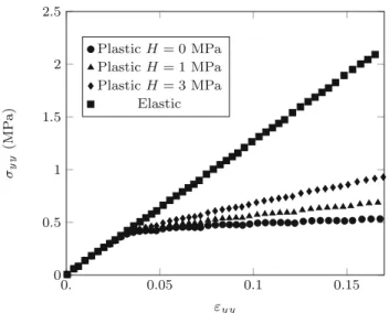
Fig. 1 Stress–strain diagrams for the single elastic and elasto-plastic
(with several values of hardening) particles subjected to diametrical compression
the common mesh. Considering an implicit MPM procedure, the CD method, which is based on an implicit time-stepping scheme, is a natural choice for the treatment of contact points. For more details about the presented contact algorithm, see [9–11].
3 Diametrical compression of a single
cylindrical particle
Let us first consider the diametrical compression of a single soft cylindrical particle. Its diameter is D= 60 mm and is compacted between two rigid walls. The top wall is moved down with a constant velocity of 0.5 m/s, while the bottom wall is fixed. We performed the two-dimensional MPM sim-ulation in plane strain conditions to model this problem with a time step of %t = 0.1 µs. The computation domain was meshed with four-node quadrangular elements, and an ini-tial distribution of four material points per element was used. A cubic spline interpolation is also used for each individual material point and maps the material point values to nodes a maximum distance of two grid nodes away in either direction [13].
As mentioned above, two types of material deformation models are considered: elastic and elasto-plastic with lin-ear isotropic hardening. For the two deformation models, Young’s modulus, Poisson’s ratio and density of the particle are set to E = 10 MPa, ν = 0.45 and ρ = 1000 kg/m3, respectively. For elasto-plastic one, the yield stress is equal to σy= 0.4 MPa and we consider three values of hardening H= 0, 1 and 3 MPa. Figure1shows the Cauchy stress σyyas
a function of the strain εyy. We observe a linear behaviour for
the elastic particle though the particle has a cylindrical shape.
It may be explained by the small imposed deformation; i.e. ε < 0.17. For the elasto-plastic particles, a linear response until σyy " 0.4 MPa, which corresponds to the yield stress
σy and a linear plastic behaviour beyond. The slope of the
plastic parts increases as hardening augments.
4 Uniaxial compression of an assembly of
cylindrical shape particles
In this section, the MPM simulations are carried out to inves-tigate the compaction of an assembly of elasto-plastic soft cylindrical particles. The assembly contains 300 discs con-fined inside a rectangular box in which only the top wall is mobile and moves down with a constant velocity of 2 m/s. It allows the uniaxial compression of the assembly. Its initial configuration is prepared using DEM simulations. To avoid long-range ordering, a uniform distribution of the particles by volume fractions in the range [2, 4] mm is introduced. The same material responses as for the single particle analysis, reported above, are considered. In the MPM simulations, the time step is set to be %t = 0.1 µs and no friction is intro-duced. The gravitational acceleration is also set to be zero to avoid stress gradients.
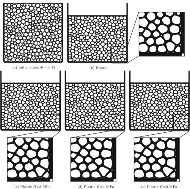
Figure2shows initial configuration and snapshots of the compact state of the assembly for the elastic and elasto-plastic behaviours. Due to particle shape changes, the whole space is nearly filled at the end of the compaction process, and so, the packing fraction (Φ = VS/V, where VS is the
volume of particles and V the total volume) increases. We observe that the shapes of the particles change gradually from circular to polygonal and the plastic particles at the end have a polygonal shape with larger curvatures in comparison with the elastic particles; see the zoom on the deformed packings in Fig.2. Indeed, the plasticity allows these particles overfill the pores for much lower stress than the elastic ones.
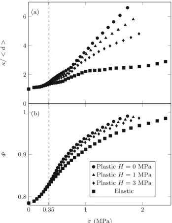
In order to highlight the above feature, the mean value of maximum curvature of the particles κ and the packing fraction Φ as a function of the applied stress σ is presented in Fig.3. σ is computed from the contact forces acting on the bottom wall. As mentioned above, the plastic particles achieve higher values of κ by smaller applied stress σ than the elastic particles. We also observe that for the plastic particles, when the hardening H decreases, the curvature κ increases; i.e. one needs less applied stress to fill the pores of a particu-late system under compression when the hardening of plastic particles is small. This point also features in the evolution of the packing fraction Φ as a function of the applied stress σ . A nonlinear behaviour for the elastic and plastic particles with different rates is observed. To compress the elastic particle packing, we require a larger force than for the plastic parti-cles, and the required force increases for the plastic particles when the hardening augments.
Fig. 2 A snapshot of the initial configuration (a); snapshots of the compacted packings of particles with elastic and elasto-plastic behaviours (with
three values of the hardening parameter H) at packing fraction of Φ= 0.97, and zoom on the particles inside a bottom right window of the deformed packings (b–e)
In Fig.3, we also observe that the plastic results diverge from the elastic ones for σ ! 0.35 MPa. This value is smaller than the yield stress of one plastic particle (σy = 0.4 MPa)
since not all the particles in the packing undergo plastic defor-mation at the same time. Moreover, for all cases, a regime change is observed around the packing fraction of 0.8. This change point can be considered as the jamming point, i.e. Φc " 0.8. Above this point, particle rearrangement is
neg-ligible and the particle shape change controls essentially the packing evolution. One can hence assume that the packing behaviours beyond the jamming point are almost like a con-tinuum medium. Considering the P-wave modulus definition, this assumption allows obtaining the applied stress σ as a function of the cumulative vertical strain ε (ε = ln(h/hi),
with h as the current height of the packing and hi its initial
height) for the elastic particles:
σ − σc= Meff(ε− εc) , (5)
where σcand εcare, respectively, the applied stress and the
vertical strain at the jamming point, and Meff denotes the effective elastic P-wave modulus to be defined. Based on Eq. (5), one may relate σ to the packing fraction Φ and the mean coordination number Z for the elastic particles (see “Appendix 1”):
σ = − M eff 1+c1MK ZΦeff
0 2 4 6 (a) κ / < d > 0 0.35 1 2 0.8 0.9 1 (b) σ (MPa) Φ Plastic H = 0 MPa Plastic H = 1 MPa Plastic H = 3 MPa Elastic
Fig. 3 Mean value of maximum curvature κ of the particles normalised
by their mean diameter < d > (a) and the packing fraction Φ (b) as a function of the applied stress σ for elastic and elasto-plastic material behaviours
where K denotes the particle bulk modulus (K = λ+µ in 2D, with λ and µ as Lamé parameters), c1represents a constant parameter depending on the particle material behaviour and c2is a constant term. Note that since Z can also be defined as a function of Φ (see Eq. (17)), σ is only related to the packing fraction Φ via Eq. (6).
In our previous work [11], considering the Voigt rule of mixtures gives Meff = Φ M with M as the particle P-wave modulus. Here, we consider the packing behaviours beyond the jamming point as a continuum porous medium. Meffcan hence be defined like the effective elastic P-wave modulus for a porous material:
Meff = Geff3G(4Geffeff − Eeff)
− Eeff . (7)
Here, Eeffis the effective Young’s modulus given by [14]: Eeff = E $ 1− pp c %fE , (8)
and the effective shear modulus is [15]:
Geff = G $ 1− pp c %fG , (9)
where p is the porosity ( p= 1 − Φ), fE and fG denote the
characteristic components for Young’s and shear moduli, and pcis the critical porosity, below which the effective Young’s
and shear moduli become zero. This corresponds to below and near the jamming point.
The above relations are defined for the elastic particles. To consider the plastic deformation, the applied stress σ may be decomposed into an elastic part σe and a plastic one σp as
follows:
σ = (1 − fp)σe+ fpσp, (10) where fp is the plastic volume fraction defined as the ratio
between the volume of the plastic regions of particles and their total volume. During compaction process, fp is zero
before the jamming, but beyond the jamming point, it is pro-portional to the vertical strain (hence, the packing fraction). One can therefore assume that fp increase logarithmically
as a function of Φ/Φc: fp= α ln(Φ
Φc), (11)
where α is a constant parameter to be determined. Moreover, the plastic stress σpcan be defined in the following form by
considering Eqs. (5) and (6):
σp= σy+ Meffp (ε− εc), (12) σp= σy− Meff p 1+ Meffp c1 pKpZΦ (ln(Φ)+ c2p), (13) with Meffp = G eff p (4Geffp − Eeffp ) 3Geff p − Eeffp . (14) Eeffp = Ep $ 1− pp c %fE p , (15) Geffp = Gp $ 1− pp c %fG p . (16)
Here, Epis the plastic tangent modulus related to H through: Ep= E H/(E + H) and Gpdenotes the plastic shear
mod-ulus: Gp = Ep/2(1+ νp). Note that, by assuming that the
volume change due to plastic deformation is negligible, one concludes the equality of the elastic and plastic Poisson’s ratios; i.e. νp= ν.
In order to determine several parameters in the elastic and plastic models (Eqs. (5), (6) and (10)), we consider first the elastic simulation results, allowing setting the elastic
0 1 2 σ -σc (M P a) 0 1 2 σ -σc (M P a) 0 1 2 σ -σc (M P a) 0.8 0.85 0.9 0.95 1 0 1 2 Φ σ -σc (M P a) 0 0.05 0.1 0.15 0.2 0.25 ε− εc • Elastic – Analytic model • Plastic H = 0 MPa – Analytic model • Plastic H = 1 MPa – Analytic model • Plastic H = 3 MPa – Analytic model
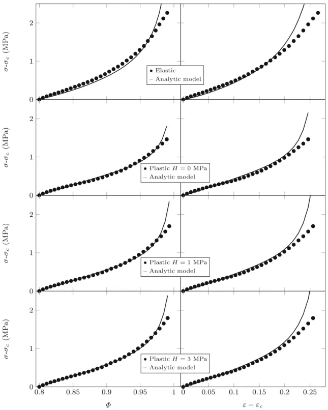
Fig. 4 Excess applied stress σ −σcas a function of packing fraction Φ
and excess strain ε− εcfor elastic and elasto-plastic (with three values
of hardening, H) particles by MPM simulations. σcand εccorrespond
to the jamming point Φc" 0.8. The lines show the predicted behaviours
beyond jamming by the compaction models introduced in this paper; see Eqs. (5), (6) and (10)
parameters. In a similar vein, one can determine the plastic parameters from one of the plastic simulation results by fixing the obtained elastic parameters. In Fig.4, we observe that the predictions of the elastic and plastic models are in good
agree-ment with all MPM simulations by fixing fE = fEp = 1.2,
fG = fGp = 0.2 and pc= 0.201(" 1 − Φc), c1= c1p = 1,
c2= c2p = 0.23(" − ln (Φc))and α= 2.5. Nevertheless, at
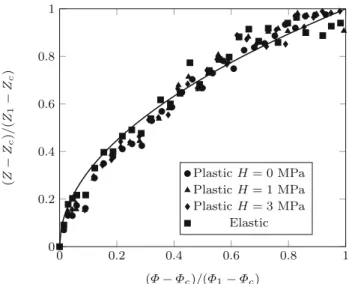
0 0.2 0.4 0.6 0.8 1 0 0.2 0.4 0.6 0.8 1 (Φ − Φc)/(Φ1− Φc) (Z − Zc )/ (Z1 − Zc ) Plastic H = 0 MPa Plastic H = 1 MPa Plastic H = 3 MPa Elastic
Fig. 5 Evolution of the excess mean coordination number Z − Zcas
a function of excess packing fraction Φ− Φcfor elastic and
elasto-plastic particles by MPM simulations. The solid line is power-law fit (Φ− Φc)0.5; see Eq. (17)
the numerical simulations is noticeable. To reproduce well the predictions, the particle discretisation may be refined in order to resolve correctly the small radii of curvature at the contact zones between particles. In consequence, to repro-duce the compaction results, one needs to determine four parameters in the analytical models as well as the jamming state. Moreover, the general feature of the curves shown in Fig.4is more or less similar to the typical compaction curves observed in industrial applications [5,16–18] and the pre-sented empirical model seems to reproduce well these results. However, this model still needs to be validated with a more detailed and quantitative comparison between simulations and experiments.
The evolution of the mean coordination number Z beyond the jamming point as a function of the packing fraction is presented in Fig.5. As shown in the previous works (e.g. [11, 19–21]), the excess coordination number Z− Zcnormalised
by Z1− Zcbehaves as a power law as a function of the excess
packing fraction Φ− Φcnormalised by Φ1− Φc: Z− Zc Z1− Zc = & Φ− Φc Φ1− Φc , (17) where Z1and Φ1correspond to any state after the jamming point. We observe that the elastic and plastic results are uni-fied and fitted by the model (17) independent of the material behaviours.
5 Concluding remarks
This paper presents a compaction study of elasto-plastic soft particle systems using a numerical approach developed in our previous works [9–11]. This parallelised technique is based on coupling of an implicit formulation of the mate-rial point method (MPM) for individual particles and the contact dynamics (CD) method for the treatment of contact interactions. The MPM allows accounting for the realistic mechanical behaviour of individual particles, including elas-tic and plaselas-tic behaviours. Here, we consider the parelas-ticle behaviour as a rate-independent elasto-plastic model based on the bilinear isotropic hardening. A diametrical compaction of one single particle was performed to illustrate the potential of this method to simulate contact interactions between soft elasto-plastic particles.
The MPM-CD approach is then used to simulate the uni-axial compaction of an assembly of soft particles (discs). Obviously, the discs do not represent real particle shapes in industrial applications. But the developed approach can be easily applied to more complex particle shapes [10]. The packings with plastic particles can undergo large deforma-tions at a lower compressive stress in comparison with elastic particles. It is due to the occurrence of weaker stress chains between particles. However, the required compressive stress to achieve high packing fractions increases with hardening for plastic particles. We observed a logarithmic variation of this stress beyond the jamming state with packing fraction for elastic and plastic particles. A model based on porous materials was introduced in order to explain this behaviour. This model reproduced well the numerical results with four parameters to fix. Since the considered particles were nearly incompressible (ν = 0.45), it is interesting to verify and adjust this model for different ranges of compressible parti-cles. An experimental study is also required to validate the proposed model. Finally, it was shown that the coordination number is related to the packing fraction by a power-law function beyond the jamming transition.
Acknowledgements This work (Project ID 1502-607) was publicly
funded through ANR (the French National Research Agency) under the “Investissements d’avenir” programme with the reference ANR-10-LABX- 001-01 Labex Agro and coordinated by Agropolis Fondation, France, under the frame of I-SITE MUSE (ANR-16-IDEX-0006). We are also grateful to the Genotoul bioinformatics platform Toulouse Midi- Pyrenees (Bioinfo Genotoul) for providing computing resources.
Compliance with ethical standards
Conflict of interest The authors declare that they have no conflict of
Appendix 1: Relation between the applied
stress,
!, and the packing fraction, 8, for an
elastic packing under uniaxial compression
We assume that the packing of particles behaves almost as a continuum porous medium beyond the jamming point under uniaxial compression. Hence, in this range the applied stress σmay be related to the cumulative vertical strain ε through an effective P-wave modulus Meff:
σ = Meffε . (18)
One may further assume that the particle bulk modulus K relates the volume increment dVSof particles to the effective
stress increment dσSin particles: KdVS
VS = −dσS. (19)
σcan be related to σSas follows:
σ = c1ZΦσS, (20)
where c1is a material constant to be determined. Given that dε= dVS/VS− dΦ/Φ and using Eqs. (18), (19) and (20),
the following differential equation to solve is obtained:
' 1+cMeff 1K ZΦ ( dσ = ) Meff c1K ZΦ $ dZ Z + dΦ Φ % +dMeff Meff * σ −MeffdΦ Φ . (21)
By knowing that Meff and Z are related to Φ (see Eqs. (7) and (17)), the integration of the differential equation (21) yields:
σ = − M eff 1+c1MK ZΦeff
(ln(Φ)+ c2) , (22)
where c2is the integral constant.
References
1. Sinka C (2007) Modelling powder compaction. KONA Powder Particle J 25:4
2. Pitt KG, Webber RJ, Hill KA, Dey D, Gamlen MJ (2015) Com-pression prediction accuracy from small scale compaction studies to production presses. Powder Technol 270:490
3. Wu CY, Ruddy O, Bentham A, Hancock B, Best S, Elliott J (2005) Modelling the mechanical behaviour of pharmaceutical powders during compaction. Powder Technol 152:107
4. Krok A, Peciar M, Fekete R (2014) Numerical investigation into the influence of the punch shape on the mechanical behavior of pharmaceutical powders during compaction. Particuology 16:116 5. Moghaddam M, Darvizeh R, Davey K, Darvizeh A (2018) Scaling
of the powder compaction process. Int J Solids Struct 144:192 6. Wu CY (2008) DEM simulations of die filling during
pharmaceu-tical tabletting. Particuology 6:412
7. Barnabe M, Blanc N, Chabin T, Delenne JY, Duri A, Frank X, Hugouvieux V, Lutton E, Mabille F, Nezamabadi S et al (2017) Multiscale modeling for bioresources and bioproducts. Innov Food Scie Emerg Technol 46: 41–53
8. Choi J, Gethin D (2009) A discrete finite element modelling and measurements for powder compaction. Model Simul Mater Sci Eng 17:035005
9. Nezamabadi S, Nguyen T, Delenne JY, Radjai F (2017) Modeling soft granular materials. Granul Matter 19:8
10. Nezamabadi S, Radjai F, Averseng J, Delenne JY (2015) Implicit frictional-contact model for soft particle systems. J Mech Phys Solids 83:72
11. Nezamabadi S, Frank X, Delenne JY, Averseng J, Radjai F (2019) Parallel implicit contact algorithm for soft particle systems. Com-put Phys Commun 237:17
12. ANSYS (2009) ANSYS theory reference for the mechanical APDL and mechanical applications, 12th edn. In: ANSYS theory ref-erence for the mechanical APDL and mechanical applications. ANSYS Inc., Canonsburg, PA
13. Andersen S, Andersen L (2010) Analysis of spatial interpolation in the material-point method. Comput Struct 88:506
14. Kováˇcik J (1999) Correlation between Young’s modulus and poros-ity in porous materials. J Mater Sci Lett 8:1007
15. Kováˇcik J (2001) Correlation between shear modulus and porosity in porous materials. J Mater Sci Lett 20:1953
16. Samimi A, Hassanpour A, Ghadiri M (2005) Single and bulk com-pressions of soft granules: experimental study and DEM evaluation. Chem Eng Sci 60:3993
17. Stasiak M, Tomas J, Molenda M, Rusinek R, Mueller P (2010) Uniaxial compaction behaviour and elasticity of cohesive powders. Powder Technol 203:482
18. Zhou M, Huang S, Hu J, Lei Y, Zou F, Yan S, Yang M (2017) Experiment and finite element analysis of compaction densification mechanism of Ag–Cu–Sn–In mixed metal powder. Powder Technol 313:68
19. O’Hern C, Silbert L, Liu A, Nagel S (2003) Jamming at zero tem-perature and zero applied stress: the epitome of disorder. Phys Rev E 68:011306
20. van Hecke M (2010) Jamming of soft particles: geometry, mechan-ics, scaling and isostaticity. J Phys Condens Matter 22:033101 21. Zhang J, Majmudar TS, Sperl M, Behringer R (2010) Jamming for
a 2D granular material. Soft Matter 6:2982
Publisher’s Note Springer Nature remains neutral with regard to