HAL Id: hal-02968127
https://hal.archives-ouvertes.fr/hal-02968127
Submitted on 15 Oct 2020
HAL is a multi-disciplinary open access
archive for the deposit and dissemination of
sci-entific research documents, whether they are
pub-lished or not. The documents may come from
teaching and research institutions in France or
abroad, or from public or private research centers.
L’archive ouverte pluridisciplinaire HAL, est
destinée au dépôt et à la diffusion de documents
scientifiques de niveau recherche, publiés ou non,
émanant des établissements d’enseignement et de
recherche français ou étrangers, des laboratoires
publics ou privés.
Failure Analysis of a Collaborative 4-1 Cable-Driven
Parallel Robot
Stéphane Caro, Jean-Pierre Merlet
To cite this version:
Stéphane Caro, Jean-Pierre Merlet. Failure Analysis of a Collaborative 4-1 Cable-Driven Parallel
Robot. European Conference on Mechanism Science (EuCoMeS 2020): New Trends in Mechanism
and Machine Science, 89, pp.440-447, 2020, �10.1007/978-3-030-55061-5_50�. �hal-02968127�
Cable-Driven Parallel Robot
St´ephane Caro and Jean-Pierre MerletAbstract Cable-Driven Parallel Robots (CDPRs) have been little used so far for collaborative tasks with humans. One reason is the lack of solutions to guarantee the safety of the operators in case of failure. Therefore, this paper aims to deter-mine the possible failures of CDPRs when they are used for collaborative work with humans and to provide technical solutions to ensure the safety of the operators. A translational three degrees-of-freedom CDPR composed of four cables connected to a point-mass end-effector is considered as an illustrative example. The cables are supposed to be ideal, namely, they are not elastic and do not exhibit sagging.
Key words: cable-driven parallel robot, cable sagging, failure, safety, collaborative
1 Introduction
Cable-driven parallel robots (CDPR) are a special class of parallel robot where the rigid legs/links of a classical parallel robot (CPR) are substituted by cables that can be wound or unwound. This type of actuation offers a lower mechanical complexity (passive joints may not be used) compared to CPR and, more importantly, a wider range of leg lengths, thereby allowing for a larger workspace. In this paper we will consider a specific CDPR, the so-called N −1 CDPR, having N cables that are all attached to the same point B on the platform, whose center of mass is below this point. The cable lengths L0are changed by using rotary winches, whose rotations are
measured by encoders. Provided that N ≥ 3, such a CDPR is a 3-dof robot allowing only translational motion of the load, which is appropriate for many tasks [1, 3], e.g. for 3D printing [2] or metrology [13]. Basic control of the CDPR is based
S. Caro, Centre National de la Recherche Scientifique (CNRS), LS2N, Nantes, 44321 France e-mail: [email protected]
J-P. Merlet, INRIA Sophia-Antipolis, 2004 Route des Lucioles, France e-mail: [email protected]
2 St´ephane Caro and Jean-Pierre Merlet
on a feedback loop on the L0that are estimated by using the measurement of the
rotation angle of the winches. In the scope of this paper, the cables are supposed to be ideal, namely, they are not elastic and do not exhibit sagging. They are made up of synthetic material and, as a consequence, do not exhibit the dangerous whip effect of steel cables. As the winches are assumed to be irreversible, there won’t be any change in cable lengths if they are not actuated.
Furthermore, the winch dynamics is supposed to be not sufficient to correct the fast motion of the load during a failure.F0(x, y, z) denotes the reference with z the
vertical axis.
This paper aims to determine the possible failures of CDPRs when they are used for collaborative work with humans, especially failures that may lead to a danger for the human operators. Failures of parallel robots have been addressed in [9, 11, 12] and for CDPR in [7,8], but not with the purpose of ensuring the safety of co-workers.
2 Kineto-static analysis of a 4-1 CDPR
Being given the platform pose of a CDPR the lengths of the 4 cables are uniquely determined. On the other hand as soon as the lengths of 3 cables under tension are fixed, then the platform pose will be fully determined. As the cable lengths are never exactly measured we are not able to reach a platform pose, for which the four cables are in tension. While performing a trajectory the CDPR will usually have at most three cables in tension, possibly going temporarily through poses where all four cables are in tension, but we are not able to determine such a case. If Ai denotes
the winch output point of cable i we will consider the convex hull H of the Ai
points in the plane z = 0 and Aipwill denote the projection of Aiin this plane and
if M is a pose, then Mpwill be its projection in the plane. It is easy to show that
if Mpis strictly inside the triangle Aip, Aj p, Ak p (denoted as (i, j, k) for short), then
a static equilibrium will be obtained when cables i, j, k are in tension while cable l6= i, j, k is slack. However, there will be another cable configuration i, j, l with k slack that also leads to a mechanical equilibrium of the platform. Hence for a given platform pose two possible cable configurations, named the main cables, that share two cables (i, j) and only differ by the third cable, lead to a static equilibrium of the platform. In what remains, the Cartesian coordinates of points Aiexpressed in meter
are the following: OA1(-8,5,5), OA2(-8,-5,5), OA3(8,-5,5), OA4(8,5,5). The four
points have the same height and lead to a rectangular workspace.
3 Possible failures
The failures that are considered in this paper and may occur for a CDPR are the following:
2. failure of an encoder or of a motor or its control module: such failure may easily be detected as the integration of the voltage sent to the motor combined with a simple motor model will provide information of the expected motion of the encoder. If this information is not coherent with the measurement either because of a failure of the encoder or of the motor, we may stop the CDPR and because of the usual high resolution of the encoder, the displacement of the platform will minimal;
3. the loop effect: uncoiling an already slack cable may lead to a loop at the winch level that reverts the normal coiling process. Consequently, the cable length may decrease instead of increasing and therefore the altitude of the load will increase. This failure cannot be detected by using only the estimation of the L0based on
the measurement of the winch rotation angles.
4. the winch may have a mechanical failure, e.g. break or losing the clutch that couples the drivetrain to the coiling unit.
5. depending on the velocity of the platform before an emergency stop, the robot may undergo significant sway motion, often putting two cables under tension and making the third cable loose.
6. cables can get stuck in the winch or on guiding pulleys. Cables leaving the pulleys may also slide about nearby elements.
Our objective is to ensure the safety of the operator. There are several means for this purpose:
• immobilize the robot
• move the robot at a low speed toward a safe pose
• move the load from its current pose along the vertical to a safe altitude to avoid any contact with the workers or environment
• put the load as quickly as possible on the ground to limit its motion
There are no general strategies that may be applied for each case and In this paper, it is assumed that this safety will be guaranteed if the unexpected motion of the CDPR is such that the load cannot reach an altitude that is lower than a given value zland
higher than a threshold zhbecause the cable tensions increase with the altitude of
the platform and may lead to damages on the CDPR. Note that this assumption is not restrictive and the proposed methods can be extended to deal with other safety definition such as the avoidance of a given region.
3.1 Cable breaking
With only the measurement of the L0the breaking of a cable cannot be detected.
Hence the safety has to be ensured by the robot design and by restricting its workspace. As seen in Sec. 2, we have for a given pose in most cases three ca-bles only in tension. The corresponding cable configurations are i, j, k or i, j, l. The breaking of k (l) will not affect the CDPR behaviour that much because the cable configuration will switch to i, j, l(k) with a little displacement of the platform. On
4 St´ephane Caro and Jean-Pierre Merlet
the contrary, the robot behaviour will be highly affected if one of the main cables i, j breaks down.
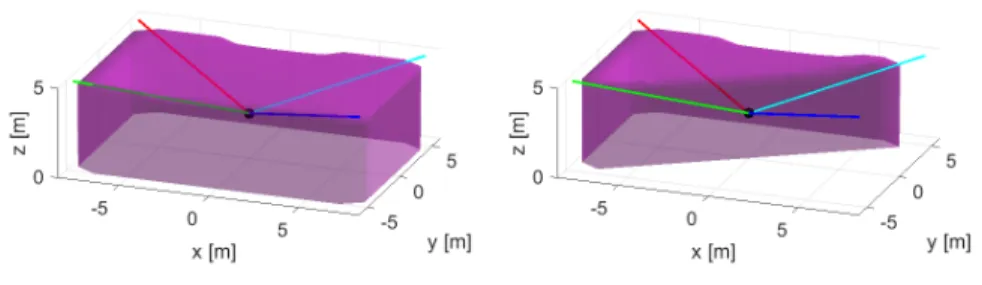
Fig. 1 On the left the static workspace of the CDPR. On the right the static workspace of the CDPR after cable 3 (blue cable) breakage.
Figure 1(a) shows the area where the platform can be in a static equilibrium for the CDPR at hand. Figure 1(b) illustrates the static workspace of the manipulator after one cable breakage.
Let us assume thatH is a rectangle whose corners are numbered 1,2,3,4 and assume that at its current pose such that Mpis located both in the triangle 123 and
124 leading to two possible cable configurations having 1,2 as main cables. If the CDPR is in the configuration 123 and cable 1 (2) breaks down, then the load will swing around the A2A4(A1A3) line meaning that the load will move on a circle in a
vertical plane that is perpendicular to A2A4(A1A3) whose radius can be obtained as
a function of the lengths of cables 2,4 (1,3). It is easy to show that if M lies in the cylinder with axis A2A4(A1A3) and radius za− zl, then the load will not go below zl
during the swinging motion after the breakage of cable 1 (2). However we have also to limit the load height to zhin this cylinder. A fully safe zone is therefore obtained
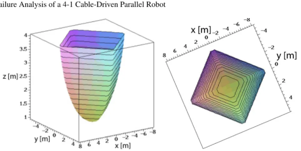
as the intersection of these two cylinders that lie below the altitude zh. Figure 2
shows the full safe zone obtained for zl= 1, zh= 4. From Figs. 1(a) and 2, it is
noteworthy that this safety consideration drastically shrink the CDPR workspace.
3.2 Adding measurements
As seen previously the measurement of the L0is not sufficient to ensure the safety of
CDPRs. Therefore it is necessary to consider other measurements with the objective to detect an abnormal behavior for the cables or for the whole CDPR, that may occur very quickly (e.g. during a cable breakdown). For this purpose we may measure at a high rate the cable tensions, the cables angles with respect to the horizontal at A or B (with an optical sensor [6] or an IMU located close to B), or the load altitude
Fig. 2 3D and top view of the safe zone when one cable breaks
(with a vertical distance sensor). Tension measurement is not satisfactory because it will be very difficult to distinguish between a normally slack cable or a broken cable. Measuring the z coordinate of the platform, which has an interest for control, is appropriate except in the case of a non-main cable breakage while measuring the angles covers all failure cases. In summary there are multiple sensor possibilities to detect a failure of such a CDPR.
3.3 Zones covered by the cables
In order to avoid any collision between the human operator and the cables, it is pos-sible to prevent the human operator from getting into zones spanned by the cables with intangible barriers. For that matter, the zone spanned by each cable should be determined first. Some approaches are proposed in the literatureare to determine the the cable span of CDPRs [4, 5, 10]
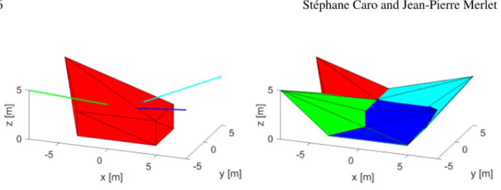
For instance, Fig. 3(a) shows the area spanned by cable 1 (red cable) when the end-effector covers the rectangular parallelepiped of size 8 m × 5 m × 2.5 m. Fig. 3(b) the area spanned by the four cables when the end-effector covers the same regular shape. Accordingly, the white areas are free of collision with cables and can be travelled by the human operator while being sure that he/she will not get in con-tact with cables as long as there is no cable breakage. From Fig. 3, it is apparent that no human operator is allowed to approach the robot because most of the space is spanned by the cables. In this case, a typical safety measure is a fence or technical solutions must be adopted to allow interaction between human operators and the cables for low speed operations.
6 St´ephane Caro and Jean-Pierre Merlet
Fig. 3 On the left the area spanned by cable 1 (red cable) when the end-effector covers the rect-angular parallelepiped of size 8 m × 5 m × 2.5 m. On the right the area spanned by the four cables when the end-effector covers the same regular shape. Cables 1, 2, 3 and 4 are red, green, blue and cyan, resp. The white areas are free of collision with cables.
4 Ensuring safety
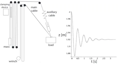
A complete safety for the CDPR may be obtained by doubling each cable with a passive auxiliary cable as shown in Fig. 4. This cable goes from the load to an output point close to A and has a counterweight at its free end. The cable goes through a pulleys circuit, which is designed in such way that when the main extend from its minimal to its maximal length, then the counterweight moves from the bottom to the top of the mast. On the last branch of the cable loop, a clamping mechanism allows one to stop the cable motion. The mass of the counterweight is just sufficient to overcome the friction in the pulleys and the tension in the auxiliary cables. Therefore, this mass does not modify the platform pose, although it will usually decrease the tensions in the four main cables. As an example we assume that at time 0 the CDPR is at pose (-6,-3,2) (which is outside of the safe zone) when cable 2 breaks down. At time 0.1s the controller detects that cable 2 has broken down, stops the winches of all cables and clamps the auxiliary cable 2, whose stiffness is 10 000 N/m and has a damping factor of 200 Ns/m. Figure 4 shows the evolution of the z of the load as a function of time. It may be seen that the load quickly converges toward a safe position.
It may be noted that the auxiliary cables may be very close to the main cables, so that cable interference will not be an issue.
It may be tought that adding 4 cables, even passive ones, induces an increasing complexity. Hence we have investigated the use of a single auxiliary cable that will release a counterweight after a failure detection in order to raise the load at a safe height. However it has appeared that it is very difficult to determine the location of the output point of this cable and the mass of the counterweight so that the CDPR may be put in a safe position whatever the initial breakdown pose is. The dynamics of such a system is relatively simple but is very sensitive to the mass of the coun-terweight: if the mass is too low the system may fail to raise the load, while for a larger mass we obtain a very large upward motion of the load before reaching the
Fig. 4 On the left the principle of safety ensured by auxiliary cables. On the right the evolution with respect to time of the z-coordinate of the load after cable 2 breakdown.
static equilibrium. Such a motion will put a large stress on the CDPR structure that will lead to additonal safety issues.
5 Conclusion
This paper dealt with the possible failures of CDPRs when they are used for col-laborative work with humans and provided some technical solutions to ensure the safety of the operators. There is no general strategy that can be applied in each case for ensuring this safety. We have considered a translational three degrees-of-freedom CDPR composed of four cables connected to a point-mass end-effector as an illustrative example. Failure possibilities have been identified, together with sen-sory means to detect the failute. The behaviour of the CDPR was studied in case of cable breakage and failure of an actuator and the loop effect was also investigated. Some technical solutions were proposed to ensure the safety of the human operator working in collaboration with the CDPR. For instance, a concept based on auxil-iary cables and a clamping device was introduced to ensure safety in case of cable breakage.
Acknowledgements This work was partly supported by the ANR CRAFT, grant ANR-18-CE10-0004.
8 St´ephane Caro and Jean-Pierre Merlet
References
1. Alikhani, A., et al.: Design of a large-scale cable-driven robot with translational motion. Robotics and Computer-Integrated Manufacturing 27(2), 357–366 ( April 2011)
2. Barnett, E., Gosselin, C.: Large-scale 3d printing with a cable-suspended robot. Additive Manufacturing 7, 27–44 ( July 2015)
3. Borgstrom, P., et al.: Discrete trajectory control algorithms for NIMS3D, an autonomous un-derconstrained three-dimensional cabled robot. In: IEEE Int. Conf. on Intelligent Robots and Systems (IROS), pp. 253240. San Diego ( September, 22-26, 2007)
4. Farzaneh Kaloorazi, H., Tale Masouleh, M., and Caro, S.: Collision-Free Workspace of Paral-lel Mechanisms based on an Interval-based Approach. Robotica, Vol. 35(8), pp. 1747–1760. 5. Lesellier M., Gouttefarde M.: A Bounding Volume of the Cable Span for Fast Collision
Avoidance Verification. In: Cable-Driven Parallel Robots. (CableCon), Springer, p. 173–184, Krakow, Poland, 2019
6. Merlet, J.P.: An experimental investigation of extra measurements for solving the direct kine-matics of cable-driven parallel robots. In: IEEE Int. Conf. on Robotics and Automation. Bris-bane ( May, 21-25, 2018)
7. Moradi, A.: Stiffness analysis of cable-driven parallel robot. Ph.D. thesis, Queens University, Kingston ( April 2013)
8. Notash, L.: Failure recovery for wrench capability of wire-actuated parallel manipulators. Robotica 30(6), 941–950 ( September 2012)
9. Notash, L., Huang, L.: On the design of fault tolerant parallel manipulators. Mechanism and Machine Theory 38(1), 85–101 ( January 2003)
10. Pott, A.: Determination of the Cable Span and Cable Deflection of Cable-driven Parallel Robots. In: Cable-driven Parallel Robots (CableCon), Springer, p. 106–116, Laval, Canada, 2017
11. Roberts, R., et al.: Characterizing optimally fault-tolerant manipulators based on relative ma-nipulability indices. In: IEEE Int. Conf. on Intelligent Robots and Systems (IROS), pp. 3925– 3930. San Diego ( September, 22-26, 2007)
12. Ukidve, C., McInroy, J., Jafari, F.: Parallel manipulators, Towards new applications, chap. Quantifying and optimizing failure tolerance of a class of parallel manipulators, pp. 45–68. ITECH ( April 2008)
13. Williams II, R., Albus, J., Bostelman, R.: 3D cable-based cartesian metrology system. J. of Robotic Systems 21(5), 237–257 (2004)