HAL Id: cea-01365898
https://hal-cea.archives-ouvertes.fr/cea-01365898
Submitted on 13 Sep 2016
HAL is a multi-disciplinary open access
archive for the deposit and dissemination of
sci-entific research documents, whether they are
pub-lished or not. The documents may come from
teaching and research institutions in France or
abroad, or from public or private research centers.
L’archive ouverte pluridisciplinaire HAL, est
destinée au dépôt et à la diffusion de documents
scientifiques de niveau recherche, publiés ou non,
émanant des établissements d’enseignement et de
recherche français ou étrangers, des laboratoires
publics ou privés.
Sr 2 IrO 4 magnetic phase diagram, from resistivity
L Fruchter, G Collin, Dorothée Colson, V Brouet
To cite this version:
L Fruchter, G Collin, Dorothée Colson, V Brouet. Sr 2 IrO 4 magnetic phase diagram, from resistivity.
European Physical Journal B: Condensed Matter and Complex Systems, Springer-Verlag, 2014.
�cea-01365898�
arXiv:1410.5726v1 [cond-mat.str-el] 21 Oct 2014
L. Fruchter, G. Collin, D. Colson+ and V. Brouet
Laboratoire de Physique des Solides, C.N.R.S. UMR 8502, Universit´e Paris-Sud, 91405 Orsay, France and
+
Service de Physique de l’Etat Condens´e, CEA-Saclay, 91191 Gif-sur-Yvette, France (Dated: Received: date / Revised version: date)
We show that the transition to the antiferromagnetic state in zero magnetic field does show up in the transverse resistivity, for which we point out the possibility for a direct spin orientation effect. In an applied field, we propose that the transition is split into two lines, corresponding to in-plane and out-of-plane magnetic ordering. This picture is corroborated by transverse magnetization measure-ments. The magnetic phase diagram for Sr2IrO4 was investigated, using the angular dependence of
the resistivity transverse to the IrO2 planes.
PACS numbers: 75.30.Kz,75.47.Lx,75.70.Tj
I. INTRODUCTION
In the recent years, iridium oxides have become a new playground for the study of electron correlation ef-fects. Indeed, while extended 5d orbitals reduce the electron-electron interaction, as compared to the 3d tran-sition metal compounds as cuprates, strong spin or-bit coupling (SOC) associated to the heavy Ir com-petes, together with the on-site Coulomb interaction, with electronic bandwidth to restore such correlations[1]. Amongst these compounds, the Ruddlesden-Popper se-ries, Rn+1IrnO3n+1 where R= Sr, Ba and n = 1,2,∞,
has attracted much of the attention, in particular due to the structural similarities of these perovskites with the cuprates compounds. Sr2IrO4, where one IrO2 layer
al-ternates with an SrO layer, is structurally similar to the first discovered cuprate superconductor, (La,Ba)2CuO4.
The physics of the latter is the one of an antiferromag-netic Mott insulator, with a magantiferromag-netic interaction de-scribed within the framework of a spin-1/2 Heisenberg model. It was early proposed that the strong SOC in the iridate perovskite actually allows for an effective local-ized state different from this spin-1/2 state, entangling spin and orbital degrees of freedom, with total angular momentum Jef f = 1/2. This spin-orbital insulating state
was proposed to be the analog of a Mott insulator [1]. The antiferromagnetic order in Sr2IrO4 is now well
documented[2, 3]. The moments (0.2 µB/Ir) lay in-plane
and order at TN ≃ 240 K. As for La2CuO4, the loss
of the inversion symmetry in the non cubic structure, due to a rotation of the oxygen octahedra, allows for a Dzyaloshinsky-Morya interaction, which in turn induces a canting of the spins and a ferromagnetic component in the IrO2 planes [4–6]. The net moment (0.14 µB/Ir),
which is coupled antiferromagnetically from plane to plane in zero field, align ferromagnetically with an in-plane field H ≈ 0.2 T [7]. Recent ab initio computa-tions conclude that the dominant magnetic interaction is of Heisenberg type, with little effect of the geometri-cal factors on the exchange coupling [8]. As shown in ref. 19, the absence of a critical behavior in the in-plane magnetic correlation length at TN is also in favor of a
two-dimensional Heisenberg behavior with large
quan-tum fluctuations. On the basis of such a description, it has been proposed that Sr2IrO4 may exhibit electronic
properties similar to the ones of the cuprates, including superconductivity [9]. The nature of the insulating state is however the subject of debate. First, the realization of the Jef f = 1/2 state itself may be questioned, as it
re-quires a perfect orbital degeneracy, which is not obtained in Sr2IrO4 where the octahedra are strongly elongated
[10]. The location of a metal-insulator transition, either in the paramagnetic state as for a Mott-Hubbard tran-sition [11], or coincident with the magnetic trantran-sition as for a Slater-type transition [12] is controversial.
As first noticed by Kini et al [13], no anomalies can be detected in resistivity at TN. The authors proposed that
this could result from the fact that localized states shifts the Fermi level away from the band edges affected by spin polarization. A time-resolved optical study found that the metal-insulator transition takes place over a wide temperature range 0.7 . T /TN . 1.4, thus
account-ing for the absence of any sharp anomaly in transport and thermodynamic quantities[14]. Well below TN, for
T . 100 K, large anisotropic magnetoresistance as well as magnetodielectric effects were observed (Refs. 15, 16). It was proposed that the magnetoelectric effects result from the competition of antiferromagnetic and ferromagnetic coupling, at low and high temperature respectively[16]. Here, we show that there is actually a small but clear signature of the magnetic transition in zero field in the transverse resistivity. This allows to use magnetotrans-port as a probe to establish a magnetic phase diagram up to TN for this compound. We suggest that the magnetic
transition under magnetic field is split into two lines, cor-responding to in-plane and out-of-plane magnetic order-ing. In the ordered region, we propose that spin orienta-tion has a direct impact on resistivity.
II. RESISTIVITY AND TRANSVERSE MAGNETOMETRY
The results below where obtained with a Sr2IrO4single
crystal, with dimensions 300 x 200 x 30 µm3. It was
2
similar to the one in Ref. 2. We denote a and b the crystal lattice vectors of the superstructure in the IrO2planes[4].
Low-resistance contacts were achieved using silver epoxy annealed at 500 C in oxygen atmosphere. Although we present only the data obtained with one crystal, we have checked that the reported behavior is typical of what can be observed in several other similar undoped samples.
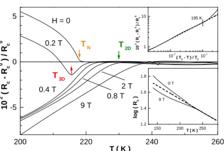
Careful investigation of the c-axis resistivity reveals the existence of an anomaly at a temperature close to the reported TN for the undoped material. The anomaly
is actually very small (Fig. 1, inset), but the sharp jump in the resistivity temperature derivative in zero magnetic field unambiguously points towards a well defined phase transition at TN = 217± 0.5 K (Fig. 1). Quantitatively,
the evaluation of the resistance change below TN requires
subtracting some arbitrary background, as obtained from the high temperature resistivity, and we have used a lin-ear fit of the resistance logarithm to reveal an increase of the resistivity in zero field below the transition (Fig. 1, lower inset). At least close to the transition tempera-ture, little error is likely made due to the sharp transition, and a scaling of the resistivity change may be attempted. This yields, within a ≈ 20 K interval, a scaling exponent 0.55 ± 0.05. We did not observe such an anomaly for the in-plane resistivity. Previous studies did not uncover such a feature, although a tiny specific heat jump could be evidenced at TN (Ref. 16).
Applying a magnetic field along the c-axis and using the same procedure to uncover the resistivity anomaly shows that there is a “splitting” of the transition with the field (Fig. 1). The positive magnetoresistance anomaly shifts to lower temperature (as an example, data in Fig. 1 allows to assign a transition temperature, noted T3D,
215.5 ± 0.5 K with H = 0.2 T), while a negative contri-bution to the magnetoresistance shows up above TN (as
an example, data in Fig. 1 allows to assign a transition temperature, noted T2D, 236 ± 2 K with H = 9 T). With
the applied field the transition at T3D retains its sharp
character at small field, while the transition at T2D
ap-pears to be smoother. The existence of the upper branch implies that the transition temperature obtained from high field studies (as in magnetometry) must be overesti-mated. Data in Fig. 1 suggests, in the present case, that a maximum shift ∆T2D≈20 K is obtained for H ≈ 7 T.
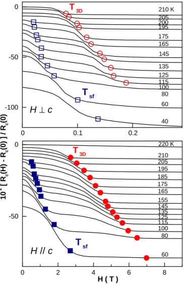
With a field applied parallel to the conducting planes, the behavior is found similar, with a transition temper-ature increase somewhat larger (Fig. 2, open symbols). At T3D, both the sign of the resistance anomaly and the
sharpness of the transition point towards similarity with the zero field low temperature phase, but the anomaly is quickly washed out in a small magnetic field (Fig. 1). However, we find that a kink in the magnetoresistance substitutes to this anomaly (Fig. 3), allowing to extend the definition of T3D to low temperature in Fig. 3
(cir-cles). This defines two branches emerging from the (TN,
H = 0) point (which we denote T3D(H) and T2D(H),
respectively in Fig. 2).
Finally, investigating lower temperatures in the same
way shows that a third characteristic temperature may be evidenced, which coexists with the former in the tem-perature range 80 K . T . 175 K (Fig. 3, squares). We denote this temperature Tspinf lip(H) and also report it in
Fig. 2. For all three branches of the diagram, the charac-teristic magnetic field allowing to cross a branch is found smaller when applied parallel to the conducting plane (Fig. 3). Then, the crossovers observed in the parallel configuration are not a consequence of the sample mis-alignment that unavoidably occurs (which we estimate a few degrees), but are genuinely induced by the parallel field component. The large negative magnetoresistance that we observe at low temperature is similar to the one reported earlier by Ge et al below T = 100 K (Ref. 15), although T3D(H) appears to occur at somewhat lower
field in our case (for instance, H ≈ 1 T at T = 50 K in the present case, and H ≈ 3 T in ref. 15). Our data allow to draw the T3D,spinf lip(H) lines up to
tempera-tures close to TN and indicate that the resistance change
at small field at the T3D(H) line is similar to the one
observed at T = TN and H = 0.
As noticed above, the procedure to evaluate the resis-tance change at the transition is quite arbitrary, which may be a problem in the case of a smooth variation. Angular dependent magnetoresistance, however, confirm the general trend for T2D(H). Indeed, rotating a large
magnetic field around the c-axis reveals the existence of a four-fold contribution to the (negative) magnetoresis-tance (Figs. 5). The angular-dependent contribution is typically only a few percent of the total magnetoresis-tance in Fig. 3, and is found maximal along the a and b axis of the crystal. The temperature dependence of the four-fold component extracted in Fig. 5 confirms, with no need for a high-temperature background fit, the existence of an onset at T2D. A two-fold angular component is also
present, which vanishes with increasing temperature si-multaneously with the four-fold component. However, while the four-fold component temperature dependence appears similar to the one of some order parameter (as for the zero field anomaly), the two-fold component sat-urates with decreasing temperature.
Finally, we have performed torque measurements on this crystal, Γ = µ0m × H, which provides the
magne-tization component transverse to the applied magnetic field. Typical results are shown in Fig. 4 for three points in the H -T plane, representative of three distinct regimes in Fig. 2. In the paramagnetic domain, torque is a pure four-fold sine, suggesting a simple anisotropic magnetic susceptibility contribution, as for a two-dimensional sys-tem. In the high field regime, a distorted sine indicates that the magnetic moment may no longer be decomposed into two independent linear contributions, which could sign a smooth rotation of the magnetization. Finally, in the intermediate field regime, the torque signal develops a discontinuity (for the data shown, at ≈ 12 deg. from the c-axis), which possibly originates from a spin flip.
III. DISCUSSION
We first comment on the lower line, Tspinf lip(H). The
problem of the observation of a very large magnetoresis-tance associated to the presence of a weak ferromagnetic state induced by the magnetic field was already encoun-tered in the case of cuprates[6, 17], and received a quan-titative interpretation in the case of La2CuO4[18]. Two
contributions should actually be distinguished: one due to the change in the transfer integrals and linked to the orientation of the IrO6octahedra, as proposed in Ref. 15,
the other one as a pure spin configuration effect. Could the latter contribute in the present case ? In La2CuO4, in
the orthorhombic phase, the CuO6 octahedra are tilted
from the CuO planes by α ≈ 3 deg. (inducing a ferro-magnetic component perpendicular to the planes). This allows an antisymmetric superexchange term in the spin Hamiltonian, which would otherwise be zero due to sym-metry in the tetragonal phase[6]. In Sr2IrO4, IrO6
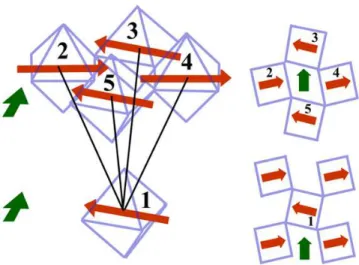
oc-taheadra are tilted in the IrO planes by α ≈ 11 deg. (inducing a ferromagnetic component in the planes) and the compound is tetragonal. This also destroys the in-version center which exists midway between the Ir atoms, and allows for a non zero antisymmetric superexchange term[4] (Fig. 6). Equivalently, due to the tilt of the IrO6
octahedra, the transfer integral between one Ir atom and its four nearest neighbors in the next adjacent plane are unequal. As a consequence, interchanging magnetic sub-lattices, as could be induced by a spin flip, may strongly influence the transverse conductivity in this case also.
In Ref. 18, it was proposed that the transverse re-sistivity is controlled by the localization length in the 3D variable-range hopping regime (VRH). In the present case, resistivity can be fitted with the conventional ex-pression for three-dimensional VRH, ρ ∝ exp (T0/T )1/4,
using T0 = 6 105 K (where T0 ∝ λ−3, and λ is the
transverse localization length – see Ref. 18 and Refs therein). This yields for the ratio of the hopping length to the localization radius l/λ ≈ (T0/T )1/4 ≈ 7,
in-dicating that charge hopping from impurity centers is controlled by the pure material transfer integrals be-tween sites[18]. Using λ ∝ t1/2, where t is some
ef-fective transfer integral between planes, we expect in this case a relative change δρ/ρ ≈ −3
8(T0/T )
1/4δt/t.
According to Ref. 18, a flip of the spins required to align ferromagnetic moments in the plane is associated to a change δt/t ≈ 1
2(J⊥/Jk)(κk/κ⊥)
4(m
⊥/mk)2, where
mk(⊥)is the in-plane (transverse) effective mass, Jk(⊥)is
the in-plane (transverse) exchange coupling, and κk(⊥)is
the corresponding reciprocal lattice constant. We have κk/κ⊥= 1.8, J⊥/Jk≈10−5(a value comparable to that
for La2CuO4, Ref. 19) and m⊥/mk > 20 (this is
eval-uated by the ratio of the bandwidth for J=1/2 along ΓX and NC[12]). This yields δρ/ρ = 1
2δt/t > 6 10
−2.
Though this is only a rough estimate and magnetic con-figurations for both cases are different, this illustrates that an effect comparable to the one that we observe may be expected from the spin contribution alone. We expect
this contribution to be significant at the Tspinf lip(H) line,
where there is a field-induced ferromagnetic moment[15]. Then, within this hypothesis that the resistivity change results from the larger transverse transfer integral associ-ated to magnetic ordering, we may tentatively relate the observed scaling of the resistivity to a critical exponent. We expect the resistance change to be proportional to the phase transition order parameter associated to interplane spin ordering, M (this may be assumed in the framework of a two-fluid model, for which there is an amount n ∝ M of ordered moments associated to a larger transfer inte-gral). As a result, the scaling exponent for the resistivity is identical to the conventional exponent β for the or-der parameter. The value obtained, β ≃ 0.55, is close to the one for a mean field type transition (β = 0.5). In Ref. 19, the transverse fluctuation correlation length above TN yielded a critical exponent ν = 0.75 ± 0.05.
This value is far off the mean field value (ν = 0.5). This discrepancy could sign the limit of the present analysis for the resistivity scaling, made within a simple static picture. Also, the scaling in Ref. 19 relates to long range correlations (≃ 3−20 c), while we expect resistivity to be essentially driven by magnetic correlations at the scale of the interplane distance.
We now comment on the upper line, T3D(H). In
Ref. 15, it was proposed that the occurrence of a large magnetoresistance with no relevance to the magnetiza-tion could be interpreted as a the result of the concomi-tant rotation of the spins in a spiral configuration under applied field, and of the Ir-O bond (due to spin-orbit coupling[5]), charge hopping being in turn controlled by the orbitals configuration. While our data do not allow to conclude on the validity of such a scenario, our data brings some new insight on the nature of the T3D(H) line.
Results in Fig. 1 suggest that T3D(H) retain the second
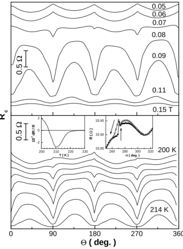
order phase transition character of the zero field transi-tion. In particular, crossing this branch, the resistance change is observed positive (although the overall mag-netoresistance is negative, see Fig. 3). Measurements of the angular dependence of the magnetoresistance along constant T and H intervals crossing T3D(H) bring
ad-ditional information (Fig. 7). The striking features of such results are: i) a large angular susceptibility of the transverse magnetoresistance develops at the crossing of the line along the a and b directions; ii) just below this line (at 200 K in Fig. 7), there is a two-fold periodicity (we have checked, deliberately tilting the crystal and ob-serving no qualitative change in the Rc(θ) behavior, that
this cannot be due to the sample misalignment), and the peaks in angular susceptibility are hysteretic.
We propose that a magnetic ordering transition along c-axis may account for these observations. Indeed, such a transition would have a large effect on the transverse re-sistivity by the virtue of the mechanism described above. Then, ferromagnetic domains being linked to the possibil-ity to order magnetism from plane to plane, it is natural to expect their signature to show up below this transition, as well as some potential a/b unbalance due to
inequiva-4
lent domains. Finally, the susceptibility to the magnetic field at the transition should be the larger when the field is applied along one of the two possible directions for the ferromagnetic moment. The scenario in Ref. 15 proposed that a c-axis field induces an in-plane rotation of the spins, while at a constant angle from the c-axis. If so, we expect a reduction of the ferromagnetic component with the applied field. It is then possible that this re-duction favors magnetic decoupling along the c-axis. To the credit of our picture, preliminary measurements on Sr2−xLaxIrO4indicate – beside the known TN decrease –
that the T3D(H) line is suppressed in zero field (i.e. the
positive transverse resistivity anomaly is replaced by the negative one, as in an applied field). This suggests that disorder may also contribute to weaken the c-axis mag-netic ordering, just as for Sr2Ir1−xRhx>0.03O4exhibits a
modified c-axis magnetic ordering to the so-called ’AF-II’ phase with ferromagnetic inter-plane order[20]. The observation of a smooth crossover distinct from the sharp transition to the 3D ordered state seems also to
corrobo-rate the one that the in-plane magnetic fluctuation corre-lation length decreases above TN much less rapidly than
the out-of-plane one, a feature interpreted as the conse-quence of a two-dimensional S= 1/2 quantum Heisenberg model[19].
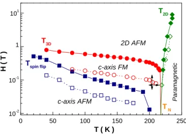
The overall picture would then be the following: in zero field, we observe a single transition temperature at TN
were 3D magnetic order establishes. Applying a magnetic field splits the transition into two branches: a near ver-tical branch at T > TN at which AF order is established
in the plane, and a low temperature one, where a long range c-axis magnetic order is established. A second line in the ordered phase delimits field-induced ferromagnetic interplane ordering. We propose that magnetotransport is influenced strongly by direct spin reorientation effects, in addition to bond reorientation ones. Our data clearly contradicts the general belief that there would be no in-fluence of the magnetic state on the transport properties. We have proposed that this influence should be evaluated here considering hopping of the localized charge.
[1] B. J. Kim, Hosub Jin, S. J. Moon, J.-Y. Kim, B.-G. Park, C. S. Leem, Jaejun Yu, T.W. Noh, C. Kim, S.-J. Oh, J.-H. Park, V. Durairaj, G. Cao, and E. Rotenberg, Phys. Rev. Lett. 101, 076402 (2008).
[2] B. J. Kim, H. Ohsumi, T. Komesu, S. Sakai, T. Morita, H. Takagi and T. Arima, Science 323, 1329 (2009). [3] Feng Ye, Songxue Chi, Bryan C. Chakoumakos, Jaime
A. Fernandez-Baca, Tongfei Qi, and G. Cao, Phys. Rev. B 87, 140406(R) (2013).
[4] M. K. Crawford, M. A. Subramanian, R. L. Harlow, J. A. Fernandez-Baca, Z. R. Wang, and D. C. Johnston, Phys. Rev. B 49, 9198 (1994).
[5] G. Jackeli and G. Khaliullin, Phys. Rev. Lett. 102, 017205 (2009).
[6] T. Thio, T. R. Thurston, N. W. Preyer, P. J. Picone, M. A. Kastner, H. P. Jenssen, D. R. Gabbe, C. Y. Chen, R. J. Birgeneau and Amnon Aharony, Phys. Rev. B 38, 905(R) (1988).
[7] G. Cao, J. Bolivar, S. McCall, J. E. Crow, and R. P. Guertin, Phys. Rev. B 57, R11039(R) (1998).
[8] Vamshi M. Katukuri, Hermann Stoll, Jeroen van den Brink, and Liviu Hozoi, Phys. Rev. B 85, 220402(R) (2012).
[9] Fa Wang and T. Senthil, Phys. Rev. Lett. 106, 136402 (2011).
[10] M. Moretti Sala, S. Boseggia, D. F. McMorrow, and G. Monaco, Phys. Rev. Lett. 112, 026403 (2014).
[11] C. Martins, M. Aichhorn, L. Vaugier, and S. Biermann, Phys. Rev. Lett. 107, 266404 (2011).
[12] R. Arita, J. Kune˘s, A.V. Kozhevnikov, A. G. Eguiluz and M. Imada, Phys. Rev. Lett. 108, 086403 (2012). [13] N. S. Kini, A. M. Strydom, H. S. Jeevan, C. Geibel and
S. Ramakrishnan, J. Phys.: Condens. Matter 18, 8205 (2006).
[14] D. Hsieh, F. Mahmood, D. H. Torchinsky, G. Cao, and N. Gedik, Phys. rev. B 86, 035128 (2012).
[15] M. Ge, T. F. Qi, O. B. Korneta, D. E. De Long, P. Schlottmann, W. P. Crummett, and G. Cao, Phys. Rev.
200 220 240 260 -5 0 5 T 2D T 3D T N 0.8 T 2 T 9 T 0.2 T 0.4 T H = 0 1 0 2 ( R c R c 0 ) / R c 0 T ( K ) 150 200 250 1.2 1.4 1.6 1.8 0 T 9 T T ( K ) l o g ( R c ) 10-2 10-1 1 10 195 K ( TC - T ) / TC 1 0 2 ( R c Rc 0 ) / Rc 0
FIG. 1: c-axis resistance anomaly, as obtained subtracting a high temperature linear logarithmic resistance (dashed line in lower inset). Upper inset: scaling of the resistive anomaly. The magnetic field is applied along the c-axis.
B 84, 100402(R) (2011).
[16] S. Chikara, O. Korneta, W. P. Crummett, L. E. DeLong, P. Schlottmann, and G. Cao, Phys. Rev. B 80, 140407(R) (2009).
[17] Tineke Thio, C. Y. Chen, B. S. Freer, D. R. Gabbe, H. P. Jenssen, M. A. Kastner, P. J. Picone, N. W. Preyer and R. J. Birgeneau, Phys. Rev. B 41, 231 (1990). [18] L. Shekhtman, I. Ya. Korenblit and A. Aharony, Phys.
Rev. B 49, 7080 (1994).
[19] S. Fujiyama, H. Ohsumi, T. Komesu, J. Matsuno, B. J. Kim, M. Takata, T. Arima, and H. Takagi, Phys. Rev. Lett. 108, 247212 (2012).
[20] J. P. Clancy, A. Lupascu, H. Gretarsson, Z. Islam, Y. F. Hu, D. Casa, C. S. Nelson, S. C. LaMarra, G. Cao and Young-June Kim, Phys. Rev. B 89, 054409 (2014).
0 50 100 150 200 250 10-2 10-1 1 101 2D AFM c-axis FM c-axis AFM Pa ra m a g n e ti c Tspin flip T3D T2D T N H ( T ) T ( K )
FIG. 2: Phase diagram for the transverse resistivity, as ob-tained from the data in Fig. 3 (squares and circles) and the onset in Fig. 1 (diamonds). Filled symbols are for field ap-plied along the c-axis; open ones, in the a-b plane. TN is
the zero field transition temperature, as given by the data in Fig. 1.
6 0 0.1 0.2 -100 -50 0
T
sfT
sfT
3DT
3DH // c
H
⊥
c
60 80 100 115 125 135 145 155 165 175 185 195 205 210 40 60 80 100 115 125 135 145 165 175 200 195 205 210 K 1 0 2 [ R c (H ) - Rc (0 ) ] / Rc (0 ) 0 2 4 6 8 -50 0 220 K H ( T )FIG. 3: c-axis magnetoresistance, for field along (lower panel) and perpendicular to c-axis (upper). Symbols mark the char-acteristic fields in Fig. 2. (curves have been shifted from their H= 0 zero value, for clarity)
200 210 220 230 10-2 10-1 1 180 90 180 0 180 0
T
N H ( T ) T ( K )FIG. 4: Torque (Γ) angular dependence at typical locations in the H -T plane. Magnetic field is rotated in the a(b)-c plane. The angle is the one from the c-axis. Symbols are from Fig. 2.
210 220 230 240 250 0 2 4 6
0.2 T
H = 4 T
1 0 4 R c , 4 ( 2 ) / R c (H = 0 )T ( K )
0 2 4 6 1 0 2 ( R c R c 0 ) / R c 0 0 90 180 270 360 5 1 0 4 210 K 215 220 225 Θ ( deg. )FIG. 5: Upper panel: angular dependence of the magnetore-sistance (in-plane field H = 0.2 T); θ is the angle between a(b) and the magnetic field. Lower panel: Symbols: four-fold and two-fold (dotted line) components of the angular c-axis magnetoresistance (left scale). Full line: zero field c-axis re-sistance anomaly, as in Fig. 1
FIG. 6: With ferromagnetic coupling of the in-plane magnetic moment, as shown (green arrow), transverse hopping occurs within a magnetic sublattice of equivalent Ir, 1-5-3. Antiferro-magnetic coupling is obtained reversing the spins in one layer, and hopping within a sublattice occurs between inequivalent 1-2-4.
8 0 90 180 270 360 0 .5 Ω 0 .5 Ω 200 K 214 K
R
c Θ( deg. )
200 210 220 230 -2 0 2 T ( K ) 1 0 2 d R / R 260 280 300 320 33.85 33.90 33.95 R ( Ω ) Θ ( deg. ) 0.06 0.07 0.08 0.09 0.11 0.15 T 0.05FIG. 7: Angular dependence of the magnetoresistance along the two segments in Fig. 2 (field in the a-b plane). Upper panel: T = 204 K. Lower panel: H = 0.07 T (T varies in steps of 2 K); left inset: resistance anomaly in zero field, obtained as in Fig. 1; right inset: occurrence of a uniaxial hysteretic feature (T = 200 K).