Publisher’s version / Version de l'éditeur:
Journal of Materials Research, 6, 5, pp. 957-963, 1991-05
READ THESE TERMS AND CONDITIONS CAREFULLY BEFORE USING THIS WEBSITE. https://nrc-publications.canada.ca/eng/copyright
Vous avez des questions? Nous pouvons vous aider. Pour communiquer directement avec un auteur, consultez la première page de la revue dans laquelle son article a été publié afin de trouver ses coordonnées. Si vous n’arrivez pas à les repérer, communiquez avec nous à PublicationsArchive-ArchivesPublications@nrc-cnrc.gc.ca.
Questions? Contact the NRC Publications Archive team at
PublicationsArchive-ArchivesPublications@nrc-cnrc.gc.ca. If you wish to email the authors directly, please see the first page of the publication for their contact information.
NRC Publications Archive
Archives des publications du CNRC
This publication could be one of several versions: author’s original, accepted manuscript or the publisher’s version. / La version de cette publication peut être l’une des suivantes : la version prépublication de l’auteur, la version acceptée du manuscrit ou la version de l’éditeur.
For the publisher’s version, please access the DOI link below./ Pour consulter la version de l’éditeur, utilisez le lien DOI ci-dessous.
https://doi.org/10.1557/JMR.1991.0957
Access and use of this website and the material on it are subject to the Terms and Conditions set forth at
Plastic deformation and fracture behavior of a Fe-modified Al3 Ti-base
L12 intermetallic alloy
Hu, Gengxiang; Chen, Shipu; Wu, Xiaohua; Chen, Xiaofu
https://publications-cnrc.canada.ca/fra/droits
L’accès à ce site Web et l’utilisation de son contenu sont assujettis aux conditions présentées dans le site
LISEZ CES CONDITIONS ATTENTIVEMENT AVANT D’UTILISER CE SITE WEB.
NRC Publications Record / Notice d'Archives des publications de CNRC:
https://nrc-publications.canada.ca/eng/view/object/?id=45bb1bc5-1c15-4ae0-b4fb-9ec1b62ba257 https://publications-cnrc.canada.ca/fra/voir/objet/?id=45bb1bc5-1c15-4ae0-b4fb-9ec1b62ba257
Hu Gengxiang, Chen Shipu, Wu Xiaohua, and Chen Xiaofu
Department of Materials Science, Shanghai Jiao Tong University, Shanghai 200030, People's Republic of China
(Received 1 October 1990; accepted 16 January 1991)
The microstructure of the ordered intermetallic alloy with a nominal composition of Al66Fe9Ti24 is nearly single-phase Ll2 structure, with a few second phase agglomerates at
some grain corners. Room temperature compression tests showed that this material exhibits a plastic strain of about 11% at fracture. Final fracture of the compression specimens occurred by a shear-off process along a surface oriented about 45 degrees to the compression axis. Fractographic analysis revealed that the fracture is transcrystalline and the fracture mode is mainly quasicleavage plus tearing. Transmission electron microscopy (TEM) was used to explore its deformation mechanisms. The dislocation density was low after homogenization, but is greatly increased during deformation. The deformation mode was found to be (110) {111} slip instead of twinning as in Al3Ti. The
a(110) superdislocations dissociated into two partials of a/3(211)-type, bounding a superlattice intrinsic stacking fault (SISF) on the {111} slip plane.
I. INTRODUCTION
The ordered intermetallic Al3Ti exhibits some
at-tractive characteristics such as low density (3.4 g/cc) and high oxidation resistance, but is extremely brittle at room temperature. Since Al3Ti crystallizes into the
te-tragonal DO22 structure,_the major deformation mode was identified as (111) [112] twinning, and slip occurred only at high temperatures.1
It is encouraging that the DO22 Al3Ti can be changed
to the cubic Ll2 ordered structure by replacing some
amounts of Al with Cu, Ni, or Fe,2"4 and also Mn and Cr, as has been reported recently.5 Since the Ll2
struc-ture is highly symmetrical and may have a sufficient number of slip systems for homogeneous deformation, it is expected that the ductility of modified Al3Ti-base
al-loys will be greatly improved. This has attracted much attention and has led to a considerable amount of re-search in recent years. However, the results reported did not come up to the expectation. For instance, the Al3Ti alloys having Ll2 structure with Fe or Ni addition
were also brittle and the fracture mode was still cleav-age.4'6 Therefore, further investigations aimed toward understanding the deformation behavior and the causes of low ductility of the Ll2-type Al3Ti alloy are necessary.
In this paper, an Ll2 intermetallic alloy with
com-position near Al66Fe9Ti24 (at. %) was studied. This
poly-crystalline material shows appreciable compression ductility at room temperature. To understand the defor-mation behavior, a microstructural characterization of this ordered alloy was carried out and the deformation mode was studied by TEM analysis.
II. EXPERIMENTAL
The Al3Ti-based alloy with nominal composition
Al66Fe9Ti24 was prepared by arc-melting in argon with
a nonconsumable tungsten electrode on a water-cooled copper hearth. The cast buttons were homogenized at 1373 K for 60 h to eliminate nonequilibrium segregation.
Compression specimens with dimensions 4 x 4 x 7 mm were cut from the homogenized ingots. Tests were carried out in a Shimadzu DCS-25T machine. A crosshead speed of 0.05 mm/min was used, yielding a nominal strain rate of about 0.007/min. Some of the specimens were compressed only to a small amount of plastic strain (below 3%) for the purpose of exploring the deformation mechanisms.
Crystal structure determination and phase analysis were done by x-ray and electron diffraction methods. Microstructures and fractographic morphologies were examined using optical and scanning electron micros-copy (OM and SEM). Chemical microanalysis was con-ducted with energy dispersive spectrometry (EDS) in the scanning electron microscope.
Thin foil specimens were prepared by twin jet pol-ishing in a mixture of perchloric acid, butanol, and methanol (30:175:300 by volume) at 233 K and were examined by transmission electron microscopy (TEM) for the study of deformation substructure.
III. RESULTS AND DISCUSSION A. Microstructures
Indexing of the x-ray diffraction patterns of the Al66Fe9Ti24 alloy in either as-cast or homogenized con-J. Mater. Res., Vol. 6, No. 5, May 1991 1991 Materials Research Society 957
G. Hu etal.: Fe-modified AI3Ti-base L12 intermetallic alloy
ditions indicated that all the resolvable peaks are iden-tified with the fundamental and superlattice reflections of the ordered Ll2 structure, in contrast with the DO22
of the unalloyed Al3Ti compound. Electron diffraction
patterns obtained by TEM from the thin foils also veri-fied the Ll2 structure.
The optical micrograph [Fig. l(a)] of the as-cast alloy exhibits fine dendritic structure with second phase in the interdendritic regions. The dendritic struc-ture was eliminated after 1373 K homogenization. However, the second phase could not be removed com-pletely after such a treatment, agglomerates with irreg-ular shapes occurring mainly at grain corners, as shown in Fig. l(b).
As mentioned above, x-ray diffraction spectra did not reveal the existence of a second constituent in this alloy. This is due to their small quantities, which can-not produce detectable intensities of reflected x-rays.
The presence of an fee Al2TiX phase has been
veri-fied in Al-Ti-X systems by several workers, where X = Fe,7 Ni,8 or Mn.9 The second phase existing in the present alloy may also be of the Al2TiFe-type, although
the EDS microanalysis results performed in SEM did not fit with the equal amounts of Ti and Fe.
B. Deformation behavior
1. Compressive plasticity
The results of compression tests at room tempera-ture are summarized in Table I, and a typical load-deformation curve is shown in Fig. 2.
The plastic strains ef listed here were calculated
from the crosshead displacement recorded by the test-ing machine after fracture. In fact, the crosshead dis-placement not only resulted from the elastic and plastic strains of the compressed specimen, but is also due to the closing of initial gaps and the deformation of the
T A B L E I. C o m p r e s s i v e p r o p e r t i e s of t h e Al66Fe9Ti24 alloy at r o o m t e m p e r a t u r e ( s p e c i m e n : 4 x 4 x 7 m m ) . No. 1 2 3 4 Average Ultimate strength crmax, MPa 486 405 510 481 471 ± 45 Yield strength cro.2, MPa 286 272 258 240 264 ± 20 Plastic e/ (recorded) 14 12 15 16 14 ± 2 strain, % ep (corrected) 10 9 12 13 11 ± 2
entire loading system. Therefore, a correction has been made to obtain the actual plastic strain at fracture, ep,
of the tested specimens, as shown in Table I. It can be seen that the Al66Fe9Ti24 alloy exhibits an appreciable
compressive ductility of about 11% at room temperature. The strain distribution in the compressed specimen is inhomogeneous, which was observed with the naked eye by the flow markings in relief on the specimen sur-faces. As the alloy is polycrystalline, these flow mark-ings also indicate that slip propagated from one grain to the next throughout a region extending right across the specimen. To achieve such deformation, a mini-mum of five independent slip systems must be acti-vated. Therefore, the good compression ductility of the Unstructured Al66Fe9Ti24 alloy is attributed to a
suf-ficient number of slip systems operating during defor-mation. Final fracture of the compression specimens occurred by a shear-off process along a surface oriented about 45 degrees to the compression axis. An example of the fractured specimens is shown in Fig. 3; an origi-nal specimen is also shown for comparison.
Fractographic analyses showed that the fracture is transcrystalline in nature and the fracture mode is
a . : * " • . . b
FIG. 1. Microstructures of the as-cast (a) and homogenized (b) Al66Fe<>Ti24 alloy.
958 J. Mater. Res., Vol. 6, No. 5, May 1991
DEFORMATION
FIG. 2. Typical load-deformation curve of the AlaFe9Ti24 alloy
tested under compression at room temperature.
mainly quasicleavage10 plus tearing. An example of the fracture surface revealed by SEM is shown in Fig. 4(a), where the microscopic irregularities of quasicleavage surface and the linking tear ridges are apparent. A close examination at high magnification revealed that the quasicleavage regions are associated with dense steps of slip bands and curved subsurfaces [Fig. 4(b)]. These features together with the tear ridges observed in Fig. 4(a) illustrate that these regions were evidently de-formed before fracture.
4 nim
2. Dislocation substructures
In order to explore the deformation mechanisms, dislocation configurations in the Ll2-structured A16
6-Fe9Ti24 alloy compressed at room temperature have
been analyzed by TEM. The general view is shown in Fig. 5. In contrast with the few straight free dislocations observed in the homogenized alloy (Fig. 6), the disloca-tion density is greatly increased after deformadisloca-tion. The moving dislocations introduced through deformation were locally pinned, as indicated by the bowing-out. They appeared to be in pairs, showing that the (101) superdislocations dissociated into two partials, as con-firmed by {220}-type reflections [Fig. 5(b)]. Using the weak beam technique, neither of the two partials was revealed to be further dissociated. No evidence of twin-ning was found. These results confirmed that disloca-tion slip must be the main mode of deformadisloca-tion of the present alloy, instead of twinning, as in the DO22-type
Al3Ti which has been shown to be extremely brittle at
room temperature.
It is known that three kinds of planar faults occur on {111} planes of the Ll2 structure: antiphase boundary
(APB), geometrical stacking fault (GSF, also called superlattice intrinsic stacking fault, SISF), and complex stacking fault (CSF), with displacement vectors 1/2(110), 1/3(112), and 1/6(112), respectively. The possible disso-ciation of an a[101] superdislocation in the Ll2 structure
is assumed to be any of three schemes—for instance, in the (111) plane:
1. [T01] > 1/6[II2] + CSF + 1/6[211] + APB
2. [101]
CSF
l/2[101] + APB + l/2[101]
FIG. 3. Fractured (left) and original (right) specimens of the Al66Fe9Ti24 alloy in compression tests.
3. [101] > 1/3[211] + SISF + 1/3[112]
They have already been observed in different Ll2
alloys.11"16
In this study, superdislocation splitting into two partials labeled 1 and 2 in Fig. 5(b) was chosen to iden-tify the configuration of dislocation dissociations and the nature of the planar fault bounded by such partials in detail.
Figure 7 is the TEM micrographs taken from the same particularly interesting region labeled in Fig. 5(b), but at higher magnification. Trace analysis indicated that the extended superdislocation is lying in the (ill) plane and the labeled partials bounding the fault are parallel to the [lOl] direction. Figure 7(a) shows a near (110) projection of the dislocation structure j n which the fault plane seems to be perpendicular to [111]. The par-tials 1 and 2 are along the trace [101], the intersection of (ill) and (111) planes, of which the latter is the pro-jective plane of Fig. 7(b). These observations suggest that the dissociated superdislocation may have a total Burgers vector of a[101] (or a[101]).
G. Hu etal.: Fe-modified AI3Ti-base L12 intermetallic alloy
•*H$.«ME*"W
FIG. 4. SEM fractographs of the frac-ture surface of the Al66Fe9Ti24 alloy.
891142 X 2 i § " * " i 5 § U B 8 9 1 1 4 ? 2iK¥ 020 \
022
.2 ... ^ . 0.FIG. 5. Dislocation structures of the Ll2-structured Al66Fe9Ti24 alloy deformed under compression at room temperature, (a) a =
418 MPa, e = 2.83%; (b) o- = 270 MPa, e = 1.52%.
Contrast analysis of the partial dislocations has been carried out by using different reflections. The in-visibility criteria for partial dislocations are g • b = 0,
±1/3.n It has also been shown that for s > 0, a partial is in contrast when g • b = +2/3, but out of contrast when g • b = -2/3.1 8 In the case of g • b = ±4/3, a partial becomes invisible as g • b is positive and the re-verse is true when it is negative.19 Figures 5(b) and 7(a)-7(f) are some selected TEM micrographs, all of which were taken with the deviation parameter s > 0.
The fact that both partials 1 and 2 are not simulta-neously in contrast or out of contrast for all these re-flections used for Fig. 7 (sometimes one shows only weak residual contrast) confirmed that they must be of l/3(112)-type, and the dissociation of superdislocation a[101] would occur in the form of scheme 3. Table II lists the g • b values of the partials dissociated from an a[101] superdislocation in the (111) plane, together with
200
WB
FIG. 6. Weak beam TEM micrograph shows straight free a(101) dislocations in the undeformed Al66Fe9Ti24 alloy after
homogenization.
220
902
2
022
~
\
-\
•
131
\
2
' ' S fl V y i C ' / ' s " • • v i sFIG. 7. TEM micrographs of the partials labeled 1 and 2 [the same as in Fig. 5(b)] for contrast analysis. See text and Table II.
the observed results. It can now be concluded that the Burgers vector is a/3[2ll] for partial 1 and a/3[Tl2] for partial 2.
The intrinsic/extrinsic nature of the fault bounded by partials 1 and 2 has been determined using {111}-type reflections. Figure 8 was taken at a near (211) projection with s = 0, in which the fault plane (ill) is inclined to the surface of the foil. For a stacking fault on the (ill) plane, the displacement vector Rf is ±a/3[lll]. In the BF image with (111) reflection, Fig. 8(a), both fringes at
the intersections between the fault plane and the foil surfaces show dark contrast. When a CDF image with (111) reflection, Fig. 8(b), is observed, the first fringe in the left (top) is found to be bright and the contrast of the right-side (bottom) fringe remains dark.
A simple way to identify the nature of a stacking fault was proposed by Gevers et al.20 with a dark-field image only. For g = 111, which belongs to the so-called type B reflection, when placing the origin of the dif-fraction vector at the center of the fault, it has been
G. Hu etal.: Fe-modified AI3Ti-base L12 intermetallic alloy
TABLE II. Values of g • b for the possible Burgers vectors of the partials labeled 1 and 2 and the experimental observations of their visibilities. g 002 220 022 Oil 131 131 Partial 1 (6 = 1 Expt. obser. V R.C. I.V. V V V /3[211]) g-b + 2/3 - 2 / 3 0 + 2/3 +2/3 - 2 Partial 2 (b = : Expt. obser. I.V. V V I.V. I.V. I.V. 1/3[112]) g-b +4/3 - 4 / 3 +2 + 1/3 - 2 / 3 0 Fig. 7(a) 7(b) 7(c) 7(d) 7(e) 7(f)
V: visible; I.V.: invisible; R . C : residual contrast.
found that g points away from the bright outer fringe, i.e., toward the dark fringe at the right side in Fig. 8(b). This is the contrast feature expected from an intrinsic stacking fault.
The above observations lead us to conclude that the glide superdislocation with Burgers vector a[101] has dissociated into two superpartials of a/3(112)-type bounding a SISF in the (ill) plane:
[101] > l/3[2ll] + SISF + 1/3[T12]
that is, in the Al66Fe9Ti24 alloy the dislocation
dissocia-tion takes place in the mode of scheme 3.
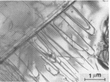
Furthermore, such an a(101) dislocation slip mecha-nism can be clearly seen in Fig. 9, which shows a planar array of slipping a[101] superdislocations in the (111) glide plane and each of them dissociated into two par-tials. Contrast analysis also delineated that the super-partials are of a/3(211)-type, bounding SISFs.
Figure 10 shows the elongated dislocation loops in the (111) plane multiplied from a subboundary. This microscopic feature resembles the TEM observations of Takeuchi et al.21 in deformed Ni3Ga Ll2 crystals, from
which they have suggested that the source dislocations are self-trapped by thermally activated locking of screw segments due to the Kear-Wilsdorf mechanism, and the anomalous temperature dependence of the strength can be ascribable to this hardening mechanism of (111) slip.
Different dissociation configurations of the super-dislocation have a strong influence on the deforma-tion of the Ll2 materials. It has been found2 that the
Al22Fe3Ti8 alloy shows anomalous increase of yield
stress both in the low temperature region with decreas-ing temperature and in the high temperature region with increasing temperature, which is similar to that in a group of Ll2 alloys such as Co3Ti. There has been no
appropriate mechanism proposed to explain such yield behavior. Liu et al.16 pointed out that the superdisloca-tion with SISF would be responsible for the anomalous increase of yield stress at low temperatures. Micro cross slip may also operate in such alloys. As evidence, the dipoles of the extended dislocations were observed in the present alloy, as shown in Fig. 5. Furthermore, it is noteworthy that more than one configuration of dislo-cation dissociation sometimes occurs in certain Ll2
structures. For instance, widely extended GSFs have been identified in deformed Ni3Ga22 and Ni3Al23 as a
result of the interaction of moving superdislocations with other lattice defects. It is not possible to affirm that the dissociation of scheme 3 is the unique mode for the alloy investigated here. These factors might lead to
i l l
BF
111 CDF
FIG. 8. Stacking fault bounded by the partials 1 and 2 as labeled in Figs. 5(b) and 7. See text for the details of analysis.
;
if
1
i r
J
FIG. 9. A row of «[101] superdislocation slipping in a (111) plane, dissociated into partials 1 and 2 of o/3(112)-type bounding SISFs.
V
FIG. 10. The elongated dislocation loops in (111) plane multiplied from a subboundary.
an explanation for the anomalous dependence of yield stress over the entire temperature range.
IV. CONCLUSIONS
(1) The Al3Ti-base intermetallic alloy with a
com-position near Al66Fe9Ti24 crystallizes into the Ll2
or-dered structure. The second phase presented is possibly of Al2TiFe-type.
(2) The Al3Ti-base alloy containing Fe exhibits
ap-preciable compressive ductility at room temperature. (3) The alloy investigated deforms by a slip process at room temperature. TEM study on the substructure of the deformed specimens indicated that the a[101] superdislocation dissociated into two superpartials bounding a SISF in the (111) glide plane, i.e.,
[T01] > l/3[2~Tl] + SISF
REFERENCES
*M. Yamaguchi, Y. Umakoshi, and T. Yamane, in
High-Tempera-ture Ordered Intermetallic Alloys, II, edited by N. S. Stoloff, C. C.
Koch, C.T. Liu, and O. Izumi (Mater. Res. Soc. Symp. Proc. 81, Pittsburgh, PA, 1987), p. 275.
2
K.S. Kumar and J.R. Pickens, Scripta Metall. 22, 1015 (1988).
3
J. Tarnacki and Y.W. Kim, Scripta Metall. 22, 329 (1988).
4
C. D. Turner, W. O. Powers, and J. A. Wert, Acta Metall. 23, 2635 (1989).
5
S. Zhang, J. P. Nic, and D. E. Mikkola, Scripta Metall. 24, 57 (1990).
6
E. P. George, W. D. Porter, H. M. Henson, W. C. Oliver, and B. F. Oliver, J. Mater. Res. 4, 78 (1989).
7
A. Seibold, Z. Metallic. 72, 712 (1981).
8
S. C. Huang, E. L. Hall, and M. F. X. Gigliotti, J. Mater. Res. 3, 1 (1988).
9
H. Mabuchi, K. Hirokawa, and Y. Nakayama, Scripta Metall. 23, 1761 (1989).
w
Metals Handbook, 9th ed. (ASM INTERNATIONAL, 1987),
Vol. 12, p. 20.
"S. M. L. Sastry and B. Ramaswami, Philos. Mag. 33, 375 (1976).
12
A. Korner and H. P. Karnthaler, Philos. Mag. A 52, 29 (1985).
13
K. Suzuki, M. Ichihara, and S. Takeuchi, Acta Metall. 27, 193 (1979).
14
R. J. Taunt and B. Ralph, Philos. Mag. 30, 1379 (1974).
15
L. M. Howe, M. Rainville, and E. M. Schulson, J. Nucl. Mater. 50, 139 (1974).
16
Y. Liu, T. Takasugi, O. Izumi, and T. Takahashi, Acta Metall. 36, 2959 (1988).
17
A. Howe and M. J. Whelan, Proc. Roy. Soc. A267, 206 (1962).
18
J. M. Silcock and W. J. Tunstall, Philos. Mag. 10, 361 (1962).
19
J. M. Oblak and B.H. Kear, in Electron Microscopy of Materials, edited by G. Thomas, R. M. Fulrath, and R. M. Fisher (Univer-sity of California Press, 1972), p. 566.
20
R. Gevers, A. Art, and S. Amelinckx, Physica Status Solidi 3, 1563 (1963).
21
S. Takeuchi, K. Suzuki, and M. Ichihara, Trans. JTM 20, 264 (1979).
22
H-r. Pak, T. Saburi, and S. Nenno, Scripta Metall. 10,1081 (1976).
23
I. Baker and E. M. Schulson, Physica Status Solidi A85, 481 (1984).


![FIG. 7. TEM micrographs of the partials labeled 1 and 2 [the same as in Fig. 5(b)] for contrast analysis](https://thumb-eu.123doks.com/thumbv2/123doknet/14256713.488831/6.864.65.800.129.881/fig-tem-micrographs-partials-labeled-fig-contrast-analysis.webp)