Development of Control System to Automate the
PCB Pin Insertion Process
by
Rejin Isaac
B.Tech., National Institute of Technology Karnataka (2010)
Submitted to the Department of Mechanical Engineering
in partial fulfillment of the requirements for the degree of
Master of Engineering in Manufacturing
at the
MASSACHUSETTS INSTITUTE OF TECHNOLOGY
September 2012
©
Rejin Isaac, MMXII. All rights reserved.
The author hereby grants to MIT permission to reproduce and to
distribute publicly paper and electronic copies of this thesis document
in whole or in part in any medium now known or hereafter created.
Author ...
.
...
Departmehjt of Mechanical Engineering
August 21, 2012
Certified by...
i
bDavid
E. Hardt
Ralph E. and Eloise F. Cross Professor of Mechanical Engineering
Thesis Supervisor
A ccepted by ...
...
David E. Hardt
Chairman, Department Committee on Graduate Studies
Development of Control System to Automate the PCB Pin
Insertion Process
by
Rejin Isaac
Submitted to the Department of Mechanical Engineering on August 21, 2012, in partial fulfillment of the
requirements for the degree of Master of Engineering in Manufacturing
Abstract
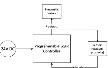
This thesis describes the development of the control system that runs the automated pin insertion machine in a surface mount technology assembly line. The control system is divided into 2 subsystems viz. pin sorting and pin insertion. The detailed design of the control system and its components is discussed, along with the program-ming of the Programmable Logic Controller for both subsystems. The development of the machine vision application used to sort the right pin types is described, with an emphasis on the image processing tools used. Applicability and robustness of these tools in the context of the pin insertion machine is described. The developed application can capture images and process them in 92 ms, significantly lower than the maximum allowable time of 500 ms. The vision system could totally eliminate the incidence of a wrong pin being passed on to the insertion head. Among the right pins, 98% of the right pins in the right orientation and 100% the pins in the wrong orientation were detected.
Thesis Supervisor: David E. Hardt
Acknowledgments
This thesis is the result of the efforts and contributions of various people to whom I would like to express my utmost gratitude and thanks.
My team mates, Daniel Cook and Michelle Chang, whose skills and hard work
made this a successful project. It was a pleasure working with you.
Lennart Pitzele, our supervisor at SynQor for providing me with invaluable advice, resources and support. Under your mentorship, I have learned a lot about manufac-turing automation and system design. Thank you for making this project a great learning experience.
Prof. David Hardt, our advisor for your directions, suggestions and guidance throughout this project. I'm sure your ideas, advice and experiences will be useful throughout my career.
Jennifer Craig, our writing advisor, for reviewing the progress and helping me structure this thesis.
My parents and friends, for their constant support and inspiration throughout the
Contents
1 Introduction 19 1.1 Motivation . . . . 20 1.2 Objectives . . . . 21 1.3 Scop e . . . . 21 1.4 Work Distribution. . . . . 22 2 System Overview 23 2 .1 P in s . . . . 23 2.1.1 Functionality . . . . 242.1.2 Project Pin Specifications . . . . 24
2.2 Existing Pinning Methods . . . . 25
2.2.1 Manual Pinning . . . . 26
2.2.2 Automated Pinning-Flexible Automation . . . . 27
2.2.3 Automated Pinning-Specialized Automation . . . . 28
2.3 Developed Solution . . . . 29
2.3.1 Overall Pinning Process/Final Design . . . . 30
2.3.2 System Components . . . . 32 3 Automation 35 3.1 Defining Automation . . . . 35 3.2 Brief History . . . . 36 3.3 Dynamics/Configurations . . . . 37 3.4 Economics of Automation . . . . 40
3.5 State of the Art . . . .
3.5.1 Machine Vision . . . .
3.5.2 Robotic Improvements . . . .
4 Machine Vision Systems: A Background
4.1 Overview.
4.2 Commonly Used Tools . . . . 4.2.1 Pattern Recognition . 4.2.2 Statistical Method . 4.2.3 Edge Detection . . . . 4.3 Illumination . . . . 4.3.1 Desirable Properties of an 4.3.2 Effect of Ambient Light 4.3.3 Types of Lights Available 4.3.4 Light Emitting Diodes 4.3.5 Illumination Techniques
Illumination
5 Control System Design
5.1 O verview . . . ... . . . .
5.2 Components . . . .
5.2.1 Pneumatic Valves . . . .
5.2.2 Pneumatic rotary actuators . . . . .
5.2.3 Stepper Motors . . . . 5.2.4 Programming the stepper motor . . . 5.2.5 Machine Vision System . . . .
5.2.6 Programmable Logic Controller . . . 5.2.7 Other Components . . . .
5.3 Integrating Machine Vision into the System 5.4 PLC Programming . . . .
5.4.1 5.4.2
Problems with QuickStep Programming L Pin Sorting . . . . System . . . . . . . . . . . . anguage. . . . . 41 41 43 45 45 47 47 48 48 49 49 49 50 51 51 54 54 55 55 58 59 60 61 62 62 63 64 65 66
5.4.3 Pin Insertion
6 Machine Vision Application Development 6.1 Existing System . . . .
6.1.1 Festo Checkbox Camera . .
6.1.2 Problems with the Checkbox
6.2 Requirements of a Vision System .
6.3 Lighting and Illumination . . . . .
6.3.1 Selection . . . .
6.3.2 Intensity . . . .
6.3.3 Effect of Ambient Light 6.3.4 Setting the shutter speed 6.4 Application Development . . . .
6.4.1 Unique identifiers of a Pin . 6.4.2 Tools Used . . . . 6.4.3 Flowchart Design . . . .
System
7 Testing and Results
7.1 Performance of the Machine Vision System . . . .
7.1.1 Setting Tolerances in the Vision Application . . . .
7.1.2 Robustness of the Pattern Match Tool . . . .
7.1.3 Problems with Edge Detection Tool . . . .
7.2 Modified Vision Application . . . .
7.2.1 Results of the Modified Program . . . . 7.2.2 Limitations of the Modified Program . . . .
7.2.3 Processing Time of the Vision Application . . . .
7.3 Pin Sorting Program . . . . 7.4 Pin Insertion Program . . . .
8 Conclusions and Future Work
8.1 C onclusions . . . . 76 76 76 77 77 78 78 79 80 82 82 82 82 84 90 90 90 93 95 98 100 101 102 102 102 103 103 71
8.2 Future W ork . . . 104
A Tables 107
A. 1 Pattern Match Percentage of Right pins in the Right Orientation . 107
A.2 Pattern Match for Pins in the Opposite Orientation . . . 110 A.3 Data for setting dimensional tolerance on the vision system . . . 111
A.4 Data from the modified vision application . . . 114
B PLC Programs 119
B.1 Pin Sorting Program . . . 119 B.2 Pin Insertion Program . . . 144
List of Figures
1-1 SM T Line Schematic . . . . 20
1-2 CAD rendering of pin . . . . 20
2-1 Typical maximum 0.040 pin dimensions (inches) . . . . 23
2-2 Pins pressed into a PCB . . . . 24
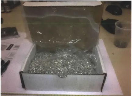
2-3 Pins are delivered to SynQor in a loose state in boxes from the manu-facturing com pany . . . . 25
2-4 Arbor Press used for manual pinning. The head of the arbor press has a collet on it to hold the pin that is attached to vacuum pressure. The vacuum pressure holds the pin in the collet and prevents it from falling o u t. . . . . 26
2-5 Dual-gantry pinning system . . . . 28
2-6 The vibratory bowls of this pinning system can be seen atop the ma-chine enclosure. These bowl feeders send pins to the insertion head inside of the m achine . . . . 29
2-7 Pinning Process Diagram . . . . 30
2-8 Magazine used to interface between sorting and insertion process . . . 31
3-1 Typical SCARA robot with work envelope shaded in grey [10] . . . . 38
3-2 Typical articulated arm robot with work envelope shaded in grey [11] 38 3-3 Typical gantry robot [12] . . . . 38
3-4 Cost of robotics versus manufacturing labor [14] . . . . 40
3-5 6 axes robot integrated with machine vision used in solar cell manu-facturing [22] . . . . 43
3-6 Adept Quattro parallel configuration robot . . . .4
4-1 A simple block diagram for a typical vision system operation [26] . . 46
4-2 Structural features for the number 5, a horizontal and vertical line, and a curve [28] . . . . 47
4-3 One dimensional edge profiles [26] . . . . 48
4-4 Nyloc Nuts. Left: Imaged with a UV ring light, but flooded with red 660 nm ambient light. The goal is to determine nylon presence
/
absence. Given the large ambient contribution, it is difficult to get sufficient contrast from the relatively low-yield blue fluoresced light from the sample. Right: Same lighting, except a 510 nm short pass filter was installed on the camera lens, effectively blocking the red ambient light and allowing the blue 450 nm light to pass. [27] . . . . 504-5 (a) Backlight (b) Diffuse Illuminator with central viewing (c) Coaxial illumination (d) Omni direction light source (e) Ring light (projects forwards) (f) Ring light (projects inwards) (g) Ring light (projects both inwards and outwards) (h) Spot light [25] . . . . 51
4-6 One dimensional edge profiles [26] . . . . 52
4-7 Dome shaped front lighting . . . . 52
4-8 O n-axis lighting . . . . 52
4-9 One dimensional edge profiles [26] . . . . 53
4-10 Partial bright field illumination [27] . . . . 53
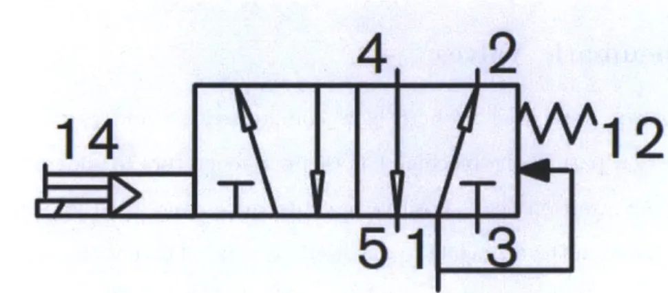
5-1 Festo MYH-5/2-2.3-L-LED Solenoid Valve . . . . 55
5-2 Symbol of a solenoid actuated 5/2 DCV with manual over-ride. On energizing the solenoid, compressed air flows from port 1 to port 4 [31] 56 5-3 Festo VN-05-H-T3-PQ2-VQ2-RQ2 vacuum generator. Compressed air flows in-line from port 1 to port 3, creating vacuum at port 2 [34] . . 56
5-4 Festo VAD-M-I vacuum generator. It has 2 solenoids, one for com-pressed air and the other for vacuum [33] . . . . 57
5-5 Pneumatic schematic of the VAD-M-I vacuum generator. When solenoid A is energized, there is compressed air at port 2 and vacuum when
solenoid B is energized[33] . . . .
5-6 SMC Pneumatic rotary actuator
[35]
. . . . 5-7 Operation principle of a rotary actuator [36] . . . . 5-8 Oriental DG-130 Motors Hollow Rotary Actuator with a stepper motorand the drive[37] . . . .
5-9 Pinion and gear based power transfer mechanism from the stepper
motor to the output table [37] . . . .
5-10 Keyence XG-7502P Machine Vision System [18] . . . . 5-11 Control Technology Corporation Blue Fusion 5220 Controller . . . . . 5-12 Wiring diagram to connect the Keyence system to the CTC controler
to enable external camera triggering [18] . . . .
5-13 Wiring diagram to connect the Keyence system to the CTC controller
to obtain the results from the Keyence system [18] . . . . 5-14 Overview of the connections in the pin sorting program . . . .
5-15 Top view of the pin sorting mechanism. The pins are loaded onto the
rotating wheel from the bowl feeder at Station 1. The wheel rotates in the clockwise direction. The camera is at Station 3. Depending on the output from the camera, the pins get re-oriented, loaded into a
magazine or rejected from the system . . . .
5-16 Schematic of the pin sorting program . . . . 5-17 Overview of the connections of the pin sorting machine 5-18 Flowchart of the pin insertion program . . . . 5-19 Pneumatic schematic of the pin insertion process[3] 5-20 Section view showing how the pin escapement extends
delivery tube to the insertion tube [3] . . . .
5-21 Section view showing how the pin escapement extends
delivery tube to the insertion tube [3] . . . .
from the pin
from the pin
57 58 58 59 60 61 62 63 64 66 . . . . 67 . . . . 68 . . . . 71 . . . . 72 . . . . 73 74 74
6-1 Fest CHB Checkbox camera . . . . 76 6-2 Two images of a 0.040" pin captured by the Checkbox at 2 different
instances . . . . 77 6-3 Image of a pin illuminated using a back lighting system. A columnate
filter has been placed on the back lighting system . . . . 79
6-4 Images of a .040" diameter pin in the rotating wheel at different inten-sities. The best image is obtained at 4 % of the maximum intensity . 80 6-5 Images of a .040" diameter pin in the rotating wheel at different lighting
conditions. It can be clearly seen that the best image was produced
when front lighting was used in the absence of ambient light . . . . . 81
6-6 Flowchart developed using the Keyence Vision Terminal. Each block in the flowchart represents an image processing step . . . . 85 6-7 A successful pattern match; the vision system was able to find a pattern
that matched the top part of the pin . . . . ... . . . . 86 6-8 A failed pattern match; the vision system was unable to find a pattern
that matched the top part of the pin as the pin is in the wrong orientation 86
6-9 Edge detection using the Keyence vision system . . . . 87
7-1 Variation in the total length of the most commonly used pin as
mea-sured by the vision system. The red bar indicates a failed measurement. The tolerance on the total length was set between 0.430 and 0.440 inches 91
7-2 Variation in the length between the top edge and the lower edge of the collar the most commonly used pin as measured by the vision system. The red bar indicates a failed measurement. The tolerance on the total
length was set between 0.220 and 0.230 inches . . . . 91
7-3 Variation in the diameter of the most commonly used pin as measured
by the vision system. The red bar indicates a failed measurement. The
7-4 Variation in the pattern match percentage of the most commonly used pin as measured by the vision system. The red bar indicates a failed pattern measurement. The pattern match cut-off percentage was set to 86% . .. . . . . .. . .. . . . . 93 7-5 Variation in the pattern match percentage of the most commonly used
pin in the inverted position as measured by the vision system. The red bar indicates a failed pattern measurement.14 of these had a pattern match percentage greater than 80; 2 passed. . . . . 94
7-6 A successful pattern match for a pin in the opposite orientation. This
pin is supposed to fail the pattern match test. The pattern match tool was not used in the application after obtaining such results on a repeated basis . . . . 94
7-7 The position of the pins before and after turning on the vacuum. On
turning the vacuum on, the pin raises from the collar and deviates from the vertical position . . . . 95 7-8 A successful pattern match; the vision system was able to find a pattern
that matched the top part of the pin . . . . 96 7-9 The collar of the pin has a darker edge than the slot of the recess on
converting it to binary . . . . 97 7-10 The vision system detected the right edge on converting the inspection
region to binary and increasing the image sensitivity . . . . 98 7-11 Modified flowchart without Pattern Match . . . . 99 7-12 Total length of the pins; every third pin is of the wrong type and the
vision system identifies it for all the pins used . . . . 100 7-13 Length of the pin from the observed top of the pin to the observed
lower edge of the collar. The red bar indicates a wrong measurement. This pin was of the right type in the right orientation. All oppositely oriented and wrong pin types were identified successfully . . . . 101
List of Tables
5.1 A typical data table. . . ... . . . . 70
A. 1 Pattern Match percentage of the right pin . . . . 107
A.2 Pattern match for wrongly oriented pins . . . . 110
A.3 Data for dimensional tolerance on the vision system . . . . 111
Chapter 1
Introduction
Surface Mount Technology (SMT) is a commonly used method in the electronics industry to assemble components on a printed circuit board (PCB). SMT allows both sides of the PCB to be populated with components, as opposed to traditional through-hole technology, where the leads of electronic components are inserted and soldered into holes in the PCB, which prevents the opposite side of the PCB from being used to mount components. With SMT, the PCB can then be physically smaller than PCBs produced through traditional through-hole methods. These advantages have led to SMT being adopted as the standard assembly method in the electronics industry.
A typical SMT assembly line is mostly automated with manual interaction limited
to loading and unloading of PCBs, and setting up machines for production runs. The assembly begins with the application of solder paste using a stainless steel stencil on the regions of the board where components are to be placed. Next, a pick and place machine places components on these regions. Modern day pick and place machines are capable of placing as high as 30,000 parts per hour. The boards then pass through a reflow oven, which melts the solder paste and fuses the components to the PCB. The opposite side is populated with parts using a similar procedure.
fNei 77
k7
Figure 1-1: SMT Line Schematic
Current enters and leaves the circuit through conductive input output (I/O) pins (see Figure 1) that are pressed into holes in the PCB. The pin insertion process takes place between the top and bottom side SMT assembly lines. These pins come in various lengths and diameters and can be inserted into the PCBs either manually or using an automated pinning machine.
Figure 1-2: CAD rendering of pin
1.1
Motivation
The advantages of an automated pin insertion machine are higher throughput, de-creased labor requirements and higher parts traceability. Although there are nu-merous automated pinning machines available in the market, customizing it to a
companys requirements can prove to be a hard task. Machines designed for pinning may not meet the reliability and throughput requirements that the company must
meet. Some of the common problems faced are reliably sorting pins from their loose state, jamming of pins, incorrect pin type being passed to the insertion head and right pin types being rejected by the system.
This thesis describes efforts in re-engineering and re-building the existing pinning machine at SynQor Inc., a designer and manufacturer of power supplies, located in Boxborough, MA.
1.2
Objectives
The project proposed to re-engineer a pre-existing pinning system into a production-ready system that is robust, cost effective, and flexible for unknown future pin types. The key objectives were as follows:
1. Develop a system which reliably sorts, orients, and inserts pins from a loose
bulk state into the PCBs;
2. Achieve the desired pinning rate of inserting 8 pins in 10 seconds;
3. Produce a system that is robust while remaining easy to repair and maintain;
4. Design flexibility into the machine for use with future product lines; and
5. Integrate the machine with the companys centralized tracking system to enable
parts traceability.
1.3
Scope
In this work, the project scope was narrowed to building an automated pinning ma-chine that could efficiently insert pins of one of most widely used pin types at the company. The focus was to design a working prototype of the pinning machine, so that the company could later convert it into a production-ready machine using the
same principles and mechanisms present in the prototype. The parts were designed to enable efficient interchanging of parts for various present and future pin types and sizes, while maintaining the same control system that integrated the entire system.
1.4
Work Distribution
Early in the design process, the conceptualized pinning system lent itself to three main sub-processes:
1. Sorting the pins from a loose bulk state to an oriented state;
2. Inserting the oriented pin into the PCB; and
3. Developing the vision and control systems necessary for the two previous tasks.
The initial development of each task was done as a group, but further work was split among the group members. Michelle Chang worked on the sorting of the pins from bulk to oriented state
[2].
The pin insertion system was developed by Daniel Cook[3]. The author of this thesis worked on developing the vision and control system
Chapter 2
System Overview
2.1
Pins
The main focus of this project is a specialized pin which is inserted into printed circuit boards (PCB). At its most basic, a pin is a cylindrical metal part with a collar. Figure 2 illustrates the maximum dimensions and features of a pin typical to the application. In total, there are 24 different pin types of varying diameters and lengths. The three diameters of pins used are 0.080, 0.062 and, the most commonly used, 0.040. Each of the three diameters has a selection of 8 different pin lengths depending on the application. 0.035 SQUARE SECTION A-A SCALE 2: 1 o 0 00 0 A 00.080 A -]0.0D A
2.1.1
Functionality
Pins are terminal components that are used to interface between the PCB and another product. They are attached to the boards with through-hole technology, that is, the pins are inserted into holes in the board and soldered in place. By connecting via a through-hole rather than a surface-mount pad, the pins can transfer an electronic signal through the thickness of the circuit board, useful for making interconnects on a multilayer board. [4]
Figure 2-2: Pins pressed into a PCB
These pins are used as interconnects between PCBs and other electronics external to the board they are mounted on. While one end of the pin is attached to the PCB, the other end may interface directly with the through holes of another circuit board or with receptacle terminals on another PCB or more flexible leads. [2]
2.1.2
Project Pin Specifications
The pins involved in this project are two-sided, cylindrical rods with a collar around the center. The insertion end of the pin is characterized by a square or hexagonal insertion head (see Figure 2). The interface end interfaces with the end users terminal connections. The length of the pin on either side of the collar is variable, and the total length of these pins ranges from about 0.3 inches to 0.5 inches.
SynQor uses three diameters of pins. This project focused on the most commonly used pin diameter 0.040. On 0.040 pins, the insertion head is square. The collar on these pins is 0.080 in diameter and 0.040 long with the exception of one pin with a
0.060 long collar, intended to offset the symmetry of the insertion end and interface
end lengths.
The pin is attached to the board in a two-step process. First, the pin is inserted into a PCB with an interference fit from the square or hexagonal insertion head. Second, the pin is soldered to the board. This project focused on the first part of pin attachment: the pin to board insertion process. In addition to the features noted, the pins also have two chamfers on the pin collars, which prevent solder cavities from forming during the soldering process. The pins are lead free and plated with tin. They are manufactured on screw machines and delivered in bulk in a loose state.
Figure 2-3: Pins are delivered to SynQor in a loose state in boxes from the manufac-turing company
2.2
Existing Pinning Methods
There are currently three methods for pinning a PCB at SynQor. One of the methods, manual pinning, relies on an operator to manipulate the pin and insert it into the board. The other two methods are two different approaches to automating the pinning
process. The three processes and the inefficiencies inherent to them are detailed in this section.
2.2.1
Manual Pinning
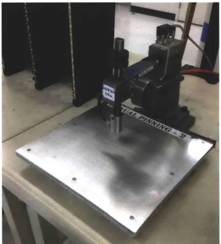
Pinning a board manually utilizes an arbor press with a special collet with negative pressure to retain the pin. To set up the process, the operator adjusts the depth stop on the arbor press by test inserting pins until the correct depth is achieved. Once this height is achieved and confirmed by measuring the depth, the operator locks the depth stop in place. At this point, the set up for the manual pinning process is complete.
Figure 2-4: Arbor Press used for manual pinning. The head of the arbor press has a collet on it to hold the pin that is attached to vacuum pressure. The vacuum pressure holds the pin in the collet and prevents it from falling out.
The operator takes a pin from the box of pins, inserts the head of the pin into the collet, and then locates the circuit board under the press according to a drawing
the details where each pin, and what type of pin, should be located. The board is populated with pins, and moved into a queue for the next process.
The operators scan each board into the SynQor production tracking system as they are pinning it, as well as the box that they are pulling pins from. Tracking pins in this manner provides some level of part traceability, but is prone to errors since often times there are multiple boxes of pins available for the operators to pick from.
Currently, the manual pinning process is run with two to three full time operators, for two shifts per day, depending on the workload. Manual pinning is labor intensive and costly. The goal is to reduce labor requirements with the process developed herein.
2.2.2
Automated Pinning-Flexible Automation
SynQor developed a pinning machine, working in conjunction with an outside com-pany in the early 2000s. The idea was to develop a process that allowed an operator to load up to 8 different pin types in vibratory bowls and have the machine feed pins, orient them, and then send them to an insertion machine to be inserted into the board without operator intervention.
The system works by feeding the pins by means of a vibratory bowl feeder to a conveyor. The conveyor transports the pins past a line-scan camera where an image is developed from the slices that the camera takes. From the image that the system builds, it analyzes the pin and determines if it is the correct pin, and if it is in the correct orientation. Downstream from the camera, an arm picks up the pin and reorients it (if necessary), then sends it through a tube by means of compressed air to the insertion robot. The robot picks up the pin and positions it at the correct point over the PCB and presses the pin to the correct depth.
ligure 2-b: Dual-gantry pinning system
This machine was used in production briefly when they first purchased it, but it was prone to failures. The machine struggled to deliver pins reliably to the insertion robot. There were issues with pins jamming at certain points in the system - fre-quently in the tube that delivered pins from the sorting mechanism to the insertion robot. The sorting mechanism was often not able to identify and re-orient pins fast enough to keep up with the pace set by the insertion robot. This problem often led to the insertion robot sitting idle while it waited for a pin.
The positioning system (a dual-gantry Cartesian robot see section 3.3) from this machine, as well as the production system interface (barcode scanning, board programming) will be re-used in the present project in its pre-existing form, with little modification.
2.2.3
Automated Pinning-Specialized Automation
Another pinning process was developed by SynQor with a different outside company. This system, decidedly less flexible in terms of the variety of pins it can handle, as well as how it handles faults, employs vibratory bowl feeders to feed and orient the pins. The bowl feeders are customized to accept and sort different pin types. The pins are sorted mechanically by taking advantage of the non-symmetric design of the pins
which allows the bowl feeders to reject pins that are not in the desired orientation. Once the pins go through the sorting and orientation process, they line up in a queue upstream from an escapement. The escapement picks off one pin from the queue of pins and drops it down a tube to send it to the insertion head. The board is positioned under the insertion head and a pin is driven to the desired depth.
Figure 2-6: The vibratory bowls of this pinning system can be seen atop the machine enclosure. These bowl feeders send pins to the insertion head inside of the machine.
This system suffers from frequent jamming in the bowl feeding/escapement area of the process. Since the bowl feeder is vibrating, some pins can ride up on each other and cause the queue to jam which requires an operators attention to clear the jam. The positioning system in this machine has very little in terms of feedback to know if it has pressed a pin correctly.
2.3
Developed Solution
The team has developed a pinning process that accepts pins in bulk (loose) then sorts and transports them to an insertion machine that inserts them into the PCB. The processes of sorting and insertion have been decoupled by means of a pin magazine that stores pins between the sorting and insertion process. A systems level overview of the process is given in this section.
2.3.1
Overall Pinning Process/Final Design
The pinning process consists of two major sub-processes: sorting and insertion. The two processes were run in series in past attempts to automate pinning, which resulted in the sorting process holding up the insertion process quite often due to jams or other faults. The decision was made to decouple these two processes, in order to be able to run the processes in parallel without running into any issues where one processes causes the other to slow or stop.
Figure 2-7: Pinning Process Diagram
The system was decoupled in between the sorting and insertion sub-processes by designing a magazine to hold a determined quantity of pins that would act as the interface between the sorting process and the insertion process.
Sorting
Figure 2-8: Magazine used to interface between sorting and insertion process
Sorting
The process of sorting pins brings the pins from the loose state in which they are delivered to SynQor and aligns them in the pin magazine. The sorting process utilizes vibratory bowl feeders to singulate the pins, and then transports them to a rotating wheel that grips the pins and brings them in front of a camera. The camera and the accompanying vision system analyze the pin and determine if it is in the correct orientation and if it is the correct pin. After the camera stage, the pin either is sent directly to the magazine if it is in the correct orientation, or it gets sent to a reorientation stage before being sent to the magazine.
The sorting process is something that will be done away from of the production floor, likely in the stockroom. When pins arrive at SynQor, operators will run them through the sorting machine to populate the magazine so the magazines are ready for the production floor.
Insertion
Once the pins are sorted into a magazine, the insertion process can begin. The in-sertion machine consists of two gantry-style Cartesian (see section 3.3) positioning robots. Attached to each carriage on the robots are two insertion mechanisms. In all, one gantry has an insertion mechanism for 0.040 diameter pins and 0.062 diam-eter pins, and the other has a mechanism for 0.080 diamdiam-eter pins and an additional mechanism for 0.040 diameter pins. The 0.040 pins are the highest volume pins run at SynQor, so there are two insertion heads (one on each gantry) to handle them so the workload can be balanced between the two gantries.
The insertion mechanism utilizes the feed drum integrated into the magazine to pull pins off of the bottom of the stacks and rotate them around to the bottom of the magazine. Once a pin has been rotated around to the bottom of the magazine, it falls to an insertion tube that rotates to orient the pin vertically. From here, the positioning gantry locates the pin over the correct hole on the board and proceeds to drive the pin down to the correct insertion depth.
The process repeats until a magazine is depleted, or a new pin type is required for the board. In either case, the positioning robot can automatically unload an empty or un-needed magazine, and load a new one from a magazine rack located within the positioning robots work envelope.
2.3.2 System Components
There are a number of features already implemented in the positioning system that have been developed prior to the start of this project at SynQor. We have re-used a number of these features as part of the pinning process.
The positioning system has the ability to scan the barcode located on each PCB to determine the correct part program to run for that particular board. This fea-ture allows the machine to change product lines without operator intervention since multiple pin types can be loaded into the magazine rack. A product-programing in-terface has also been developed to allow engineers to easily program new PCBs. This
interface makes the pinning machine flexible when introducing new products to the assembly line.
Chapter 3
Automation
The transition to automated assembly processes from manual processes has been the focus of a number of companies that perform repetitive, semi-skilled assembly tasks to build a product. It is especially true in high-wage regions. The pinning system discussed in this thesis is a good example of the justification for automation, as well as the development process to design an automation process and the accompanying equipment.
As such, it is important to have an understanding of how industrial automation came to be what it is today, and where the current focus is on advancing the field. This section proposes to give the reader an overview of automation to set up the context for the process and equipment design discussed later on.
3.1
Defining Automation
At its most basic, automation can be defined as the use of machines which make a manufacturing process more efficient. The machines combine operations or have skills that are not easily acquired by a human workforce. But automation is not simply making a single process automatic; automation is the automatic handling and con-tinuous processing of a machine, made possible with computer control. Automation processes can be considered part of the more general category of computer integrated manufacturing (CIM). [6]
It is important to differentiate automation from mechanization. Mechanization is doing work with machines. That is, operators use machinery to assist them in completing the bulk of their work. Automation reduces the human physical labor component by making much of the work automatic, controlled by computer technol-ogy. Automation operators are mainly responsible for making sure the machines are in working order, rather than actually for making the parts. [7]
Automation is characterized by the use of electromechanical devices such as mo-tors, servos, hydraulic and pneumatic systems; an increase in the productivity of a given process; improved precision and reproducibility; and a decreased labor force in purely physical work.
3.2
Brief History
The advent of automation as we have defined it came hand in hand with the de-velopment of the more complex control systems, chiefly through advances in digital computing. The term automation itself was first used at the Ford Motor Company in 1945 to describe the combination of automatic handling and continuous processing in machines. [6].
The roots of automation can be traced to the electrification of factories. As it became possible to provide machines with electric motors, many already mecha-nized processes were combined in machines, and factories were able to implement continuous-flow mass production. These machines were all tooled specifically for their tasks though use of cams. The need for more flexible and sophisticated machine control became evident. Numerical control (NC) grew from this need. [8].
Numerical control is what drives much of modern precision machining. This po-sitioning control is the technology behind the CNC (computer numerical control) machines that are viewed as a trademark of automation.
Early forms of machine control included cams and tracing machines, but these methods were not abstractly programmable. The development of the servomechanism and the subsequent selsyn (basically two servos together) meant it was possible to have
highly accurate measurement information. The idea of combining this positioning
system with a numerical calculator was first brought together by John T. Parsons in the 1949, with punch card readings as the calculator.
[8].
The first working NC machine was developed at MIT in 1952 a complex design involving a punch tape input, relay-based hardware registers, and many encoders and moving parts. The following decade showed many improvements to CNC systems, but it was not until the proliferation of minicomputers in the 1960s that the use of
CNC machines became widespread [8].
This positioning control technology has had usage beyond the field of machine tools. The precision positioning systems developed for machining have been extended to control of autonomous robots, many in the service of factory automation. The first such robot was the Unimate, used in a General Motors plant in 1961. The robot moved die castings and did welding, jobs considered extremely dangerous for human laborers. The trend in automation has continued today, with many robots doing the duties that humans cannot or would not want to perform. [8].
3.3
Dynamics/Configurations
There are a number of different configurations of industrial robots, each suited for different tasks. Each robot is a combination of different types of linear or rotational joints that can be manipulated in order to reach the desired position. Common
configurations include the SCARA robot (Figure 5), typically used for simple pick-and-place type operations, Articulated robot (Figure 6), which has the dexterity and similar joint structure to a human arm, and the Cartesian coordinate robot (Figure
7), which is often seen in a gantry configuration [9]. Each robot has a characteristic
work envelope which represents the volume that the robot can reach with its end effector.
Figure 3-1: Typical SCARA robot with work envelope shaded in grey [10]
Figure 3-2: Typical articulated arm robot with work envelope shaded in grey [11]
AAxis1 N
1Aft 3
Figure 3-3: Typical gantry robot [12]
The gantry (Cartesian) robot configuration used at SynQor provides a robust structure to position objects in 3D space. Unlike the other two configurations shown
(SCARA and articulated arm), the gantry configurations axes are well supported on
both ends, and do not have any cantilevered joints or frame members. Well supported joints and frame members deflect less under load, which increases the positioning accuracy of the robot.
These coordinate systems are
[13]:
1. Joint Coordinates: coordinates that store the exact position of each joint in the
robot to reach the desired end effector position. These coordinates are stored as positions of each joint relative to a local reference frame.
2. World Coordinates: describe the position of the end effector relative to a fixed coordinate frame attached to the ground. In some cases, multiple joint orienta-tions might satisfy the desired world coordinate position.
3. Tool Coordinates: a coordinate frame is fixed to the center point of the tool on
the robot. Using the tool coordinates, the robot can be programmed incremen-tally, without dealing with the kinematics of the robot itself since all motions
are relative to the tool.
Robots can be programmed in a variety of manners. On-line programming in-volves programming the robot directly, which often requires taking the robot out of the production process that it is currently being used in. Off-line programming, how-ever, utilizes computer simulation or a physical model of the robot to program the desired motions. Once the program has been generated off-line, it can be uploaded to the robot on the production line, which minimizes downtime compared to on-line methods.
Programming the motion of the robot can be accomplished in a number of ways. Text based programming methods with proprietary languages such as AIM, or V+, as well as general motion control languages that are based on Visual Basic, or C can program precise motions of the robot, as well as take advantage of conditionals and loops within the program. Physical programming methods include teaching the robot points by physically moving the end effector to the desired position, then recording the sequence of points; as well as playback programming which involves teaching the robot the path it should follow between points to have more control than point to point motions.
The tool on a robot is often used to hold a part, or to hold a tool being used in a production process. Robots that hold a part often have some type of gripping
mechanism as an end effector. The gripping mechanism can physically grip the part with pneumatic or electric actuation, or it can hold the part via vacuum, or magnetics. Robots that hold a tool used in a production process will often have specialized end effectors to accommodate that tool and the accessories that go along with it. [13, 9].
3.4
Economics of Automation
With the increasing cost of labor in developed countries, automation has gotten a lot more attention from manufacturing companies that wish to continue manufacturing in high-wage environments. Additionally, with the increasing cost of labor, the price of industrial automation (i.e. robotics) has been decreasing steadily.
Cost
of Robotics & Manufacturing
Labor
160 40 20 fm100 -'80 inCost of Robotics o60 ===Cost of Lab or (D 40 20 S0Figure 3-4: Cost of robotics versus manufacturing labor [14]
In addition to the financial reasons to use automation, automation can also relieve humans from performing dangerous, hazardous, or menial tasks that are not well suited for humans to perform. Tasks that involve hazardous chemicals or materials, are performed in clean-room environments, or operate in hard-to-reach places are particularly well suited for robotics.
3.5
State of the Art
Current automation research focuses on two main areas:
1. Increasing the intelligence of robots through machine learning and vision
sys-tems, and
2. Increasing the speed and accuracy of existing robotic systems.
3.5.1
Machine Vision
Machine vision has revolutionized the field of manufacturing automation by decreas-ing the time required for processes like inspection, countdecreas-ing, gaugdecreas-ing, defect detection, thereby reducing labor requirements significantly. The advantages lie in the fact that these processes are carried out with more precision, have become faster and more reliable. Industrial machine vision systems are deployed in almost all industries like semiconductors, electronics, automotive, pharmaceutical and food packaging.
Cameras used in present day vision systems are based on Gigabit Ethernet (GigE) vision interface standard that allows data transfer rates up to 1000 Mbit/s [15].Acquisition speed is an important parameter that defines how fast the system can capture and process images. Today, the fastest systems in the world can process up to 500 frames per second [16]. On the other hand, the size of the camera and the on board pro-cessor has decreased. The smallest camera available in the market is 30mm X 30mm X 60mm [17]. It must be noted that the processor is also embedded inside this tiny camera, making it an efficient inspection system where space is a constraint.
Along with the hardware, a lot of development has taken place in vision software to enhance image-processing capabilities, capture more intricate details of the image and provide better results. Multi-core processors significantly reduce the processing speed and also enable controlling of up to 8 cameras simultaneously [18]. Some of these processors have additional features that can handle I/O from various systems, thereby eliminating the need for a separate PLC [19].
used features in machine vision systems. But in recent years, developments in com-puter algorithms and processing speeds have facilitated the introduction of newer features for image editing and processing.
Present day vision systems are not just cameras connected to a powerful processor, but also possess various sensors needed in manufacturing automation. One of the most commonly used sensors in industrial automation is the photoelectric sensor. All-in-one industrial inspection systems with embedded photoelectric sensors, camera, lighting and optics capable of inspecting up to 6,000 parts per minute are revolutionizing the world of manufacturing [20].These low form factor inspection systems eliminate the need for expensive fixturing and simplify the overall system design. Most vision systems have a fan less design making them conducive to be used in clean room environments [18].
Systems with network protocols like RS-232, RS-485, Ethernet built on them en-able multiple systems to be controlled all at once via a LAN or VPN connection. Additionally, some software also provide web based monitoring of the production process, thereby reducing manual interference to the bare minimum [21]. These fea-tures make the remote management of systems and generation of production reports very easy to achieve.
Machine vision is being integrated with robots to help them make judgments on the basis of what they see. Machine vision based robots are being used in solar cell manufacturing to enhance the throughput and quality [22]. Most components used in solar cells are delicate and small, and require complex assembly. Physical tracking through conveyor encoders require additional tooling and fixtures, which can be eliminated by vision based inspection, thereby bringing considerable savings.
The industry is slowly moving towards 3D machine vision. 3D vision helps in capturing details about the depth of the object [23]. This is especially used in semi-conductor and food industries, where thickness of the object plays an important role and also in inspection of molded parts to look for defects.
Figure 3-5: 6 axes robot integrated with machine vision used in solar cell manufac-turing [22]
In this age of economic sluggishness, as manufacturers try to keep manufacturing competitive despite increasing labor prices and competition from cheaper markets, machine vision based manufacturing automation helps bring in cost effectiveness by reducing both labor and footprint.
3.5.2
Robotic Improvements
The speed and accuracy of a robot is a factor of the structural design of the links between the different joints, the power that the joint actuators can provide, and the resolution to which the joints can be controlled.
Currently, the fastest robot on the market is the Adept Quattro robot, which has a parallel configuration of four arms (see Figure 10 - Adept Quattro parallel config-uration robotFigure 10). The Quattro has a payload capacity of 6kg, a maximum speed of 10m/s, and a repeatability of +/- 0.1mm.
Chapter 4
Machine Vision Systems: A
Background
In the pin insertion machine, a machine vision system is used to identify the right pins and their orientation. Building a complete machine vision system requires a good understanding of the hardware components, image processing software and other accessories. This chapter proposes to give a detailed description of the hardware and software tools used. The background algorithm of some of the image processing tools, essential qualities of a camera and accessories is presented, so that the machine vision application development presented in Chapter 6 is easy to understand.
4.1
Overview
Machine vision systems are being increasingly deployed in numerous industries to increase accuracy and decrease production time and labor requirements. Some of these industries are electronics component manufacturing, quality textile production, metal product finishing, glass manufacturing, machine parts, printing products and granite quality inspection, integrated circuits (IC) manufacturing and many others [24].
A machine vision system typically comprises a camera, a processing unit with I/O
system is usually triggered from an external source like a PC or a Programmable Logic Controller (PLC). A light source illuminates the object in such a manner that all the features to be captured are conspicuous. A camera then captures an image and digitizes it. Next, the captured image is processed to modify the pixels to extract required information from it. Segmentation is the process by which an image is partitioned to identify certain key features present in it. Some of the commonly used features have been discussed Section 4.2. Based on the features, the system can be programmed to do few basic tasks like presence/absence of a part, calculating critical dimensions and alignments [25].
The results of these tasks can be used for the following
[24]:
1. Control an assembly process (guide a robot to pick and place different
compo-nents based on the result)
2. Transfer the data to another device through a network to store information
3. Identify faults and defects and corrective actions like replacing the part or
re-jecting the product.
Sub-system modules
Information format
Figure 4-1: A simple block diagram for a typical vision system operation [26]
The following sections deal with each of the components of a machine vision system.
4.2
Commonly Used Tools
A lot of tools are used in machine vision systems to detect certain features in an
image. The application developed for this project used (a) pattern recognition and
(b) edge detection. These are the 2 most commonly used tools in the industry.
4.2.1
Pattern Recognition
In simple terms, pattern recognition is defined as classification of input data via extraction of important data from a lot of noisy data [27]. In other words, a vision system looks for certain features that it has been taught to look for in captured image. In the pinning machine project, pattern recognition is used to identify the orien-tation of the pin. An image of the top half of the pin is used as the reference. Using this reference, the system detects whether the captured image falls under one of the
2 classes, right or wrong orientation.
Pattern recognition strategies are broadly categorized into 2 [28]:
Structural Method
Structural Methods rely on primitives like horizontal lines and curves to make a decision. The system forms a relationship between the primitives and looks for the same relationship in the captured image [28].
5n1
Figure 4-2: Structural features for the number 5, a horizontal and vertical line, and a curve [28]
4.2.2
Statistical Method
Statistical pattern recognition is based on Bayesian decision theory. The features of the image are stored in a vector x and in simple cases, there are two classes (W_1,w_2)in which it can fall. For a given x, if
P(wi )> P(w2)
the vector x falls into I category and vice-versa. If P(wi )=P(w2 ), it could be part
of both classes [28].
4.2.3
Edge Detection
Successfully rejecting wrong pin types from the system is one of the most important tasks of the vision system. The vision system accomplishes this by calculating key dimensions that can uniquely identify a pin. Dimensions are calculated by detecting edges and subtracting the distance between them.
A vision system defines an edge as a significant local change in the image intensity.
There are mainly 2 kinds of edges [26 ]:
" Step Discontinuity: The image intensity abruptly changes from one value to the
other.
" Line discontinuity: The image intensity abruptly changed value, but returns to
the original value within a short distance.
Step
Ramp
L I'l6
Roof
Other discontinuities like ramp and roof are functions of step and line discontinuities.
4.3
Illumination
Illuminating the object plays an important role in the quality of the image obtained.
A well lit object will make the desirable edges and patterns more conspicuous, while
eliminating noise and other external factors.
In the early days of machine vision, readily available sources of light was used to illuminate the object, which led to disastrous circumstances [25]. This led to a lot of development in lighting and illumination techniques.
4.3.1
Desirable Properties of an Illumination System
Some of the important properties that are required of an illumination unit are [25):
" Ability to control lamp brightness
" 3D radiation pattern
" Electrical noise generated
" Shape
" Long term degradation of emitted power
" Driver (Closed loop, AC/DC, frequency)
A poor illumination system can produce glares and shadows, thereby affecting the
final results adversely.
4.3.2
Effect of Ambient Light
Ambient light was an important factor while designing the vision system for the pin sorting mechanism. It was found that shutting out ambient light made the image sharper and led to better results. In other words, ambient light acts as 'noise' while
capturing images of the pins. The mechanism used to shut out ambient light has been discussed in the Chapter 6.
The presence of ambient light input can have a tremendous impact on the quality and consistency of inspections, particularly when using a multi-spectral source, such as white light. The most common ambient contributors are overhead factory lights and sunlight. There are 3 active methods for dealing with ambient light high power strobing with short duration pulses, physical enclosures, and pass filters. High-power strobing simply overwhelms and washes out the ambient contribution, but has dis-advantages in ergonomics, cost, implementation effort, and not all sources can be strobed, e.g. - fluorescent. If strobing cannot be employed, and if the application calls for using a color camera, multi-spectral white light is necessary for accurate color reproduction and balance. [27]
Figure 4-4: Nyloc Nuts. Left: Imaged with a UV ring light, but flooded with red
660 nm ambient light. The goal is to determine nylon presence
/
absence. Given the large ambient contribution, it is difficult to get sufficient contrast from the relatively low-yield blue fluoresced light from the sample. Right: Same lighting, except a 510 nm short pass filter was installed on the camera lens, effectively blocking the red ambient light and allowing the blue 450 nm light to pass. [27]4.3.3
Types of Lights Available
Some of the commonly used light sources are [25] : Incandescent filament lamps Fluorescent lamps Discharge lamps Light emitting diodes (LED) LEDs have become the common source of lighting for machine vision applications. Other sources have various disadvantages like uneven lighting, short life and high electrical noise.
4.3.4
Light Emitting Diodes
A ring shaped front lighting unit was used to illuminate the pins in the present project.
It is one of the most commonly used lighting units and was found to be sufficient for obtaining good images.
LEDs provide and ideal light source for many vision applications. Owing to their tiny size they can be arranged in various shapes and spectral characteristics to deliver the required intensity of light that suits the application. They consume low energy and are electrically safe as they operate under low voltages. Most LEDs typically have a life of 50,000 hours [25].
LED lighting units for vision system applications come in various shapes and sizes.
They can be a linear array, dome shaped, ring shaped among others.
a b c d
e W f W g 'W h W
Figure 4-5: (a) Backlight (b) Diffuse Illuminator with central viewing (c) Coaxial illumination (d) Omni direction light source (e) Ring light (projects forwards) (f) Ring light (projects inwards) (g) Ring light (projects both inwards and outwards) (h) Spot light [25]
4.3.5
Illumination Techniques
The following illumination techniques can be used independently or as a combination to capture required features of an image [27]:
" Back lighting
* Diffuse lighting
* Dark field
The front light unit used in the vision system is of on-axis diffuse lighting type.
Back Lighting
Back lighting is used to create a dark silhouette of an object against a bright back-ground. It can be used to detect presence/absence, edges of objects, detection of holes/gaps.
I I I I I I
Figure 4-6: One dimensional edge profiles [26]
Diffuse Lighting
Diffuse lighting can be of 2 types: dome and on-axis. Dome axis lighting is used to illuminate curved surfaces effectively, while on-axis is used for linear surfaces. They are usually placed very close to the sample.
Figure 4-7: Dome shaped front lighting Figure 4-8: On-axis lighting
Partial Bright Field
It is the most common type of light we use in our daily lives, including sunlight. As opposed to full bright lighting, it is directional and usually from a point source. Due to these qualities, it is effective in enhancing topographic details.
Figure 4-9: One dimensional edge profiles [26 ]
Dark Field
The characteristics of dark field lighting are low angle of incidence requiring close proximity to the object.
Figure 4-10: Partial bright field illumination [27]
Chapter 6 has a detailed discussion as to how the required hardware and software tools were selected from the ones available to build the machine vision application.
![Figure 3-5: 6 axes robot integrated with machine vision used in solar cell manufac- manufac-turing [22]](https://thumb-eu.123doks.com/thumbv2/123doknet/14733557.573589/43.918.274.614.107.486/figure-robot-integrated-machine-vision-manufac-manufac-turing.webp)
![Figure 5-8: Oriental DC-130 Motors Hollow Rotary Actuator with a stepper motor and the drive[37]](https://thumb-eu.123doks.com/thumbv2/123doknet/14733557.573589/59.918.240.642.545.806/figure-oriental-motors-hollow-rotary-actuator-stepper-motor.webp)
![Figure 5-9: Pinion and gear based power transfer mechanism from the stepper motor to the output table [37]](https://thumb-eu.123doks.com/thumbv2/123doknet/14733557.573589/60.918.235.704.103.326/figure-pinion-based-power-transfer-mechanism-stepper-output.webp)
![Figure 5-12: Wiring diagram to connect the Keyence system to the CTC controler to enable external camera triggering [18]](https://thumb-eu.123doks.com/thumbv2/123doknet/14733557.573589/63.918.125.764.456.882/figure-wiring-diagram-connect-keyence-controler-external-triggering.webp)
![Figure 5-13: Wiring diagram to connect the Keyence system to the CTC controller to obtain the results from the Keyence system [18]](https://thumb-eu.123doks.com/thumbv2/123doknet/14733557.573589/64.918.142.792.198.617/figure-wiring-diagram-connect-keyence-controller-results-keyence.webp)