Publisher’s version / Version de l'éditeur:
Engineering Journal - American Institute of Steel Construction, 30, 4, pp. 117-129,
1993
READ THESE TERMS AND CONDITIONS CAREFULLY BEFORE USING THIS WEBSITE. https://nrc-publications.canada.ca/eng/copyright
Vous avez des questions? Nous pouvons vous aider. Pour communiquer directement avec un auteur, consultez la première page de la revue dans laquelle son article a été publié afin de trouver ses coordonnées. Si vous n’arrivez pas à les repérer, communiquez avec nous à [email protected].
Questions? Contact the NRC Publications Archive team at
[email protected]. If you wish to email the authors directly, please see the first page of the publication for their contact information.
NRC Publications Archive
Archives des publications du CNRC
This publication could be one of several versions: author’s original, accepted manuscript or the publisher’s version. / La version de cette publication peut être l’une des suivantes : la version prépublication de l’auteur, la version acceptée du manuscrit ou la version de l’éditeur.
Access and use of this website and the material on it are subject to the Terms and Conditions set forth at
Design criterion for vibrations due to walking
Allen, D. E.; Murray, T. M.
https://publications-cnrc.canada.ca/fra/droits
L’accès à ce site Web et l’utilisation de son contenu sont assujettis aux conditions présentées dans le site LISEZ CES CONDITIONS ATTENTIVEMENT AVANT D’UTILISER CE SITE WEB.
NRC Publications Record / Notice d'Archives des publications de CNRC:
https://nrc-publications.canada.ca/eng/view/object/?id=7ae0565d-558a-420c-b894-cc10301c8a7a https://publications-cnrc.canada.ca/fra/voir/objet/?id=7ae0565d-558a-420c-b894-cc10301c8a7a
De sign c rit e rion for vibra t ions due t o w a lk ing
N R C C - 3 4 1 4 0
A l l e n , D . E . ; M u r r a y , T . M .
1 9 9 3
A version of this document is published in / Une version de ce document se trouve dans:
Engineering Journal - American Institute of Steel Construction, 30, (4), pp.
117-129, 93
http://www.nrc-cnrc.gc.ca/irc
The material in this document is covered by the provisions of the Copyright Act, by Canadian laws, policies, regulations and international agreements. Such provisions serve to identify the information source and, in specific instances, to prohibit reproduction of materials without written permission. For more information visit http://laws.justice.gc.ca/en/showtdm/cs/C-42
Les renseignements dans ce document sont protégés par la Loi sur le droit d'auteur, par les lois, les politiques et les règlements du Canada et des accords internationaux. Ces dispositions permettent d'identifier la source de l'information et, dans certains cas, d'interdire la copie de documents sans permission écrite. Pour obtenir de plus amples renseignements : http://lois.justice.gc.ca/fr/showtdm/cs/C-42
Design Criterion for Vibrations Due to Walking
ABSTRACT
A
design criterion for walking vibrations of broader appli-cation than previous criteria is proposed for steel floor or footbridge structures. The criterion is based on the dynamic response of steel structures to walking forces, as well as the sensitivity of occupants to vibration motion. The criterion is applicable to structures with natural frequencies below 9 Hz, where resonance can occur with a harmonic of the step frequency, but is extended beyond 9 Hz where footstep im-pulse response becomes important.INTRODUCTION
Walking, good for body and soul, sometimes produces vibra-tions which are annoying to others. This is not a new problem. Tredgold ( 1828) wrote that girders over long spans should be "made deep to avoid the inconvenience of not being able to move on the floor without shaking everything in the room."
It also became common practice for soldiers to break step when marching across bridges to avoid large and potentially dangerous resonance vibrations. Both stiffness and resonance are therefore important considerations in the design of steel floor structures and footbridges for walking vibrations.
Stiffness has been taken into account for many years in the design of floor structures using criteria dating from Tredgold 's time. A traditional stiffness criterion for residential floors is to limit the deflection under 2 kPa (42 psf) to less than span/360. This cliterion is restricted to traditional wood floor construction with high transverse stiffness. The Ameri-can Institute of Steel Construction Allowable Stress Design Specification (AISC, 1989) limits the live load deflection of beams and girders supporting "plastered ceilings" to span/360, a limitation which has also been widely applied to steel floor systems in an attempt to control vibrations. A better stiffness criterion applicable to all floor construction is to
D. E. Allen is senior research officer, Institute for Research in Construction, National Research Council Canada, Ottawa, On-tario, Canada.
T. M. Murray is Montague-Betts Professor of Structural Steel Design, The Charles E. Via Department of Civil Engineering, Virginia Polytechnic Institute and State University, Blacksburg, VA.
limit the deflection due to 1 kN (225 lb.) concentrated load to less than approximately 1 mm (0.04 in.).
Resonance, however, has been ignored in the design of floors and footbridges for walking vibrations until recently. Approximately 30 years ago, problems arose with walking vibrations for steel-joist floors that satisfied code stiffness criteria. Lenzen (1966) determined that damping and mass, not stiffness, were the most important factors in preventing unacceptable walking vibrations for these floors. To take damping and mass into account, a simple dynamic design critelion based on heel-impact response was developed (Al-len and Rainer, 1976) and introduced 18 years ago into an Appendix to the Canadian design standard for steel structures (Canadian Standards Association, 1989), In 1981, Murray recommended a similar dynamic design criterion based on data from 91 floor measurements (Murray, 1981). More re-cently a design criterion for footbridges has been introduced into British and Canadian bridge standards based on reso-nance response to a sinusoidal force (BSI, 1978; OHBDC, 1983).
Since these criteria were introduced, more has been learned about the loading function due to walking, in particular that resonance can occur at a harmonic multiple of the step fre-quency. This has been verified by reviewing past cases of vibration problems with steel joist and beam floors, most of which corresponded to third harmonic resonance of the step frequency (6Hz floors approximately), but more recently also to second harmonic resonance (4Hz floors approximately). Also the Canadian CSA criterion has recently been found not to correctly predict the vibration behavior of two-way joist girder systems.
In this paper a simple yet rational design criterion for walking vibration is proposed based on harmonic resonance. The criterion is calibrated to floor experience. It is similar to one recently recommended by Wyatt (1989). The criterion is extended to floor frequencies beyond 9 Hz to control impulse vibration from footsteps.
VmRATION LIMIT STATE-ACCELERATION LIMITS
International Standards Association (ISO, 1989; ISO, 1992) recommends vibration limits below which the probability of adverse reaction is low. Limits for different occupancies are given in terms of rms acceleration as a multiple of the baseline curve shown in Figure 1. For offices, ISO recommends a
multiplier of 4 for continuous or intermittent vibrations and 60 to 128 for transient vibrations. Intermittent vibration is defined as a string of vibration incidents such as those caused by a pile driver, whereas transient vibration is caused rarely, for example by blasting. Walking vibration is intermittent in nature but not as frequent and repetitive as vibration caused by a pile driver. It is therefore estimated that the multiplier for walking vibration in offices is in the range of 5 to 8, which corresponds to an rms acceleration in the range 0.25 to 0.4 percent g for the critical frequency range 4 to 8 Hz shown in Figure 1. Based on an estimated ratio of peak to rms accel-eration of approximately 1. 7 for typical walking vibration, the annoyance criterion for peak acceleration is estimated to be in the range 0.4 to 0.7 percent g. From experience (Allen and Rainer, 1976), a value of 0.5 percent g is recommended for the frequency range 4-8 Hz. The resulting acceleration limit for offices is shown in Figure 1.
For footbridges, ISO (1992) recommends a multiplier of 60 which, combined with an estimated ratio of peak to rms acceleration of 1.7, results in a criterion of approximately ten
z
0!;i:
a:
w
_Jw
() () <{ セ@ <{w
a..
25
セセセセセセMMセセMMセセ@16
QPォMMMMMMMMMMMMMMKMMセMMMML@6.3
4.0
2.5
1.6
1.0
0.63
0.40
0.25
0.16
ISO baseline curve
for rms acceleration
0.1 0
ォZMNNN⦅MMMMMMMMMMMKMセMMML@... ...
0.063
...
, _ _ _ . J/
0.040
1 1.6 2.5 4 6.3 1 0 16 25 40
FREQUENCY Hz
Fig. I. Recommended acceleration limits for walking vibration (vertical).
times the vibration limit for offices. People in shopping centres will accept something in between, depending on whether they are standing or sitting down. Suggested peak acceleration limits for these occupancies are given in Figure 1.
LOADING FUNCTION
Walking across a floor or footbridge produces a moving repetitive force. Figure 2 shows the dynamic reaction at mid-support of a footbridge due to a person walking across it: the Fourier spectrum of the reaction clearly indicates the presence of sinusoidal loading components at the first, sec-ond, and third harmonic multiples of the step frequency. The force, F, can therefore be represented in time by a Fourier series
F
=
P ( 1+ fu;
cos 2rtift) (1) where Pis the person's weight, taken as 0.7 kN (160 lbs) for design, f the step frequency, i the harmonic multiple, a; is a dynamic coefficient for the harmonic, and t is time. Table 1 recommends design values for these parameters based on test information on dynamic coefficient (Rainer, et al, 1988) andz ... u a:: 0 u.. ... Cl ::::J ... z <.::> <( :::;: VPdイMMMイMMMセMMNMMMNMMMMNMMMNMMMNMMセ@ 400 al TIME RECORD 200 0 -200 -400 -600 1 3 5 7 Tl ME , s 16 DO 1400 bl FOURIER SPECTRUM FIRST HARMONIC 1200 1000 800 SECOND 600 400 200 0 0 5 FREQUENCY, Hz
Fig. 2. Center support reaction produced by walking along a footbridge on three supports (Rainer; eta/, 1988).
9
10
observations of step frequencies which are in the range 1.9
± 0 .3 Hz for offices.
Jogging, or more than one person walking in step, is a more severe dynamic loading, but only for the first two harmonics. Generally such cases are rare enough not to be a problem in practice. Similarly a large group of people walking in an area produces a greater dynamic loading at the step frequency (2 Hz approximately), but lack of coherence at the higher harmonics plus the damping effect of people has meant that, except for footbridges close to entertainment events (Bach-mann, 1992) such loading has not been a problem in practice.
RESPONSE
Walking across a footbridge or floor causes a complex dy-namic response, involving different natural modes of vibra-tion, as well as motion due to time variation of static deflec-tion. The problem can be simplified by considering a person stepping up and down at mid-span of a simply supported beam which has only one mode of vibration-the fundamen-tal mode. Maximum dynamic response will occur when the natural frequency corresponds to one of the harmonic forcing frequencies. The steady-state acceleration, a, due to harmonic resonance is given by (Rainer, et al, 1988),
a aP R RaP
- = - ' - X - X COS 2rtift = - ' - X COS 2rtift (2)
g O.SW Rセ@ セw@
where W is the weight of the beam, セ@ is the damping ratio, g is the acceleration due to gravity, and R is a reduction factor discussed later. The factor 1 I HRセI@ is the familiar dynamic amplification factor for steady-state resonance and O.SW I g is the mass of an SDOF oscillator which is dynamically equivalent to the simply supported beam of weight W vibrat-ing in its fundamental mode. The other harmonics will also produce steady-state vibrations at their forcing frequencies, but the level of vibration is generally much smaller. For floor structures, an exception occurs when there is resonance of two modes of vibration at two multiples of the step frequency; floor experience indicates, however, that only one resonant mode whose frequency is near to the fundamental frequency need be considered for design.
The reduction factor R is introduced into Equation 2 to take into account (a) that full steady-state resonance is not achieved when someone steps along the beam instead of up and down at mid-span and (b) that the walker and the person annoyed are not simultaneously at the location of maximum modal displacement. Figure 3 shows test results for a person walking across two simply supported footbridges which ver-ify the harmonic resonance response model, Equation 2. The value R
=
0.56 in Figure 3a was determined by dynamic analysis of a person walking across the footbridge (Rainer, et'II, 1988).1t is recommended that for design R be taken as 0.7
or footbridges and 0.5 for floor structures having two-way nodal configurations.
Table 1.
Loading Function for Walking (See Equation 1)
Harmonic Frequency Range Dynamic Load Factor
I ix f
a,
1 1.6 to 2.2 0.5
2 3.2 to 4.4 0.2
3 4.8 to 6.6 0.1
4 6.4 to 8.8 0.05
PROPOSED DESIGN CRITERIA
Equation 2 predicts peak acceleration due to harmonic reso-nance, Ra? iセ@ W, which can be compared to the acceleration limit, a0 I g shown in Figure 1. It is useful to express this in
terms of a minimum value of damping ratio times equivalent mass weight HセwIZ@
A Ra;P
..,w>--- ao/g (3)
Table 2 contains specific minimum values of セ@ W for the
values of dynamic loading ( a ;P) from Table 1, acceleration limit (a0 I g) from Figure 1 and reduction factor (R)
recom-mended above.
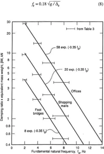
As shown in Figure 4 the results of Table 2 can be approxi-mated by the following criterion for walking vibrations:
セwRZZ@ K exp (-D.35f,) (4a) where f o is the fundamental natural frequency (Hz) and K is a constant given in Table 3 which depends on the acceleration limit for the occupancy. Equation 4a can be inverted to express the criterion for walking vibrations in terms of mini-mum fundamental natural frequency:
.t, 2:: 2.86ln
{セセ}@
(4b) The following section provides guidance for estimating the required floor properties for application of Equations 4.DAMPING ratioセ@
The damping ratio depends primarily on non-structural com-ponents and furnishings. The Canadian steel structures speci-fication (CSA, 1989) recommends damping ratios of0.03 for a bare floor; 0.06 for a finished floor with ceiling, ducts, flooring, and furniture; and 0.12 for a finished floor with partitions. Murray (1991) recommends damping ratios of 0.01 to 0.03 for a bare floor, 0.01 to 0.03 for ceilings, 0.01 to 0.10 for mechanical ducts, and 0.10 to 0.20 for partitions. These damping ratios, however, are based on vibration decay resulting from heel impact and include a component for
Table 2.
Minimum Value of セ@ W determined from Equation 3 for Satisfactory Performance
Floor Office Shopping
Frequency Floors Malls Footbridges
f0 (Hz) kN (kips) kN (kips) kN (kips)
1.6 to 2.2 28 (6.3) 9.3 (2.10) 4 (0.50) 3.2 to 4.4 14 (3.2) 4.7 (1.05) 2 (0.45) 4.8 to 6.6 7 (1.6) 2.3 ( 0.52) 1 (0.22} 6.4 to 8.8 3.5 (0.8) 1.1 (0.26) 0.5(0.11)
geometric dispersion of vibration as well as frictional and material damping. More recent testing of modal damping ratios shows that the frictional and material damping ratios are approximately half of the values determined from heel impact tests. Based on available information (Wyatt, 1989; ISO, 1992), Table 3 recommends damping values for use in the proposed criterion, Equation 4.
naturalfrequencセONLandequnalent@
MASS WEIGHT,
WIn the case of a simply supported panel such as a footbridge, the natural frequency is equal to the fundamental beam fre-quency of the panel and the equivalent mass weight is equal to the panel weight. Floors of steel construction, however, are two-way systems with many vibration modes having closely
QVセMMMMMMMMMMMMMMMMMMMMMMMMMMMMMMMMML@ a) SPAN 1: NATURAL FREQUENCY 2.05Hz •,.-CALC. BY EQN.(2l, R = 0.7 Ct 12 it
z
0 10セ@
セ@ /MEASURED w 8 0 セ@ :11:: < 6 w a.. 4 2 0 1.7 1.9 2.0 2.1 2.2 2.3 2.4 STEP FREQUENCY, Hzspaced frequencies. Natural frequency and equivalent mass weight of a critical mode in resonance with a harmonic of step frequency is therefore difficult to assess. A dynamic modal analysis of the floor structure can be used to determine the critical modal properties, but there are factors that are difficult to incorporate in the structural model. Composite action and discontinuity conditions are two such factors, but more diffi-cult to assess is the effect of partitions and other non-structural components. An unfinished floor with uniform bays can have a variety of modal pattern configurations extending over the whole floor area, but partitions and other non-structural com-ponents tend to constrain the modal configurations to local areas in such a way that the floor vibrates locally like a single two-way panel. The following simplified procedure is recom-mended to estimate the properties of such a panel. Some of the recommendations are based on judgment guided by floor test experience. Further research is needed to obtain better estimates, particularly for W.
The floor is assumed to consist of a concrete slab (or deck) supported on steel joists or beams (open-web or rolled sec-tions) which, in tum are supported on walls or on steel girders between columns. The fundamental natural frequency,..fo, and equivalent mass weight, W, for a critical mode is estimated by first considering a "joist panel" mode and a "girder panel" mode separately and then combining them. If the joist span is less than half the girder span, however, both the joist panel mode and the combined mode should be checked against the criterion, Equations 4.
b) SPAN 2: NATURAL FREQUENCY 4.17 Hz
a-CALC. BY EON.[2], R • 0.7
2.0 2.1 2.2 2.3 2.4
STEP FREQUENCY, Hz
In the following, the concrete modulus of elasticity is assumed equal to 1.35 times that assumed in current structural standards, the increase being due to the greater stiffness of concrete under dynamic, as compared to static, loading. Also for determining composite moment of inertia, the width of concrete slab is equal to the member spacing but not more than 0.4 times the member span. For edge members, it is half of this value plus the projection of the slab beyond the member center line.
Also the floor weight per unit area, w, should include the sustained component of live load (approximately 0.5 k.Pa
(1 I psf) for offices).
JOIST PANEL MODE
The joist panel mode is associated with the natural frequency of the joist or beam alone. The natural frequency of this mode can be estimated from the simple beam formula
fi=O.l8..fg!tlj (5)
where tlj is the deflection of a beam or joist relative to its supports due to the weight supported by the individual beam or joist. Composite action is normally assumed provided the joists are directly connected to the concrete slab by welds to steel deck. Normally the joists or beams are assumed to be simply supported unless dynamic restraint is verified by a dynamic analysis or experiment. For open-web joists, shear deformations should be included in the calculations for tlj.
The mass weight of the joist panel mode can be estimated from
(6)
where w is the floor weight per unit area, Lj the joist or beam span, 。ョ、セ@ the effective joist panel width determined from
(7)
where セ@ is the flexural rigidity per unit width in the joist direction and D, the flexural rigidity per unit width in the slab direction (including a correction for shear in open-web joists) based on the moment of inertia of the uncracked concrete (assume an average thickness tc for ribbed decks). The form of Equation 7 is based on orthotropic plate action and the factor 2 was determined by calibration to floor data as de-scribed later. The effective panel width, セᄋ@ determined by Equation 7 should be assumed . to have an upper limit of two-thirds of the total width of the floor perpendicular to the joists or beams.
Where the beams or joists are continuous over their sup-ports (including rolled sections shear connected to girder webs), and an adjacent span is 0.7Lj or greater, the effective joist panel weight, '"j, can be increased by 50 percent. The reason for this increase is that continuity over supports en-gages participation of adjacent floor panels in the fundamen-tal mode of vibration. (Wyatt (1988) recommends an increase
Table 3.
Values of K and セヲッイ@ use in Equation (4)
K
kN (kips) セ@
Offices, residences, churches 56 (13.0) 0.03*
Shopping Malls 20 (4.5) 0.02
Footbridges B (1.6) O.Q1 *0.05 for full-height partitions, 0.02 for floors with few non-structural com-ponents (ceilings, ducts, partitions, etc.) as can occur in churches
of 70 percent where the adjacent span is 0.8Lj or greater, 100 percent when it is l.OLj.)
GIRDER PANEL MODE
The girder panel mode is associated with the natural fre-quency of the girder alone. The natural frefre-quency of this mode can be estimated from
fs
= 0.18..Jg
I fl.8 (8) 58 exp. (-0.35 f 0) z""'
3:" 8 C!l. :E 0> 6 ·a; 3: 5 20 exp. (-0.35 f0) U> U>.,
4 E E.,
3 セ@ ·s g-)( 2 0 ᄋセ@ 0> c: ·c. E.,
0 0.6 0.4 0 2 4 6 8 10 12 14Fundamental natural frequency, 10, Hz
where セ X@ is the deflection of individual girders relative to their supports due to the weight supported. Composite action can be assumed when the girders are directly connected to the concrete slab, for example by welds to the steel deck. When the girders are separated from the concrete slab by beams or joist seats (shoes), they act as Vierendeel girders, i.e. partially composite. It is recommended that the moment of inertia of girders supporting joist seats be determined from:
I8 ::=: Inc
+
(Ic - Inc) I 2for seat heights 75 mm (3 in.) or less, and
I8 ==Inc+ (1,-InJ I 4
(9a)
(9b)
for seat heights 100 mm (4 in.) or more, where Inc and I, are
non-composite and fully composite moments of inertia re-spectively. (These recommendations are subject to change depending on the results of current research.) Normally the girders are assumed to be simply supported unless dynamic restraint is verified by analysis or experiment.
The mass weight of the girder panel mode can be estimated from
(10) where L8 is the girder span and B8 is the effective girder panel width determined from
(11) where D8 is the flexural rigidity per unit width in the girder direction 。ョ、セ@ the flexural rigidity per unit width in the joist direction. Equation 11 is the same as Equation 7 except that the factor 2 is reduced to 1.6 to take into account discontinuity of joist systems over supports; if the joists consist of rolled beams shear connected to girder webs the factor 1.6 can be increased to 1.8. B
8 determined by Equation 11 should be
assumed to have a lower limit equal to the tributary panel width supported by the girder and an upper limit of two-thirds of the total floor width perpendicular to the girders.
Where the girders are continuous over their supports, and an adjacent span is 0.7L8 or greater, the mass weight, セN」。ョ@
be increased by 50 percent. This is due to participation of adjacent floor panels, as discussed above for the joist panel mode.
COMBINED MODE
Combined flexibilities of the joists and girders reduces the natural frequency and makes the floor more susceptible to noticeable walking vibration. For design purposes this can be taken into account by a "combined" mode whose properties may be estimated using the following interaction equations:
(i) The fundamental natural frequency can be approxi-mated by the Dunkerly relationship:
(12)
(ii) The equivalent mass weight can be approximated by the interaction formula:
セェ@ セX@
W==--W+--W
セェ@
+
セァ@ I セェ@+
セX@ g(13) If the girder span, L8, is less than the joist panel width, セN@
the combined mode is restricted and the system is effectively stiffened. This can bt< accounted for by reducing the deflec-tion, セ XL@ used in Equations 12 and 13 to
(14) where
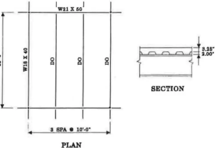
EXAMPLE
Determine if the framing system for the typical interior bay shown in Figure 5 satisfies the proposed criterion for walking vibration. The structural system supports the office floors without full-height partitions. For ease in reading, this exam-ple will be carried out using Imperial units.
Concrete: 110 pcf,fc' = 4,000 psi; n = E, I 1.35 E, = 9.3 Deck thickness= 3.25 in.+ 2 in. ribs= 5.25 in. Deck weight
=
42 psfBeam Mode Properties
With an effective concrete slab width of 120 in. < 0.4 Lj = 0.4
x
35x
12 = 168 in., and considering only the concrete above the steel form deck, the transformed moment of inertia セ@ = 2,105 in.4 For each beamwj = 10(11 + 42 + 4 + 40 I 10) = 610 plf
which includes 11 psflive load and 4 psffor mechanical/ceil-ing, and
_ 5wfj _
5 x 610x 354x 1,728
セM
384£Ij-384 X 29 X 106 X 2,105 0.337 in. The beam mode natural frequency from Equation 5 is:_[386
Jj
== 0.18\.j
0337
== 6.09 HzUsing an average concrete thickness, 4.25 in., the transformed moment of inertia per unit width in the slab direction is
D, = 12 X 4.253 I 12
X 9.3 = 8.25 in.41ft
The transformed moment of inertia per unit width in the beam direction is (beam spacing is 10 ft)
セ@ = 2,105 I 10
=
210.5 in.4/ftセ]@ 2(8.25 QRQPNUIGセ T HSUI@ = 31.3 ft
Since this is a typical interior bay, the actual floor width is at least 3 x 30 = 90 ft, and
%
x 90 = 60 ft > 31.3 ft. Therefore, the effective beam panel width is 31.3 ft.The mass weight of the beam panel is from Equation 6, adjusted by a factor of 1.5 to account for continuity:
ltj = 1.5(610110)(31.3 X 35) = 100,238 lbs = 100 kips
Girder Mode Properties
With an effective slab width of 0.4 X 30 X 12 = 144 in. and considering the concrete in the form of deck ribs, the trans-formed moment of inertia /8 = 3,279 in.4 For each girder
Wg = 2.5 (610 X 35) I 30 +50= 1,829 plf,
セ@
=
5 X 1,829 X 304 X 1,728=
0. 3SQ in. 8 384 X 29 X 106 X 3,279 and_{386
/g = 0.18-\j
0.350
= 5.98 Hz With セ@ = 210.5 in.41ft and D8
=
3,279 I 35=
93.7 in. 41ft, Equation 11 givesB8= 1.8 (210.5 I YSNWIGセ@ (30) = 66.1 ft
which is less than 2/ 3 (3 x 35) = 70 ft. From Equation 10
セ@
=
(1829 I 35)(66. 1 X 30)=
103,626 lb=
104 kipCombined Mode Properties
In this case the girder span (30 ft) is less than the beam panel width (31.3 ft) and the girder deflection, 118, is therefore reduced according to 0.350 x 30 I 31.3 = 0.334 in. From Equation 12, 0
•
セ@ 0 0 0...
1:1 1:1 1:1...
セ@ej
セ
YNRUB@
2.00'.;
SECTIONI
a SPA • 1o·.o· II
PLANFig. 5 Floor framing system-typical interior bay.
fo=
0.18 -1386 I (0.337+
0.334) = 4.32 Hz and from Equation 130.337 0 334
W
=.
0.337 + 0.334 (lOO)+ 0.337. + 0.334 (104)= 102 kips For office occupancy without full-height partitions, セ@=
0.03 from Table 3, thusセw@ = 0.03
x
102 = 3.06 kips EvaluationApplication of Equations 4 for offices (see Table 3) results in
セw@ = 3.06 kips> 13 exp ( -0.35
x
4.32) = 2.87 kips orfo
= 4.32 Hz;::: 2.86 In (13 I 3.06) = 4.14 HzThe floor is therefore judged satisfactory.
EDGE PANEL MODE
Unsupported edges of floors can cause a special problem because of low-mass weight and sometimes decreased damp-ing. Normally this is not a problem for exterior floor edges, because of stiffening by exterior cladding or because walk-ways are not located near exterior walls. Problems have occurred, however, at interior floor edges adjacent to atria. These edge members should often be made stiffer than current practice suggests by use of the following assumptions in the proposal criterion.
Where an interior edge is supported by a joist, the equiva-lent mass weight of the joist panel can be estimated using Equation 6 by replacing the coefficient 2 with 1 in Equation 7. Where an interior edge is supported by a girder, the equi va-lent mass weight of the girder panel should be estimated on the basis of the tributary weight supported by the girder. These edge panels are then combined with their orthogonal panels as recommended above.
CALmRATION OF PROPOSED CRITERION TO EXPERIENCE
The factor 2 in Equation (7) was determined by calibration to data on one-way joist floor systems in Table 1 of Allen and Rainer (1976). The results of applying the proposed criterion, including recommended design parameters, to floors that have been evaluated and tested is given in Tables 4 and 5. Table 4 confirms application of the proposed criterion for one-way systems, two-way systems, and interior edge panels. Application of the CSA criterion (CSA, 1989) to the two-way floor systems in Table 4, on the other hand, predicts that all are satisfactory when in fact floors 12 and 13 are definitely unsatisfactory. Table 5 confirms application of the proposed
criterion to two-way systems except for floor 3, a heavy floor (3.6 kPa) with continuity in both directions. Two factors for
Table 4.
Application of Proposed Design Criterion to Tested Floors
Panel セwHォnI@
Measured Width B(m) Damping
Frequency Equation 7 r。エゥッLセ@ Criterion User
Case Reference or Location f0 (Hz) Span L(m) & 11 Table3 Calc. Equation 4a Rating2
One-Way Joist Systems
1 Allen and Rainer (1976), #13 4.0 22.2 9.7 0.03 19.3 14.3
s
2 #9 4.5 21 .6 11.9 0.03 26.9 12.0
s
3 #24 4.6 16.5 11 .2 0.03 16.6 11.6s
4 #5 5.3 18.3 8.8 0.015 6.0 9.1u
5 #10 5.3 18.6 7.8 0.015 5.4 9.1u
6 #2 5.5 14.6 8.6 0.03 9.4 8.5s
7 #1 6.0 10.7 8.3 0.03 6.6 7.1u
8 #18 6.0 17.1 9.8 0.015 7.5 7.1 8 9 #22 8.0 10.7 7.1 0.03 5.5 3.5s
10 #19 8.5 8.9 8.2 0.015 3.3 3.0 8 11 #17 8.8 8.7 7.6 0.015 2.5 2.7u
Two-Way Joist-Girder Systems
12 Quebec City 4.5 (7.6, 7.6)3 (9.1' 11 .9)3 0.03 6.2 12.0 Very U 13 Quebec City 5.4 (7.6, 7.6) (9.1' 8.6) 0.03 5.4 8.8
u
14 Quebec City 7.2 (7.6, 7.6) (7.4, 10.7) 0.03 5.2 4.7s
15 Matthews, et al (1982) 6.2 (9, 12.5) (9.7, 11.3) 0.03 9.5 6.6s
16 Pernica and Allen (1982) 5.2 (7.6, 12.2) (8.1, 15.0) 0.02 11.8 3.2s
Interior Edge Panels
I
17 Quebec City 5.1 13.7 2.3 0.03 2.4 9.7 Very UI
18 Edmonton 5.1 17.5 4.6 0.03 8.4 9.7u
19 Pernica and Allen (1982) 5.6 12.2 3.3 0.02 2.5 2.8
u
r
Notes:I
1
K =58 for all cases except #16 and #19, where K = 20 applies
'
:3-rhe first entry inside the brackets refers to the joist panel, the second refers to the girder panel 2U =unsatisfactory, S =satisfactory, B = borderlineunsatisfactory perfonnance of this floor are low damping
セ」イゥエ・イゥッョ@ just met ヲッイセ]@ 0.015) and vibration transmission due to girder continuity. Floors 7 and 10 are predicted to be marginal.
The proposed criterion can also be compared to existing .:riteria. Table 6 makes this comparison on the basis of mini-mum values of セBj@ for one-way beam or joist systems. The basis for the values shown in Table 6 is given in Appendix III. For office floors, Table 6 shows that all criteria are similar for resonance with the third hannonic of the step frequency (5 to .., Hz). This is not surprising because existing design criteria ;.rre based to a large extent on experience with floors in the frequency range 5 to 8 Hz.
The criteria, however, differ at other floor frequencies. The CSA criterion is insufficient for frequencies less than 5 Hz md conservative for frequencies beyond 7 Hz. The Murray .:riterion has tendencies similar to the CSA criterion, but the Jiscrepancy with the proposed criterion is less severe. The Wyatt criterion is close to the proposed criterion within a
broad frequency range, 3 to 8 Hz, but is more conservative beyond 8Hz.
For footbridges the proposed criterion is apparently a little more conservative than the OHBDC (1983) criterion, but this is offset by the difference in recommended values ッヲセ@ (0.01 vs. 0.005 to 0.008 in the OHBDC). Third and fourth harmonic resonance is not adequately considered by the OHBDC but this is not serious in practice because footbridges with these frequencies generally have sufficient mass to satisfy the pro-posed criterion, Equation 4a.
Information on shopping centers is scarce. Application of · Equation 4a for shopping centers to the floor data in Cases 16 and 19 of Table 4, however, indicates agreement with user reaction.
Tables 4-6, as well as Figure 3, therefore confirm the applicability of the proposed criterion for walking vibration to a wide variety of structures and occupancies.
Table 5.
Application of Proposed Design Criterion til Floors Investigated by Murray (1981)1 Span (m) Panel Width B(m)
Estimated セwHォnI@
Calculated Damping Criterion
Frequency f0 Joist or r。エゥッLセ@ Equation User
Case (Hz) Beam Girder Beam Girder Table 3 Calculated (4a) Rating
1 7.0 10.5 6.0 6.3 11.1 0.015 2.0 4.9
u
2 7.0 10.5 6.0 6.3 11.1 0.05 6.6 4.9s
3 4.0 7.3 12.2 9.22 16.92 0.02 18.6 14.1u
4 7.7 7.0 7.2 7.2 9.0 0.015 2.0 3.9u
53 5.9 12.2 Wall 7.3 ? 0.015 3.5 7.3u
6 5.9 12.2 Wall 7.3 ? 0.05 11 .7 9.2s
7 5.3 13.4 6.4 8.0 19.8 0.03 9.3 9.2u
8 6.1 9.1 6.1 6.4 11.6 0.03 3.9 6.9u
9 5.1 5.5 12.5 6.5 9.1 0.03 6.7 9.6u
10 5.2 11 .6 9.8 8.72 19.9 0.02 9.7 9.4u
11 3 6.4 12.2 ? 7.9 ? 0.02 5.1 6.1u
Notes:1 All open web joist on girder systems except #3 and #1 0 (beams shear connected to girders) 2M embers continuous over supports ( Wj or Wg increased by 1.5)
3 Joist systems supported on stiff girders, frequency 10 estimated from セ@
NATURAL FREQUENCIES GREATER THAN 9HZ When the natural frequency is greater than 9 Hz, harmonic resonance does not occur, but walking vibration can still be a problem. Because the natural frequencies are high compared to the main loading frequencies, the floor response is gov-erned primarily by stiffness relative to a concentrated load. Experience indicates a minimum stiffness of approximately 1 kN per mm (5.7 kips per in.) deflection for office and residential occupancies.
For light floors with natural frequencies in the range 9 to 18 Hz there may also be adverse reaction to floor motion caused by step-impulse forces. Experience indicates that ad-verse reaction to step impulses depends primarily on mass (i nitial .fl.oor velocity equals impulse div ided by mass) and vibration decay ti me, the shorter the decay time the better. The decay time decreases in proportion to clamping ratio limes fl oor frequency. Wyatt (1 989) recommend an impul se criterion beyond 7 Hz floor frequency, but beyond approxi-mately 9 Hz the criterion becomes overly conservative be-cause il ignores the benefits of decreased decay lime. Ohlsson ( 1988) reconunends an impulse criterion which takes decay time into account, but the criterion is complex for design. The resonance criterion, Equation 4a, is in a form that correctly
reflects impulse discomfort except that the right-hand side has not been correctly determined. If, however, Equation 4a with
K = 58 for office floors is extended beyond 9Hz, it decreases rapidly until approximately 18Hz when the stiffness criterion of 1 kN/mm (5.7 k/in.) starts to control the design of the floor. Application of Equation 4a to the examples in Ohlsson (1988) also indicates that it gives a reasonable evaluation for floors between 9 and 18 Hz.
To ensure satisfactory performance of office and residen-tial floors with frequencies greater than 9 Hz it is recom-mended that Equations 4 be used in conjunction with the stiffness criterion of 1 kN/mm (5.7 k/in.).
CONCLUSION
Walking forces produce motions which are related to reso-nance, impulse response, and static stiffness . Resonance con-trols the design of floors and footbridge with natural frequen-cies less than approximately 9Hz, tatic stiffness controls the design of floors with frequencies greater than approxi mately I 8Hz, and impulse respon ecomrols the design of floors with frequencies in between.
A simple criterion for re onance vibration of floor and footbridge structures, Equations 4, is proposed for design, along with a recommended procedure for determining the
Table 6.
Comparison of Various Design Criteria for Walking Vibrations
Minimum Value of Damping Ratio Times Effective Mass Weight, セw Q HォnI@
Natural
Frequency Offices, Residences Footbridges
f0 (Hz) Equation 4a CSA (1989)1 Murray (1981)1 Wyatt (1989) Equation 4a OHBDC (1983)
2 28.8 NA NA NA 4.0 3 4 14.3 4 5.8-7.6 17.5 2.0 1.8 6 7.1 6 5.8-7.6 8.8 1.0
-8 3.5 7 5.8-7.6 3.01 0.5 -10 1.75 8 5.8-7.6 3.01 0.24 -Note:1 Results are given for a standard case of finished floor without full-height partitions Hセ@ = 0.03)
required floor properties. The proposed criterion, based on acceptable vibration for human reaction, compares well with existing criteria and is confirmed by experience with tested floors. Recommended values of the criterion parameters, however, are expected to be improved by further experience and research.
Floors of offices and residential occupancies with frequen-cies greater than 9 Hz should also be checked both for a minimum static stress under concentrated load of 1 kN/mm (5.7 kips/in.) and for impulse response by means of Equa-tions 4.
APPENDIXI:REFERENCES
1. American Institute of Steel Construction, Specification
for Structural Steel Buildings-Allowable Stress Design and Plastic Design, AISC, Chicago, 1989.
2. Allen, D. E. and Rainer, J. H., "Vibration Criteria for Long-Span Floors," Canadian Journal of Civil
Engineer-ing, 3(2), June, 1976, pp. 165-171.
3. Bachmann H., "Case Studies of Structures with Man-Induced Vibrations," Journal of Structural
Engi-neering, ASCE, Vol. 118, No.3, 1992, 631-M7. 4. British Standard BS5400, Part 2: Steel, Concrete and
Composite Bridges: Specification for Loads, Appendix C,
British Standards Institution, 1978.
5. Canadian Standard CAN3-SJ6. l-M89: Steel Structures
for Buildings-Limit States Design, Appendix G: Guide for Floor Vibrations, Canadian Standards Association, Rexdale, Ontario, 1989.
6. International Standard ISO 2631-2, Evaluation of Human
Exposure to Whole-Body Vibration-Part 2: Human Ex-posure to Continuous and Shock-Induced Vibrations in Buildings ( 1 to 80Hz), International Standards Organiza-tion, 1989.
7. International Standards ISO 10137, Basis for the Design
of Structures-Serviceability of Buildings Against Vibra-tion, International Standards Organization, 1992.
8. Lenzen, K. H., "Vibration of Steel Joists," Engineering
Journal3(3), 1966, pp. 133-136.
9. Matthews, C. M., Montgomery, C. J., and Murray, D. W., "Designing Floor Systems for Dynamic Response,"
Structural Engineering Report No. 106, Department of Civil Engineering, University of Alberta, Edmonton, Al-berta, 1982.
10. Murray, T. M., "Acceptability Criterion for Occupant-In-duced Floor Vibrations," Engineering Journal, 18(2), 1981, 62-70.
11. Murray, T. M., "Building Floor Vibrations," Engineering
Journal, Third Quarter, 1991, 102-109.
12. Ontario Highway Bridge Design Code, Ontario Ministry of Transportation and Communication, Toronto, 1983. 13. Ohlsson, S. V., "Ten Years of Floor Vibration
Research-A Review of Research-Aspects and Some Results," Proceedings of
the Symposium/Workshop on Serviceability of Buildings. Vol. 1, Ottawa, 1988, pp. 435-450.
14. Pemica, G., and Allen, D. E., "Floor Vibration Measure-ments in a Shopping Centre," Canadian Journal of Civil
Engineering, 9(2), 1982, pp. 149-155.
15. Rainer, J. H., Pernica, G., and Allen, D. E., "Dynamic Loading and Response of Footbridges," Canadian
Jour-nal of Civil Engineering, 15(1), 1988, pp. 66-71. 16. Tredgold, T., Elementary Principles of Carpentry, 2nd
Ed., Publisher unknown, 1828.
17. Wyatt, T. A., "Design Guide on the Vibration of Floors,"
Steel Construction Institute Publication 076, London, 1989.
APPENDIX II: NOTATION The following symbols are used in this paper: a = acceleration
ao = acceleration limit
B = effective width of a panel
D = flexural rigidity or transformed moment of inertia per unit width of a panel
g j K L p R
w
w= modulus of elasticity for steel = step frequency
= natural frequency of joist or beam panel = natural frequency of girder panel
= fundamental natural frequency of floor structure = acceleration due to gravity; subscript indicating
girder
= ith harmonic of step frequency = subscript indicating joint or beam
=
factor in Equation 4 taking into account occupant sensitivity to vibration= span of joint, beam, or girder (with subscript j or g)
=weight of a person (0.7 kN assumed)
=
reduction factor in Equation 2=
effective mass weight of floor vibrating in the fundamental mode= unit weight of floor panel, including acting live load
wj or w8
=
unit weight of joist or girder per unit lengthai = dynamic load factor for ith harmonic of step fre-quency
p
=
damping ratioセ@ = deflection of member under weight supported
APPENDIX III: BASIS FOR COMPARISON OF VIBRATION CRITERIA
Existing design criteria for walking vibration can be com-pared with the proposed criterion by considering a standard joist or beam panel on stiff supports . To make a valid com-parison, each criterion must be considered as a total package. This requires adjustments to the criteria to take account of differences in the form of the design equations and in the recommended values of design parameters . To make a com-parison, all criteria will be transformed to a common measure
Pl-1-J
as defined for the proposed criterion.The following frequency relationship for a simply sup-ported joist panel will be used to transform all criteria to the common measure, P l-1-):
t = 1!:.-
/gif
0 2B|O セ@
where w is the unit weight of the panel
Canadian Standards Association (CSA, 1989)
(A1)
This criterion has been used in Canada since 1975, with minor modifications in 1984. For the standard joist panel, the CSA criterion can be expressed as follows:
w(40tJLj (kN) > 0.61, I (a0 I g) (A2)
where ( . is the effective concrete thickness, 40tc is the effec-tive slab width, and an I g is a limiting heel-impact
accelera-tion determined from Figure 6. Equaaccelera-tion A2 can be expressed in terms of l-1-j if a correction is made for the effective panel width. For a typical case of a 5.5 Hz floor, span Lj = 12m and concrete thickness tc = 75 mm, application of Equation 7
results in an effective width of 8.3 m or 110tc compared to
40tc in Equation A2. If Equation A2 is multiplied by 11
op
140 it becomes(A3) Minimum values of セャMQMェ@ for the CSA criterion in Table 6 were determined from Equation A3 using the criterion for finished floors in Figure 6 。ョ、セ]@ 0.03 from Table 3.
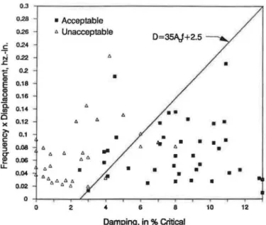
Murray (1981)
On the basis of a review of field data from 91 floors, Murray (1981) recommended the following criterion, presently widely used in the U.S.:
セ@ > 0.35Ao..fo
+
0.025 (A4)where Ao is the initial amplitude of vibration (inches) due to
"'
J'. Q..
c g iii Q; Q; u u..
.><..
Q) 0.. 100 so 20"
---10 s_______
Walkmg v1bra11on __, (finished floors) 2 ⦅キセォセァNAセセセョM _ (bare floors) 1 0 Continuous v1brat1on OS ( 10 to 30 cycles) 0. 1 Frequency , Hz セ@ / / / // Cntena for wa lkmg v1brat10ns : acceleration determined by heel 1mpact test
a,
I"/\
c " V ... Cntenon for contmuous VIbration average peak a..-'T -n·---
.. 0-fl· -
/vvvv
Fig. 6. Annoyance criteria for floor vibrations in residential, school, and office occupancies (CSA. 1989).
a standard heel impact. Equation A4 is plotted in Figure 7 along with the floor data. To determine Ao Murray provides the following expression for a simply supported one-way floor system:
(AS) where Lls is the static deflection of the joist panel under a concentrated load of 600 lb. and DLF is a dynamic load factor to obtain the maximum amplitude of vibration for a standard heel impact. DLF ranges from 0.15.fo atfo =4Hz to 0.12fo at
fo
= 10Hz, and can therefore be approximated by 0.14fo, itsvalue atfo =6Hz. Thus,
_ (1.14fo) 600LJ
Ao-
TXセbm@
(A6)where
/3.
11 is the effective joist panel width as defined later.Substitution of Equation A6 in Equation A4 after elimination of セ@ by means of Equation Al results in the following criterion:
584
セ@
>
キセlェ@+
0.025 (A7) For the standard case of finished office floor withoutfull-ィ・ゥァィエー。イエゥエゥッョウLセ@ = 0.03 according to Table 3 。ョ、セ]@ 0.045 according to Murray. For this case Equation A 7 becomes
wBMLj == 584 I (0.045 - 0.025) == 29,200 (A8) Murray ( 1991) provides expressions for determining BM in terms of beam or joist spacing times the number of effective joists. Two expressions are used, one for normal hot-rolled beam (spacing more than 30 in.); the other for closely spaced
0.3 0.28 0.26
c
0.24....
N 0.22 .cc:-
0.2 CD E 0.18 CD 0 0.16 ca a. 0.14 CD i5 0.12 )( >o 0.1 0 c CD 0.08 ::J 0' !!! 0.06 u. 0.04 0.02 0 0 • Acceptable " Unacceptable"
•
"
"
"
"
•
" " "
"
""
..
•
""
•
66. lJ. A fl. セ@"
""
2 4"
•
•
6 D=35AJ+2.5••
•
•
..
0.•
•
•
•
•
•
8•
•
• •
•
• •
•
•
•
•
•
•
•
•
10 12 Damping, in % CriticalFig. 7. Murray criterion, Equation (A4), compared to floor data (Murray 1981).
joists (30 in. or less). The expression for narrow spacing is equivalent to
(A9) where セ@ is defined according to Equation 7, and the expres-sion for wide spacing can be approximated by
v.
bュ]ャNPS{セ}@
lェ]PNUQUセ@
(AlO)Substitution of Equations A9 or AlOin Equation A8 results in minimum values of
Hj
equal to 43,260 lb for narrow spacing and 56,700 lb for wide spacing. For the standard case, セ@ == 0.03, the corresponding minimum values of セhェ@ included in Table 6 are 1,300 lb (5.8 kN) and 1,700 lb (7.6 kN).Wyatt (1989)
Wyatt (1989) proposed two design criteria for office floors, one a resonance criterion for floor frequencies up to 7 Hz, the other an impulse response criterion for floor frequencies greater than 7 Hz. For the one-way beam or joist system, the resonance criterion can be expressed (with rearrangement and change of symbols) as
(All)
where C1 is a loading coefficient (0.4 for second harmonic loading and 0.2 for third harmonic loading), F is a rating factor which depends on the office environment ( 12 for a busy office, 8 for a general office, and 4 for a special office) and
Bw is the joist panel width. For the one-way system Wyatt
recommends
[
gDs]v.
Bw=4.5
J!w
(A12)which can be expressed in the same form as Equation 7 by use of EquationAl. After substitution, Bw in Equation A12 become equal to QNXセ L@ where セ@ is defined by Equation 7 . Wyatt , however, recommend a concrete modulus elasticity 25 percent higher than recommended forD, in Equation 7. With this correction B,., becomes equal to QNYセN@ Equation All can therefore be expressed as
(A13) for floor frequencies below 7 Hz. Table 6 contains minimum values of セhェ@ assuming F == 8 for a general office .
For floor frequencies greater than 7 Hz Wyatt recommends the following impulse criterion:
wSLj> 294/ F (A14)
where Sis the member spacing. Equation Al4 may be ex-pressed in terms ッヲセ@
Hj
if it is multiplied by セセ@IS.
Based onan assumed beam spacing of 2.5 mused in Wyatt's examples and a typical value セ@
=
6.8 m for an 8 Hz floor of span 9 m and concrete thickness of 75 mm. Equation Al4 can be approximated byーセ@ >
soop;F
(Al5)Table 6 contains a minimum value of Equation Al5 at
fo = 8 Hz for a general office floor for which F = 8 and
p
= 0.03.Footbridges-Ontario Highway Bridge Design Code (OHBDC, 1983)
The OHBDC (1983) design criterion for footbridges is based on a pedestrian or jogger exerting a dynamic force of
aP cos 2rtft where P is 0.7 kN,
a.
= 0.257 and f, the stepfrequency, takes on any value between 1 and 4 Hz. The footbridge is modeled as an SDOF beam which vibrates at the
first flexural frequency,fo. For a simply supported footbridge, the resonance response for flexural frequencies up to 4 Hz can be determined from Equation 2 with a value of R which is determined by the length of the footbridge. If, for a typical case R is assumed equal to 0.7, the maximum acceleration is determined from
amax/ g
=
0.7(0.257)0.7IPlij
=
0.126 Plij (Al7) where セ@ is the weight of the footbridge. The OHBDC rec-ommends limiting values of amax I g equal to 0.042 atfo=
2Hz and 0.072 atfo = 4Hz. Thus Equation A17 can be inverted to a criterion for minimum value of pセ@ equal to 0.126 I 0.042= 3 kN atfo =2Hz and 0.126 I 0.072 = 1.8 kN atfo =4Hz.
For a flexural frequency beyond 4 Hz, the OHBDC gives an incorrect assessment because it neglects resonance with the higher harmonics of the walking and jogging forces.