https://doi.org/10.4224/20377938
READ THESE TERMS AND CONDITIONS CAREFULLY BEFORE USING THIS WEBSITE.
https://nrc-publications.canada.ca/eng/copyright
NRC Publications Archive
Archives des publications du CNRC
For the publisher’s version, please access the DOI link below./ Pour consulter la version de l’éditeur, utilisez le lien DOI ci-dessous.
Access and use of this website and the material on it are subject to the Terms and Conditions set forth at Modelling of the Proteo Model D/94
McLellan, A.
https://publications-cnrc.canada.ca/fra/droits
L’accès à ce site Web et l’utilisation de son contenu sont assujettis aux conditions présentées dans le site
LISEZ CES CONDITIONS ATTENTIVEMENT AVANT D’UTILISER CE SITE WEB.
NRC Publications Record / Notice d'Archives des publications de CNRC:
https://nrc-publications.canada.ca/eng/view/object/?id=b85905e2-c56d-4a00-8329-5ceb6325133a https://publications-cnrc.canada.ca/fra/voir/objet/?id=b85905e2-c56d-4a00-8329-5ceb6325133a
Author(s)
Modelling of the Proteo Model D/94
Andrew McLellan
IMTI-TR-015 (2003/02) Classification: None/aucune
February 2003 / Février 2003 Distribution: Unlimited/illimité
Integrated
Manufacturing
Technologies
Institute
Institut des
technologies de
fabrication
intégrée
Publication
INTEGRATED MANUFACTURING INSTITUT DES TECHNOLOGIES TECHNOLOGIES INSTITUTE DE FABRICATION INTÉGRÉE
Pages: iii, 35p
REPORT
Date: February / Février 2003RAPPORT
Fig. SAP Project #
Diag. 13 # de Projet de SAP 55-TR101-1-T
For Unlimited
Pour illimité None / aucune
(Classification)
Submitted by
Présenté par Sherman Lang
Group Leader
First Author
Auteur Premier Andrew McLellan Approved
IMTI-TR-015 (2003/02)
i TABLE OF CONTENTS List of Tables ……… ii List of Figures ……… ii Preface ……… iii 1.0 Acknowledgements ……… 1 2.0 Introduction ……… 2 3.0 Project Requirements ……… 2 4.0 Description ……… 3
4.1 Measurement of the Machine Parts ……… 5
4.2 Creation of the Drawings of the Measured Parts ……… 6
4.3 Creation of the Measured Parts in AutoCAD ……… 7
4.3.1 Example on How to Create the V-axis ……… 7
4.3.2 List of the AutoCAD Commands to Create Other Measured Parts ……… 11
4.4 Creation of the Proteo Model D/94 in AutoCAD ...……….. 12
5.0 Results ……… 14 5.1 Screen Shots ………... 14 6.0 Recommendations ……… 26 7.0 Conclusion ……… 26 8.0 Reference ……… 26 Appendix A Drawings ……… 27 A.1 W-axis ……… 28 A.2 V-axis ……… 29 A.3 Y-axis ……… 30 A.4 X-axis ……… 31 A.5 Z-axis ……… 32 A.6 Shell ……… 33
A.7 Shell (Part A) ………... 34
LIST OF TABLES
Table Page
1 Positive and Negative Ranges of the Axes from the Home Position …… 3
2 Required Views of the Drawings to Show all the Features of the Measured Parts ……… 6
3 List of the AutoCAD Commands to Create Other Measured Parts ……… 11
4 Axes Positions from Shell’s Reference Describing Machine’s Home Position ……… 13
LIST OF FIGURES Figure Page 1 Front View of Proteo Model D/94 ……… 3
2 Right Hand Rule ……… 4
3 W-axis ……… 15
4 V-axis ……… 16
5 Y-axis ……… 17
6 X-axis ……… 18
7 Z-axis ……… 19
8 Shell & Shell (Part A) ……… 20
9 Shell (Part B) ……… 21
10 W,V,Y,X and Z axes ……… 22
11 Proteo Model D/94, AutoCAD ……… 23
12 Proteo Model D/94, 3DStudio, Full View ……… 24
iii
PREFACE
Modelling of the Proteo Model D/94
This A.B. Lucas Secondary School Co-op Placement project was done by Andrew McLellan at the National Research Council (NRC) between the months of March and June in 2002.
The AutoCAD drawings were prepared with AutoCAD Release 14.01 and the first report was written with Microsoft Word 97 SR-1. The second report was written with Microsoft Word 2000 SR-1 for publication standards.
If there is any problem, contact Andrew McLellan:
Email: and_rew_16@hotmail.com
Phone: (519) 672-4374
Supervisor’s Comment
In this project, the dimensions of the parts were measured to the precision of the measurement tools can obtain with the naked eye. While some of the measured parts were manufactured precisely, some were not; decision was made to model the uneven parts approximately by taking either the average or the maximum values. For example, the maximum values will be used when the outer dimension has to be determined. In the future, when parts are manufactured precisely with a tighter tolerance, the model has to be exact for the simulation to reflect the real result.
1.0 Acknowledgements
The author would like to thank the people at NRC for their help and friendliness. Thanks to Steve Kruithof of the Virtual Environment Technologies Centre for converting the AutoCAD model into a 3DStudio model, the model looks great. Thank you Marcel Verner, Adam Rehorn, Dave Kingston and Stan Kowala for answering numerous technical questions. Thank you Brian Wong for supervising the project, without your help this project would have never been completed. Thank you Sherman Lang, Gian Vascotto and Georges Salloum from Management for allowing me to have this
2
2.0 Introduction
The Proteo Model D/94 is a milling machine made in Italy. It is used for cutting small complex parts. This machine is capable of 0.001 mm accuracy. The Model D/94 is a five-axis machine. It has W, V, Y, X and Z-axes. The W-axis is a table that holds the object being milled. The V-axis is used for tilting the W-axis. The Y-axis is used for vertical movement. The X-axis is used for horizontal movement. The Z-axis is for moving the spindle.
Some of the companies who make use of this machine are Grumman Aerospace, General Motors, Ford, General Electric and the U.S. Navy. For additional information about Model D/94, contact:
Barer Engineering Co. 1365 Basin Street
Montreal, Canada
H3C 1W3
Tel: (514) 937-3911
E-mail: info@barer.com
The purpose of this project is to provide the National Research Council of Canada with an AutoCAD file of the Proteo Model D/94 for virtual reality and simulation of this machine.
3.0 Project Requirements
1. Measurement Tools
a) 15cm Stainless-Steel Rule
b) 3.5m/12' Stanley Powerlock Tape
c) Electronic Digital Caliper
2. Computer Equipment
a) Hardware
i) Computer
x86 Family 6 Model 1 Stepping 9
AT/AT Compatible
163 252 KB RAM ii) 20' Monitor b) Software
i) Microsoft Windows NT System 4.00.1381
(Default Right-Handed Mouse)
4.0 Description
Figure 1. Front View of Proteo Model D/94 (Courtesy of Adam Rehorn)
The operator’s position is in front of the machine about two feet away from the shell as shown in Figure 1. On the left are the control panel and the Z-axis. On the right is the stack of the W, V, Y and X-axes. This stack is enclosed by the model defined as the “Shell (Part B)” [A.8]. The Shell (Part B) can be removed for the measurement of the axes.
Figure 1 also shows that the machine is very close to its home position (0,0,0). The home position is where all the axes are at the zero location. Table 1 shows the positive and negative ranges of the axes from the home position.
Table 1. Positive and Negative Ranges of the Axes from the Home Position Axis Positive
Range Negative Range Reference
W
(Rotational) No Limit (CCW) No Limit (CW) Looking from the top V
(Rotational) (CCW) 100 (CW) 10 Looking from the front
Y
(Directional) (Bottom) 43 (Top) 130 Using Right Hand Rule X
(Directional) (Back) 30 (Front) 174 Using Right Hand Rule
4
Figure 2. Right Hand Rule (Courtesy of Brian Wong)
Figure 2 defines the right hand rule. It is used as a guide to draw the AutoCAD model and is used as a reference for the movements of the physical axes.
The following procedure deals with how to produce an AutoCAD model of the Proteo D/94.
4.1 Measurement of the Machine Parts
A measurement tool is selected and the dimensions of each axis are measured. The Shell (Part B) is removed for the parts measurement.
W-axis
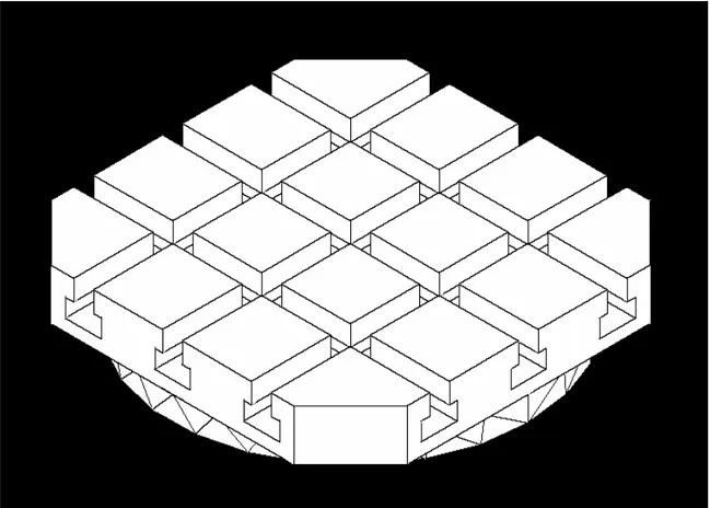
The electronic digital caliper is the best tool for this measurement because of all the small fine details in this axis. The W-axis sits on top of the V-axis. This table can rotate in either the CCW or the CW direction continuously. The purpose of this axis is to hold the material that is being cut by the Z-axis spindle.
V-axis
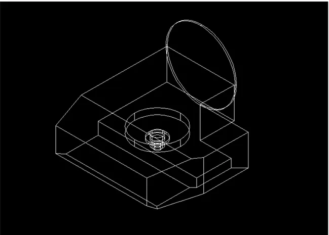
The V-axis is attached perpendicular to the Y-axis. In reference to the home position, the V-axis can rotate 100 degrees CCW and 10 degrees CW looking from the front of the machine.
Y-axis
This axis can only move vertically. It is mounted on the X-axis track.
X-axis
The X-axis moves on a track that is mounted on the right basin of the Shell (Part A). This axis moves forward and backward.
Z-axis
To measure most of this axis, the left side door cover, which is screwed in, should be opened for easy access. This axis moves on a track that is mounted on a very shallow basin of the Shell (Part A) located on the left. The Z-axis can move left or right on its track. Enclosed in the axis is the spindle motor. The Z-axis’s purpose is to hold the tool cutter.
Shell
The Shell’s purpose is to enclose all the axes, wires and pipes. This Shell [A.6] is modelled in two parts, the Shell (Part A) and the Shell (Part B). The Shell (Part A) is consists of the basin for the X-axis and the stand support for the Z-axis [A.7]. The Shell (Part B) is for the operator’s protection. It encloses the W, V, Y and X-axes.
6
4.2 Creation of the Drawings of the Measured Parts
In order to create the measured parts, the reference positions of each part are usually defined as the centre points. The centre point is easy to see, rigid, be noticeable on the axis, and should be at the middle of the axis. For example, the centre point of the V-axis is at the centre of the cylinder that rotates the V-axis (R72 in [A.2]). Sometimes there are exceptions that the reference positions are not at the centre.
The shell and the axes are drawn to scale on papers. All the drawings should be in proper drafting format and have all the information in order to make a good copy in AutoCAD.
In general, the drawings should have views of the front, the top and either the right or the left side. If these views cannot provide all the information for each feature, another view should be drawn. These views should show all the information to make an
AutoCAD file. The X-axis and the Z-axis drawings are drawn from the rear to avoid confusion with the hidden lines. The Y-axis has a cross-section because all the necessary information cannot be provided with the regular views.
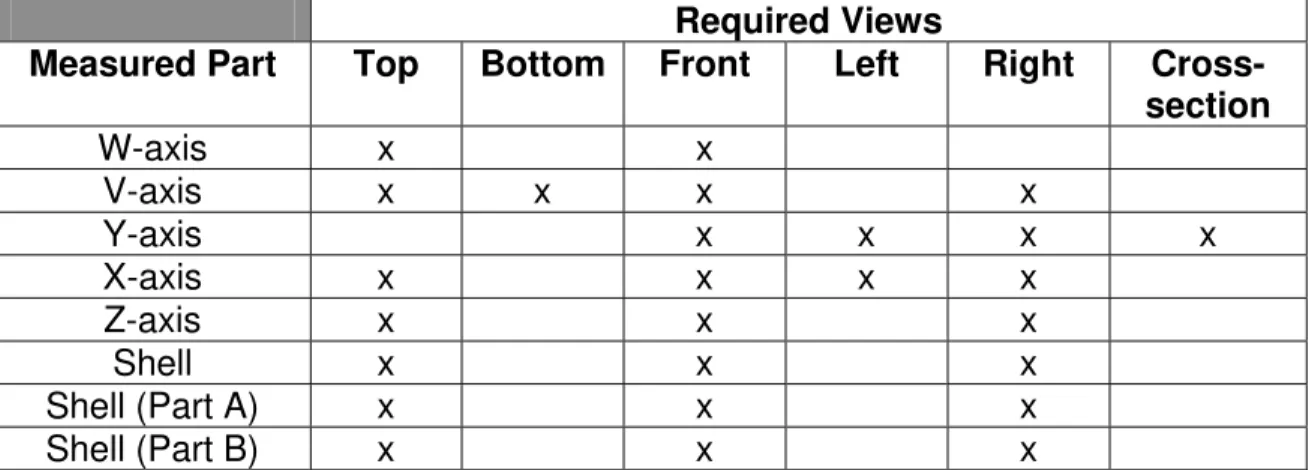
Table 2 shows all the views for each drawing.
Table 2. Required Views of the Drawings to Show all the Features of the Measured Parts
Required Views
Measured Part Top Bottom Front Left Right Cross-section W-axis x x V-axis x x x x Y-axis x x x x X-axis x x x x Z-axis x x x Shell x x x Shell (Part A) x x x Shell (Part B) x x x
4.3 Creation of the Measured Parts in AutoCAD
Photocopies of all the completed drawings are made so that the duplicates are clean and cannot be changed. The duplicates are used as the references for the creation of the measured parts in AutoCAD.
4.3.1 Example on How to Create the V-axis
The following shows the steps that should be taken and all the commands that should be performed in AutoCAD. The creation of the V-axis uses most of the AutoCAD features than the other axes. The V-axis is broken into three parts:
1. The main table.
2. The slants of the main table. 3. The cylinders.
The first phase in making the AutoCAD drawing is to draw the main table of the V-axis. 1. The main table
Command: box
<Corner of box> <0,0,0>: -70,-234,-89.5 <other corner>: 169.5,-73.6,0
2. The main table Command: box
<Corner of box> <0,0,0>: -70,-74,-65 <other corner>: 70,-3,0
3. From the menu bar, select Modify. Then select Boolean and Union. After that select the two boxes just created and click on the right mouse button to perform the operation.
4. The space under the main table Command: box
<Corner of box> <0,0,0>: -70,-145,-89.5 <other corner>: 134,-72,-65
5. From the menu bar, select Modify. Then select Boolean and Subtract. After that select the main table and click on the right mouse button. Then select the space under the main table and click on the right mouse button to perform the operation.
8
The second phase is to create the slants of the main table. 6. The slant on the top of the main table
Command: wedge
<Corner of wedge> <0,0,0>: -70,-234,0 <other corner>: -16.6,-473.5,0
Height: -28
7. From the menu bar, select Modify. Then select 3D Operation and Rotate 3D. Select the wedge created in the previous step and click on the right mouse button to perform the operation.
Axis by Object/Last/View/Xaxis/Yaxis/Zaxis/<2points>: z <0,0,0>: -70,-234,0
<Rotation angle>: 90
8. From the menu bar, select Modify. Then select Boolean and Subtract. After that select the main table and click on the right mouse button. Then select the rotated wedge in the previous step and click on the right mouse button to perform the operation.
9. The slant on the bottom of the main table Command: wedge
<Corner of wedge> <0,0,0>: -70,-234,-89.5 <other corner>: -49,-473.5,-89.5
Height: 11.5
10. From the menu bar, select Modify. Then select 3D Operation and Rotate 3D. Select the wedge created in the previous step and click on the right mouse button to perform the operation.
Axis by Object/Last/View/Xaxis/Yaxis/Zaxis/<2points>: z <0,0,0>: -70,-234,-89.5
<Rotation angle>: 90
11. From the menu bar, select Modify. Then select Boolean and Subtract. After that select the main table and click on the right mouse button. Then select the rotated wedge in the previous step and click on the right mouse button to perform the operation.
12. The slant on the bottom right side of the table Command: wedge
<Corner of wedge> <0,0,0>: 169.5,-72,-89.5 <other corner>: 119.5,-234,-89.5
13. From the menu bar, select Modify. Then select Boolean and Subtract. After that select the main table and click on the right mouse button. Then select the wedge created in the previous step and click on the right mouse button to perform the operation.
14. The slant on the right side of the table Command: wedge
<Corner of wedge> <0,0,0>: 169.5,-234,-89.5 <other corner>: 119.5,-333,-89.5
Height: 68.4
15. From the menu bar, select Modify. Then select 3D Operation and Rotate 3D. Select the wedge created in the previous step and click on the right mouse button to perform the operation.
Axis by Object/Last/View/Xaxis/Yaxis/Zaxis/<2points>: x <0,0,0>: 169.5,-234,-89.5
<Rotation angle>: -90
16. From the menu bar, select Modify. Then select Boolean and Subtract. After that select the main table and click on the right mouse button. Then select the wedge created in the previous step and click on the right mouse button to perform the operation.
The third phase in completing the V-axis is creating the cylinders. 17. The first cylinder from the space under the main table
Command: cylinder
<center point> <0,0,0>: 0,-92.5,-64 <Radius>: 47.5
<Height>: -14
18. The cylinder under the one in the previous step Command: cylinder
<center point> <0,0,0>: 0,-92.5,-77 <Radius>: 11
<Height>: -8
19. The cylinder under the one in the previous step Command: cylinder
10
20. The cylinder under the one in the previous step Command: cylinder
<center point> <0,0,0>: 0,-92.5,-87 <Radius>: 11
<Height>: -12
21. The cylinder under the one in the previous step Command: cylinder
<center point> <0,0,0>: 0,-92.5,-98 <Radius>: 6
<Height>: -7
22. From the menu bar, select Modify. Then select Boolean and Union. After that select all the cylinders and the main table and click on the right mouse button to perform the operation.
23. The cylinder on the back of the main table Command: cylinder
<center point> <0,0,0>: 0,-3,0 <Radius>: 72
<Height>: 3
24. From the menu bar, select Modify. Then select 3D Operation and Rotate 3D. Select the cylinder created in the previous step and click on the right mouse button to perform the operation.
Axis by Object/Last/View/Xaxis/Yaxis/Zaxis/<2points>: x Point on X axis <0,0,0>: 0,-3,0
<Rotation angle>: -90
25. From the menu bar, select Modify. Then select Boolean and Union. After that select the cylinder created in the previous step and the main table and click on the right mouse button to perform the operation.
The process of making the V-axis is completed. A folder called the v-axis is created. The AutoCAD file was saved as v-axis in the v-axis folder.
4.3.2 List of the AutoCAD Commands to Create Other Measured Parts
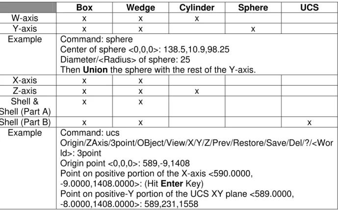
The procedures similar to Section 4.3 were used to create the other measured parts and the list of the commands required to create the other axes and the shell are shown in Table 3.
Table 3. List of the AutoCAD Commands to Create Other Measured Parts
Box Wedge Cylinder Sphere UCS
W-axis x x x
Y-axis x x x
Example Command: sphere
Center of sphere <0,0,0>: 138.5,10.9,98.25 Diameter/<Radius> of sphere: 25
Then Union the sphere with the rest of the Y-axis.
X-axis x x
Z-axis x x x
Shell &
Shell (Part A) x x
Shell (Part B) x x x
Example Command: ucs
Origin/ZAxis/3point/OBject/View/X/Y/Z/Prev/Restore/Save/Del/?/<Wor ld>: 3point
Origin point <0,0,0>: 589,-9,1408
Point on positive portion of the X-axis <590.0000, -9.0000,1408.0000>: (Hit Enter Key)
Point on positive-Y portion of the UCS XY plane <589.0000, -8.0000,1408.0000>: 589,231,1558
12
4.4 Creation of the Proteo Model D/94 in AutoCAD
Now that all the axes and the shell are drawn in AutoCAD. A D94 folder was created. Follow the instructions below to make a drawing that contains all the AutoCAD
drawings.
The first phase is to create seven layers for the AutoCAD drawing. 1. From the menu bar, select Format.
2. Then select Layer.
3. Click on the New button seven times to create seven layers. 4. Click the OK button.
The second phase is to insert the W-axis AutoCAD file into Layer1.
5. Select the Layer Control drop down menu (picture of a light bulb, sun, lock and a square) located in the tool bar under the menu bar.
6. Select Layer1.
7. From the menu bar, select Insert. 8. Then select Block.
9. Click on the File button.
10. Select Drawing File. Look for the W-axis AutoCAD file and Open it. 11. The options “Specify Parameters on Screen” and “Explode” should be
unchecked.
12. Specify Insertion Point X: 815 Y: 333 Z: 1109.5 for the W-axis. 13. Specify Scale X: 1 Y: 1 Z: 1.
14. Specify Rotation Angle: 0. 15. Click the OK button.
The third phase is to insert the other AutoCAD files into the other layers.
16. Repeat steps 5-15 for the V, Y, X and Z-axes, the Shell & Shell (Part A) and the Shell (Part B) by putting them into the appropriate layers. The following table has the insertion points for all the other parts.
Table 4. Axes Positions from Shell’s Reference Describing Machine’s Home Position
Axis Position (x,y,z) in millimetres
W (815, 333, 1109.5)
V (815, 425.5, 1080)
Y (815, 425.5, 1080)
X (735, 747, 941)
Z (594, 312.5, 1139)
Shell & Shell (Part A) (0,0,0)
Shell (Part B) (0,0,0)
By following the previous steps, all the axes and the shell should be together. The Z and X-axes should be on their tracks. The Y-axis should be mounted on the track of the X-axis. The V-axis should be attached to the Y-axis. Both the V and the Y-axes have the same centre point. The W-axis should be attached to the V-axis table.
14
5.0 Results
The drawings created as described in Section 4.2 are shown in Appendix A. A
colleague used these drawings to create the Java3D Proteo Model D/94. The purpose of this is to construct a model that can be put on an Internet page.
5.1 Screen Shots
The screen shots on the following pages are taken from the AutoCAD models and the 3DStudio animation of the Proteo Model D/94. Figures 3 to 11 are the finished
AutoCAD drawings. Another colleague used the AutoCAD Proteo Model D/94 [Fig.11] to create an animation of the D/94 from 3DStudio. Figures 12 and 13 are the screen shots from 3DStudio. Taking digital pictures and placing them on the AutoCAD file created the textures and colours of this model.
16
18
20
22
24
Figure 12. Proteo Model D/94, 3DStudio, Full View (Courtesy of Steve Kruithof)
Figure 13. Proteo Model D/94, 3DStudio, Close-up View (Courtesy of Steve Kruithof)
26
6.0 Recommendations
The following lists are for the future work on the modelling of the Proteo Model D/94. These parts should be modelled for simulation.
1. The drill bit.
2. The drill bit holder.
3. The slant from coordinates –65 to –89.5 on the V-axis [A.2]. 4. The door to the Shell (Part B) [A.8].
These parts can be added on for appearances. They are not necessary. 1. The shell’s curved surfaces.
2. The control panels.
3. The front drawer of the shell.
4. The front storing basin below the Z-axis.
7.0 Conclusion
The results of this project are the AutoCAD drawings. From these drawings, colleagues created a Java3D model and a 3DStudio model. These AutoCAD drawings provide NRC with a file of the Proteo Model D/94 for simulation and virtual reality. NRC might use this file for Internet purposes.
8.0 Reference
1. Barer-Proteo Model D/94
Ultra precision, mill/turn center for micro components, instruments & prototypes Barer ENGINEERING CO.
28
30
32
34


