A buckling flexure-based force-limiting mechanism
The MIT Faculty has made this article openly available.
Please share
how this access benefits you. Your story matters.
Citation
Slocum, Jonathan T. et al. "A buckling flexure-based force-limiting
mechanism." ASME 2018 International Design Engineering
Technical Conferences and Computers and Information in
Engineering Conference, Quebec, Canada, August 2018. © 2018
ASME
As Published
https://doi.org/10.1115/DETC2018-86388
Publisher
American Society of Mechanical Engineers
Version
Final published version
Citable link
https://hdl.handle.net/1721.1/128495
Terms of Use
Article is made available in accordance with the publisher's
policy and may be subject to US copyright law. Please refer to the
publisher's site for terms of use.
A BUCKLING FLEXURE-BASED FORCE-LIMITING MECHANISM
Jonathan T Slocum MIT1
Cambridge, MA, USA
Kenneth Kamrin MIT
Cambridge, MA, USA
Alexander H. Slocum MIT
Cambridge, MA, USA
ABSTRACT
A force-limiting buckling flexure has been created which can be used in a wide array of applications where excessive force from an implement can cause harm or damage. The buckling flexure is monolithic, contains no electronics, and can be manufactured using a single shot in an injection molding machine, making it extremely cost effective. In this paper, the design of this flexure is applied to a force-limiting toothbrush as an example of how this buckling flexure may be applied in a real-world technology. An overview of the buckling flexure is presented, and a structural model is shown to predict when the flexure will elastically buckle. This model is compared to data collected from flexures fabricated with varying buckling beam thickness. The data show that the force to buckle the flexure when applied at the tip can be predicted to within 20.84%. Furthermore, a preliminary model is presented which enables design of the buckling beam’s displacement, such that the total breakaway deformation can be maximized, making sensing the sudden deformation easier. As part of the application of the buckling flexure, an ergonomic, injection moldable toothbrush was created with the flexure built into the neck of the brush. When the user applies too much force while brushing, the flexure gives way and alerts the user when they have applied too much force and when the user lets off the force, the brush snaps back to its original shape. This design methodology is generalized and can be utilized in other force limited applications where an injection moldable, pre-set force, purely mechanical breakaway device is desired.
1. INTRODUCTION
Force-feedback and force-limitation are essential in sensitive operations such as surgery, handling of foods or produce, processes where people are interacting with robotics, and even dental hygiene [1–4]. In machinery, it is difficult to replicate this force feedback in a reliable and cheap manner
1 Current Affiliation: Materials and Engineering Group LLC, Belmont MA
without the need to sacrifice speed, simplicity, or productivity. For humans, this force feedback comes naturally and is developed through experience, however in the case of dental hygiene or cosmetics, excessive force can cause irreparable damage to sensitive tissues.
There exist many devices designed to provide this force-limitation or force feedback through sensors, breakaway couplings, or compliant mechanisms to name a few, however these methods either contain several moving parts or require the use of electronics to achieve force limitation [5–21]. This increases both cost and complexity which makes their application in disposable or low-cost devices limited.
Here we show a monolithic force-limiting flexure that buckles suddenly when excessive force is applied, but restores to its original shape when the force is relieved. At the point of buckling, there is a sudden change in shape of the flexure and an audible “click” is produced when the buckling beam strikes an anvil, both signals can be used to detect when excessive force is applied. The buckling flexure is monolithic and employs a twin-beam structure with an upper twin-beam that includes a nesting arch on its underside, and a lower buckling beam member which buckles when excessive force is applied to the tip; however, the buckling member (buckling beam) engages the nesting arch to form a stiff structure so the user or machine to operate if desired without risk of damaging the flexure or the machine. As the buckling flexure is a single piece, it can be manufactured at very low cost, making it ideal for applications where devices need force-limitation but thrown out after a single use. In this paper, the buckling flexure is analyzed and designed into the neck of a toothbrush since excessive force while brushing has been shown to harm dental tissue [4,22,23]. The presented analysis of the flexure is generalized even though it is in the neck of a toothbrush, thus it can be applied to design flexures for devices that need cheap and reliable force-limitation.
Proceedings of the ASME 2018 International Design Engineering Technical Conferences and Computers and Information in Engineering Conference IDETC/CIE 2018 August 26-29, 2018, Quebec City, Quebec, Canada
DETC2018-86388
NOMENCLATURE
A table of symbols can be found at the end of the paper. 2. BUCKLING FLEXURE DESIGN IN A TOOTHBRUSH
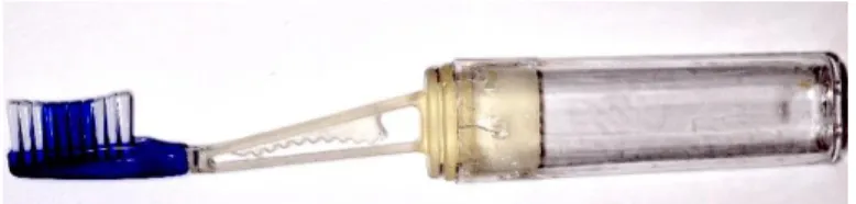
For this paper, the buckling flexure is designed into the neck of a toothbrush to limit the amount of force a user can exert while brushing. The force-limiting buckling flexure is shown in the neck of a toothbrush in Figure 1(a). The flexure will change state when a critical force (in this case from brushing teeth) is exceeded. There are three main elements of the flexure: the upper beam, the buckling beam which allows the structure to elastically buckle when too much force is applied, and the stiffening arch (anvil) which the buckling beam strikes to produce an audible click and prevent plastic deformation after buckling if the user continues to press harder. The user brushes their teeth as they normally would, the flexure only buckles as soon as too much force is applied while brushing, and until this point the brush exhibits normal stiffness.
The buckled shape of the flexure is shown in Figure 1(b) – the stiffening anvil is shaped to fit the shape of the buckling beam after excessive force is applied to the head. The stiffening anvil prevents further travel after buckling, thus maintaining the stiffness of the structure. There is area contact between the flexure and the anvil in order to reduce the unsupported length of the buckling beam, thus preventing second order buckling modes from occurring even if further excessive force is applied. During the design process and as models were tested, the area contact was observed to damp the ‘click’ as air and/or fluid was pushed out of the contact; hence the stiffening anvil surface was segmented with a ripple structure and a louder, more discernable click was then obtained when the buckling beam struck the anvil.
Figure 1(a): Toothbrush with buckling beam and
stiffening anvil to alert users when they are exerting too much force while brushing. Figure 1(b): close-up of the buckling flexure where the buckled beam is pressing against the stiffening anvil. The anvil serves three purposes: to provide an audible click when the buckling beam strikes, limit travel (and stress) in the buckled beam, and couple the two beams together to stiffen the structure post-buckling to ensure the device will not plastically deform or break. This protects both the user and the device from harm.
3. ANALYSIS
3.1. BUCKLING MODEL
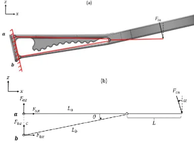
For modeling simplicity, the stiffness of the upper member is considered very large in comparison to the connecting nodes. Figure 2 (a) shows a simplified structure of the structure imprinted onto the neck of the toothbrush. Figure 2 (b) is the structure with labeled dimensions and angles that are relevant to the development of an analytical model. Figure 2 (c) shows the free-body diagram of the structure with component forces. For clarification, the segment La + Lis a continuous and treated as
rigid as well. The handle is treated as a rigid structure, for the force analysis only to determine the critical buckling load. The top beam is a single entity, which includes the upper beam (La).
The buckling beam (Lb) is treated as a two force member for
simplicity, thus the structure acts as a quasi-truss for the buckling load analysis.
To analyze how this structure will fail, the upper beam (La) and buckling beam (Lb) are connected with pin joints. It is
assumed that the force (Fin) is applied in the middle of the bristles
as a point load, not necessarily orthogonal to the buckling beam. The goal of this model is to resolve the axial forces inside the buckling beam (Fb) and upper beam (Fa) as a function of the
applied force and the geometry of the structure. From this the lower beam can be sized to buckle under a given compressive load, driven by the applied force.
Figure 2: (a) Shows the simplified structure imprinted
on the original brush, (b) is the structure with labeled dimensions and angles used in the following analysis as well as a free-body diagram of the structure with resultant forces.
An input normal force from brushing creates two resultant force components 𝐹1 and 𝐹2 at the head of the brush where the
bristles are. Resultant forces act at points a and b on the geometry shown in Figure 2 (c); equilibrium equations were generated (Eq. 1-3) resulting in three equations and four unknowns
( 𝐹𝑎𝑥, 𝐹𝑏𝑥, 𝐹𝑎𝑧, 𝐹𝑏𝑧). It is important to note that the boundary
conditions for the beams are assumed pinned and the internal moments thus negligible. In reality the molded plastic brush would have moment connections, not pin joints, but because of slender beams and connections, this simplification proves justified in order to develop a first order design analysis tool:
∑ 𝐹𝑥= 0 = 𝐹2+ 𝐹𝑎𝑥+ 𝐹𝑏𝑥 (1)
∑ 𝐹𝑧= 0 = 𝐹1+ 𝐹𝑎𝑧+ 𝐹𝑏𝑧 (2)
∑ 𝑀𝑦𝑎= 0 = −𝐹1(𝐿𝑎+ 𝐿) + 𝐹𝑏𝑥𝑐 (3)
The force in 𝐿𝑏 is axial, so it can be related to vector
components using nodal analysis (Eq. 4). Thus 𝐹𝑏𝑥 can be
expressed as a function of the angle 𝜃 of the buckling beam and the axial force in 𝐿𝑏 (𝐹𝑏). A new sum of moments is expressed
in terms of the internal axial force (Fb) of the buckling beam 𝐿𝑏
in Eq. 5.
𝐹𝑏 =
𝐹𝑏𝑥
cos 𝜃 (4)
∑ 𝑀𝑦𝑎= 0 = 𝐹𝑏c ∙ cos (𝜃) − 𝐹1(𝐿𝑎+ 𝐿) (5)
Using Eq. 5, the axial force 𝐹𝑏 in the buckling beam (𝐿𝑏)
can be expressed as a function of the input force and the structure geometry (Eq. 6).
𝐹𝑏 =
𝐹1(𝐿𝑎+ 𝐿)
𝑐 ∙ cos (𝜃) (6) Eq. 6 yields an expression for the axial force in the buckling beam as a function of the known input forces 𝐹1 and 𝐹2,
and the known geometry. The goal is to determine what input force 𝐹𝑖𝑛 (which is a function of 𝐹1 and 𝐹2) will cause the
structure to buckle; to do this 𝐹𝑏 is defined to be equal to the
critical buckling load of the buckling. Recall from Figure 1(b), the shape of the collapsed buckling beam is a cosine function. Since this beam is long and slender (slenderness ratio for all beam variations 𝜆 > 270), an Euler buckling model can be used. While the boundary conditions used in the Euler model to create a cosine shape are clamped on either end, in our model this provides the lower bound of the buckling force and the condition for buckling in the flexure can be expressed as 𝐹𝑏 being greater
than or equal to the calculated buckling load as predicted by the Euler model (Eq. 7).
𝐹𝑏−𝑏𝑢𝑐𝑘𝑙𝑒 ≥
𝜋2𝐸𝐼 𝑏
4𝐿2 (7)
The known minimum value of 𝐹𝑏 from Eq. 7 enables
calculation of a maximum input force 𝐹𝑖𝑛−𝑚𝑎𝑥 by relating 𝐹1 and
𝐹2 (Eq. 8), and using only geometric parameters of the beam.
These parameters can now be adjusted to reach the critical brushing force desired.
𝐹𝑖𝑛−𝑚𝑎𝑥= 𝜋2𝐸𝐼 𝑏 4𝐿2 (𝑐 cos 𝜃) cos 𝛼 (𝐿 + 𝐿𝑎) (8)
3.2. YIELDING OF BUCKLING BEAM
What has been shown is a predictive model for when the structure will fail. The next step is to calculate when the structure will yield, or rather calculate the maximum lateral displacement of the buckling beam so as to maximize the disturbance caused when too much force is applied. Though the model used to estimate the buckling force assumes a pinned-pinned boundary condition for the lower beam, the actual shape resembles a sinusoid, which is indicative of clamped-clamped boundary conditions. Thus, to start, the stress at buckling can be calculated for any clamped-clamped slender beam using Eq. 9 where
𝑟
is the radius of gyration of the structure.𝜎𝑐𝑟= 𝜋2𝐸 ( 2𝑟 𝑙𝑒𝑓 ) 2 (9) Solving for lateral displacement of buckled columns is well documented in Timoshenko’s “Theory of Elastic Stability” [24], where the primary example is a clamped beam with a free, unsupported end subjected to a point load (Figure 3). This column represents a quarter of a buckled column that has clamped-clamped boundary conditions, thus the total length of the column here has been adjusted to a quarter of the lower beam length.
Figure 3 – Large deflection of a slender buckled
column with clamped and free end boundary
conditions respectively. This represents ¼ of the total length of the buckling beam shape.
Since the lower beam deforms in the shape of a cosine function (Figure 4) - the goal is to determine the magnitude of
this function, as the shape is already assumed. From this, we can approximate the internal moment using basic beam theory.
Figure 4 – Deformed shape of the buckling beam – note
that it is the shape of a cosine function
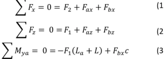
The shape of the function in Figure 4 is shown in Eq. 10. Timoshenko derives effectively half the magnitude 𝑘 of this deflection numerically by using the given geometry of the beam and solving for the deformed lengths using elliptical integrals. These integrals have already solved numerical solutions which Timoshenko displays values for the deformed magnitudes (Table 1). 𝑢(𝑥) = 𝑘(1 − cos (2𝜋𝑥 𝐿 ) (10
)
𝛆 20o 40o 60o 𝑃/𝑃𝑐𝑟 1.015 1.063 1.152 𝑥𝑎 (𝐿𝑏/2) 1.94 1.762 1.482 𝑦𝑎 (𝐿𝑏/2) 0.440 0.844 1.186 Table 1 – Values of the deformed shape for a givenangle at the inflection point of the cosine function. This table has been adjusted from Timoshenko’s original work to fit the current buckling beam
Thus if the lower beam was buckled to 20o at its inflection
point, using Table 1 and the length of the lower beam 𝐿𝑏 the peak
deflection would be 18.3 mm. It is important to note that this is significantly larger than any neck for any toothbrush. Thus this serves as an upper limit to what the flexure would ever need to be deformed to. This value is the magnitude 𝑘 of the deformed shape of the deflection so the internal moment can be approximated by differentiating the deflection (Eq. 10).
𝑀(𝑥) = −4𝜋 2𝑘 𝐿2𝑏 cos ( 2𝜋𝑥 𝐿𝑏 ) (11)
From this function, the maximum moment occurs at the clamped ends and in the middle of the beam. Thus the maximum bending stress (Eq. 11) can be solved using Eq. 10.
2 OMAX MICROMAX Precision Jet Machining Center:
https://www.omax.com/omax-waterjet/micromax
𝜎𝑚𝑎𝑥−𝑏𝑢𝑐𝑘𝑙𝑒 =
𝑀𝑚𝑎𝑥𝑡𝑏𝑒𝑎𝑚
2𝐼 (12)
The total moment inside the beam does not increase by more than 0.5 MPa for the thinnest structure, which is shown in Table 1 as a very small load increase will result in a large increase in deflection of the buckled shape. To compare, the stress in the upper beam can be compared to the stress in the lower beam. The stress in the upper beam can be approximated using deflection at the point where Fin is applied. Thus a cantilevered beam model
can be employed since the stress in the upper beam is only dependent on the deflection it has undergone. The force can be found as a function of the deflection and geometry (Eq. 13).
𝐹𝑐𝑎𝑛𝑡𝑖𝑙𝑒𝑣𝑒𝑟 =
3𝛿𝑡𝑖𝑝𝐸𝐼𝑎
(𝐿 + 𝐿𝑎)3 (13)
The maximum moment for a cantilever occurs at the base of the beam, thus the maximum stress experience by the upper beam can be calculated (Eq. 14). The stress shown here will be used to compare to the buckling stress computed in the results section. 𝜎𝑚𝑎𝑥−𝑎 = 𝐹𝑐𝑎𝑛𝑡𝑖𝑙𝑒𝑣𝑒𝑟(𝐿𝑎+ 𝐿)𝑡𝑎 2𝐼𝑎 (14) 4. METHODS
Test flexures were cut with an abrasive water jet2 from
6.25mm thick scratch-resistant polycarbonate (Figure 5); polycarbonate exhibits good elastic properties, minimizing hysteresis effects when the structure recovers from the buckled state. It is also similar in modulus to styrene-acrylonitrile, which is commonly used in manufacturing manual toothbrushes. Styrene-acrylonitrile is not readily available for manufacture of prototypes; thus it was more practical to use polycarbonate as a substitute. Six total samples were cut with buckling beam thicknesses varying from 0.9mm to 1.35mm to assess the validity and accuracy of the analytical model. Samples were also cut using representative dimensions for a standard toothbrush. Iterative testing was performed to determine brush geometries that yielded buckling forces due to brushing between 1 and 5N of force.
Figure 5 – A test buckling flexure cut from
clamped securely for force displacement testing. A notch was created a known distance from the flexure to ensure samples were repeatedly tested in the same position.
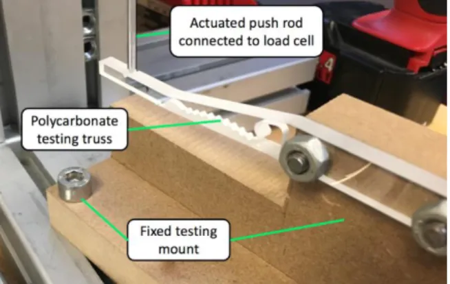
Test flexures with different buckling beam thicknesses were mounted in a fixed testing mount shown in Figure 6, and then deformed with an actuated load cell until the buckling beam completely conformed to the stiffening anvil. The testing machine pushed perpendicular to the notch of each beam of the flexure until the buckling beam conformed to the arch structure. This is the moment at which a user would likely stop brushing – all brush samples were pushed with at least 5N of force before the load cell was retracted. Pushing harder than the buckling force verified the design intent to have the buckled beam effectively connect with the upper beam by contact with the anvil.
Figure 6 - Test setup to deform the polycarbonate
testing flexures. Three main components allow the force-displacement of the buckling flexure to be measured: the testing flexure itself, a fixed testing mount, and an actuated load cell.
5. RESULTS
Since the moduli of polymers can vary depending on the batch of material that is used, the modulus of elasticity was measured by buckling against a scale a long, slender column (slenderness of 360) of material cut from the same stock as was used for the test flexures. A pinned-pinned Euler buckling model was used (Eq. 15). The average modulus for the polycarbonate from which the prototypes were cut was measured to be 2.58 +/- 0.03 GPa. A single beam was tested and 13 different measurements were taken.
𝐸 = 4𝐿
2𝐼
𝜋2𝐹 𝑚𝑒𝑎𝑠𝑢𝑟𝑒
(15)
Force-displacement data was collected using the setup shown in Figure 6. Buckling flexures with different buckling beam thicknesses were mounted and deformed past buckling. The distance between the stiffening anvil and the buckling beam was also kept constant so that the buckling beams across all
variations would have the same travel as they were deformed and buckled. The lower beam thicknesses were measured after manufacturing with the water-jet cutter. These data were plotted against one another to show how the critical load of the flexure increases as the lower beam thickness increases (Figure 7).
Figure 7 – Force-displacement data for test flexures
with different buckling beam thicknesses. Only one set of flexures with each thickness were measured. As beam thickness increases, the critical buckling load (first peak in the plots) of the structure also increases. Once the buckling beam conforms to the anvil, the structure stiffens again, as shown by the change of slope after approximately 3mm of displacement.
The first peak is when the buckling beam buckles – this is the critical buckling load, shown as the measured input force in Table 2. After buckling, the buckling beam strikes and mates with the stiffening arch of the upper beam. This measured critical load was compared to the predicted critical loads calculated using the previously derived model – these values are shown in Table 2. The total average error across all beam thicknesses between the measured input force and the predicted input force calculated using Eq. 8. is 20.84%.
Buckling Beam Thickness (mm) Measured Input Force (N) Model Predicted Force (N) Model Error 0.91 2.83 2.07 26.74% 1.04 3.52 3.15 13.30% 1.10 4.69 3.67 35.75% 1.22 5.54 5.08 16.03% 1.24 5.91 5.27 22.43%
1.34 7.04 6.73 10.78% Table 2 - Buckling beam thicknesses and
corresponding measured input force and predicted force values. As the beam gets thicker, the total amount of model error decreases. The average model error is 20.84%.
The stress at buckling in the lower beam for the flexures tested were calculated assuming an approximate yield of 60 MPa for polycarbonate (Table 3) using equation. With respect to the upper beam – the maximum stress sustained from 6mm of deflection (approximately the largest deflection all test samples underwent) is 34 MPa using equation 14.
Buckling Beam Thickness (mm) Slenderness Ratio Buckling Stress (MPa) % of yield stress 0.905 80 4.00 5.00% 1.04 69 5.28 6.60% 1.095 66 5.85 7.32% 1.22 59 7.27 9.08% 1.235 58 7.44 9.31% 1.34 54 8.76 10.96%
Table 3 – Approximate stress inside the flexure beams
at buckling. All of the columns are considered slender columns.
To determine the feasibility of the force-limiting structure in a real toothbrush, a buckling flexure was designed and printed to fit with a replaceable brush head and a compact travel toothbrush handle. The lower beam was tapered under than the anvil to help prevent pinching of any tissue inside the mouth when the flexure buckles. As the lower beam is tapered, the force to buckle it decreases linearly with the width. As the buckling force goes with the cube of the thickness, only a small increase in thickness is needed to accommodate of a moderate change in width of the buckling beam.
Figure 8 – Sample buckling flexure designed to mate
with a removable handle and toothbrush head. This flexure can be used for brushing and can be compactly stored
6. DISCUSSION
The model presented can predict the measured buckling load of the structure with an average 20.84% error across all beam thicknesses tested. The model assumes the structure is comprised of two-force members, which do not include any
resistive bending moments of the actual flexure elements. In actuality, the flexure deforms slightly and the upper beam does experience some bending that acts as an additional spring. This perhaps explains why the predicted input force for buckling the structure is lower than the actual measured amount. Indeed, not included in the model is the presence of an internal moment in the lower beam, which would make it behave like an imperfect column. Since the beam has clamped boundary conditions and the input force creates an applied moment on the structure, the column will require less force to buckle than if a single compressive force were applied. Both assumptions are potentially offsetting in the calculation as the simplified model presented here appears to be accurate enough to design the system and study how changes in various parameters buckling forces. In addition, the polymer itself is inherently a viscoelastic material, so thinner beams likely have increased variance in terms of their mechanical properties across the thickness of the beam.
Protecting the buckling beam and flexure structure during operation is an important feature - Figure 7 shows that the buckling beam strikes the stiffening anvil after buckling, which re-stiffens the structure. Thus if a user has buckled the structure and continues to press with increasing force, the mechanism is able to protect the user from causing failure of the structure as well as injury to the user. The stiffening anvil also exists as an actual anvil for the lower beam to strike, creating an audible signal that the structure has deformed and the peak brushing force has been reached.
In the case of a toothbrush the data shows that this structure will give way when less than 3N of force is applied, which is within the 1-4N threshold found to effectively remove plaque from teeth. What is not quantified in this study is how abruptly the structure buckles (buckling velocity) or any lateral displacement of the buckling beam. It also does not account for the dynamic movements associated with brushing and how the structure will respond while being used. For instance, lateral forces could also have an effect on buckling the flexure, if a compressive lateral force is applied to the structure as well a vertical brushing force (accounted for in the model) are applied, the flexure will likely buckle at a lower brushing force than is demonstrated in this paper. Further testing is warranted to evaluate these buckling modes.
7. CONCLUSION
A design for a buckling flexure for limiting applied forces has been presented where the flexure uses the principle of self-help to stiffen and strengthen after buckling to prevent damage. Design equations were developed into a predictive model to allow for sizing of members and studying effects of tolerances on performance. The buckling flexure design is demonstrate in a toothbrush handle as a force-limiter to improve a person’s ability to properly care for their teeth and gums. Exemplar flexure designs were tested and buckled with critical loads ranging from 2.83N to 7.04N achieved by changing only the thickness of the lower buckling beam. The predictive model, with an error of 20.84% from the measured critical load, can be
used to tune the mechanism to the desired stiffness and deterministically set tolerances for manufacture for applications outside the realm of dental hygiene. This design is monolithic, meaning that it can be injection molded in a single shot with no side pulls required. The use of the buckling flexure as a force-limiting device has use in other applications outside of toothbrushes, where excessive force can be damaging such as surgical tools, food-product handling robots, and human-interactive robots. The low-cost and simplicity of the design make it ideal for applications where the product is single use or needs to be low-cost in order to be competitive.
REFERENCES
[1] Krüger J, Lien TK, Verl A. Cooperation of human and machines in assembly lines. CIRP Ann - Manuf Technol 2009;58:628–46. doi:10.1016/j.cirp.2009.09.009. [2] De Santis A, Siciliano B, De Luca A, Bicchi A. An atlas
of physical human-robot interaction. Mech Mach Theory 2008;43:253–70.
doi:10.1016/j.mechmachtheory.2007.03.003.
[3] Zhang M, Laliberté T, Gosselin C. Design and Static Analysis of Elastic Force and Torque Limiting Devices for Safe Physical Human–Robot Interaction. J Mech Robot 2017;9:21003. doi:10.1115/1.4035683.
[4] Canadian Dental Hygienists Association. CDHA position paper on tooth brushing / déclaration de L’ACHD sur le brossage des dents. Can J Dent Hyg 2006;40:1–14.
[5] White L, Ingels L. Pressure Sensing Device for Holding a Toot. 4476604, 1984.
[6] Dirksing R. Toothbrush Having Handle Joined To Brush head by Non-Pinching Flexible Twin Beam Structure. 5105499, 1992.
[7] Kramer H. Toothbrush Comprising a Flexibly Linked Region in the Head. 6185779, 2001.
[8] Jungnickel U, Altmann N, Guebler R. Force Sensing Oral Care Instrument. 8832895, 2014. doi:10.1016/j.(73).
[9] Fox R, Hippen J, Knaub D, Resuello I, Frank P, Moskovich R. Replaceable Head Toothbrush Providing Controlled Brushing Pressure. 6502272, 2003. doi:10.1021/n10602701.
[10] Giuliani D, McMahohn RW, McInnes C. Toothbrush With Adaptive Load Sensor. 5784742, 1998.
[11] Huefner NF, Burrell FJ. Toothbrush Having Adjustable Brushing Pressure. 5315732, 1994.
[12] Heinzelman BD, Lamond DR, Fontayne D. Resiliently Flexible Toothbrush. 5735012, 1998.
[13] Sundius CL, Mcfadden BP. Pressure Sensing Toothbrush. 5876207, 1999.
[14] Mierau H-D, Spindler T. Toothbrush. 4698869, 1987. [15] Piserchio R. Pressure-Sensitive Toothbrush. 12/506951,
2011.
[16] Irizarry J. Pressure Alarm Toothbrush Assembly.
5331707, 1994.
[17] Craig JJ. Hybrid Position / Force Control of. J Dyn Syst Meas Control 1981;102:126–33. doi:10.1115/1.3139652.
[18] Daniel E. Force Feedback Bontml oi Manipulator Fine Motions 2008.
[19] Rosenberg LB, Jackson BG. FORCE FEEDBACK DEVICE INCLUDING FLEXURE MEMBER BETWEEN ACTUATOR AND USER OBJECT. 6,437,771, 2002. doi:10.1016/j.(73).
[20] Das H, Ohm TR, Steele RD. TOOL ACTUATION AND FORCE FEEDBACK ON ROBOT-ASSISTED MICROSURGERY SYSTEM. 6,385,509, 2002. doi:10.1016/j.(73).
[21] Pierrot F, Dombre E, Dégoulange E, Urbain L, Caron P, Boudet S, et al. Hippocrate: A safe robot arm for medical applications with force feedback. Med Image Anal 1999;3:285–300. doi:10.1016/S1361-8415(99)80025-5. [22] Rosema NAM, Adam R, Grender JM, Van der Sluijs E, Supranoto SC, Van der Weijden GA. Gingival abrasion and recession in manual and oscillating-rotating power brush users. Int J Dent Hyg 2014;12:257–66. doi:10.1111/idh.12085.
[23] Löe H. Oral hygiene in the prevention of caries and periodontal disease. Int Dent J 2000;50:129–39. doi:10.1111/j.1875-595X.2000.tb00553.x.
[24] Timoshenko S. Theory of Elastic Stability. First Edit. New York and London: McGraw-Hill Book Company Inc.; 1936.
TABLE OF SYMBOLS 𝐹𝑖𝑛 Input force from user
𝐹𝑎𝑥 x-direction reaction force at 𝑎
𝐹𝑎𝑧 z-direction reaction force at 𝑎
𝐹𝑏𝑥 x-direction reaction force at 𝑏
𝐹𝑏𝑧 z-direction reaction force at 𝑏
𝐿 Distance from brush head to flexure
𝐿𝑎 Upper beam length
𝐿𝑏 Buckling (lower) beam length
𝑎 Upper beam node
𝑏 Buckling beam node
𝑐 Distance between node a and b
𝑡𝑏𝑒𝑎𝑚 Thickness
𝛼 Angle of input force on structure
𝜃 Angle between 𝐿𝑎 and 𝐿𝑏
𝐼𝑎 Moment of Inertia of upper beam
𝐼𝑏 Moment of inertia of buckling beam
𝐸 Modulus of elasticity
𝜆 Slenderness ratio
𝑙𝑏−𝑒𝑓𝑓 Effective length of buckled beam
𝜀 Slope at inflection point of buckled shape
𝑃𝑎 Load on buckled shape (𝐹𝑏 𝑖𝑠 𝑢𝑠𝑒𝑑)
𝑧𝑎 Lateral displacement of buckled beam