Publisher’s version / Version de l'éditeur:
Electronic Journal of Information Technology in Construction, 8, pp. 119-134,
2003-07-01
READ THESE TERMS AND CONDITIONS CAREFULLY BEFORE USING THIS WEBSITE.
https://nrc-publications.canada.ca/eng/copyright
Vous avez des questions? Nous pouvons vous aider. Pour communiquer directement avec un auteur, consultez la première page de la revue dans laquelle son article a été publié afin de trouver ses coordonnées. Si vous n’arrivez pas à les repérer, communiquez avec nous à [email protected].
Questions? Contact the NRC Publications Archive team at
[email protected]. If you wish to email the authors directly, please see the first page of the publication for their contact information.
NRC Publications Archive
Archives des publications du CNRC
This publication could be one of several versions: author’s original, accepted manuscript or the publisher’s version. / La version de cette publication peut être l’une des suivantes : la version prépublication de l’auteur, la version acceptée du manuscrit ou la version de l’éditeur.
Access and use of this website and the material on it are subject to the Terms and Conditions set forth at
Implementation of distributed model-based integrated asset
management system
Hassanain, M. A.; Froese, T. M.; Vanier, D. J.
https://publications-cnrc.canada.ca/fra/droits
L’accès à ce site Web et l’utilisation de son contenu sont assujettis aux conditions présentées dans le site
LISEZ CES CONDITIONS ATTENTIVEMENT AVANT D’UTILISER CE SITE WEB.
NRC Publications Record / Notice d'Archives des publications de CNRC:
https://nrc-publications.canada.ca/eng/view/object/?id=02a2cd08-fc0b-4232-8d33-d342cf58b27c https://publications-cnrc.canada.ca/fra/voir/objet/?id=02a2cd08-fc0b-4232-8d33-d342cf58b27cImplementation of a distributed, model-based
integrated asset management system
Hassanain, M.A.; Froese, T.M.; Vanier, D.J.
NRCC-46394
A version of this document is published in / Une version de ce document se trouve dans: ITCon, Electronic Journal of Information Technology in Construction, v. 8, 2003, pp. 119-134
IMPLEMENTATION OF A DISTRIBUTED, MODEL-BASED
INTEGRATED ASSET MANAGEMENT SYSTEM
SUBMITTED: September 2003 REVISED: June 2003
PUBLISHED: July 2003 at http://www.itcon.org/2003/10 EDITOR: Bo-Christer Björk
Mohammad A. Hassanain, PhD, Assistant Professor
King Fahd University of Petroleum and Minerals, Kingdom of Saudi Arabia email: [email protected]
Thomas M. Froese, PhD, Associate Professor University of British Columbia, Canada email:[email protected]
Dana J. Vanier, PhD, Senior Research Officer National Research Council Canada, Canada email: [email protected]
SUMMARY: This paper presents the development of a generic framework for asset maintenance
management, and an object model for the maintenance management of roofing systems as a case study to demonstrate the applicability of the framework. The model builds upon the Industry Foundation Classes (IFCs) to define object requirements and relationships for the exchange and sharing of maintenance information between applications. The paper explores the implementation of the developed maintenance management models through the development of a distributed, model-based integrated system. It describes the set of inter-connecting components forming a typical or reference system architecture for integrated distributed systems. It describes the Jigsaw Distributed System (JDS) version 0.6, as the implementation environment of the reference architecture, which facilitates a wide range of data exchanges and software interoperability. The paper describes the development of a generic Asset Management Tool (AMT) prototype data client application that can initiate data exchanges with a number of data servers (including MicroROOFER, Microsoft Project, and files that can be used by several other applications), thus demonstrating software interoperability in the
Facilities Management (FM) domain. Finally the paper presents an evaluation and testing scenario for the prototype application.
KEYWORDS: Asset Management, IFC, Model-Based Distributed Systems, Asset Management Tool
1. INTRODUCTION
In a review of the state-of-the-art in asset management (AM), operational knowledge for the practice of AM was found to exist within literature, current software, and current practice. This body of knowledge appears to be less well developed than areas such as project and construction management (e.g., as observed by the relative number and range of books and scholarly literature in these areas). Some efforts were found to formalize AM knowledge and practice in models, but these were found to be few and partial in their coverage of the breadth and depth of AM concerns. One of the research challenges addressed in this paper was to synthesize the available knowledge sources into a formal model for the practice of maintenance management. The primary motivation for this was the development of IT tools for asset management, but the resulting formalization also offers other benefits in structuring the organization and management of AM knowledge and operations.
AM is currently a young and growing, yet still a fragmented industry. One of the contributing factors to this fragmentation is that the AM industry is witnessing a proliferation of software tools (Vanier 2001). Furthermore, each of these software tools is providing standalone solutions to a multitude of problem areas, such as asset inventory, condition assessment and strategic planning. As a result, there exist many data format and databases, leading to large volumes of loosely-structured data (Kyle et al. 2000; Peters and Meissner 1995) with poor interoperability. Moreover, no software solutions were found that
exchange data interoperably between corporate desktop computer applications. This interoperability holds the promise of reducing dependency on paper-based views of both project and asset information. Data model standards are a way of representing technical and administrative information content, leading to the development of data structures that allow information to be exchanged among various computer applications (Eastman 1999). A requirement to achieve integration is conformance to some degree of standardization of the information representation approaches. Efforts in this line of research include those under ISO International Standard 10303, STEP (Standard for the exchange of product model data) (ISO 1994), or the Industry Foundation Classes (IFCs) developed within the International Alliance for Interoperability (IAI) (IAI 1999).
This paper reviews the development of a generic framework for asset maintenance management, and an object model for the maintenance management as a case study to demonstrate the applicability of the framework. The paper then explores the implementation of the developed asset maintenance
management models through the development of a distributed, model-based integrated system. It describes the set of inter-connecting components forming a typical or reference system architecture for integrated distributed systems. It describes how the Jigsaw Distributed System (JDS) version 0.6 (JDS 2001), the implementation environment of the reference architecture, is used to facilitate a wide range of data exchanges and software interoperability. The paper then describes the development of a generic Asset Management Tool (AMT) prototype data client (DC) application that can initiate data exchanges with a number of data servers (DS), thus demonstrating software interoperability in the Facilities Management (FM) domain. Finally the paper presents an evaluation and testing scenario for the prototype application.
2. GENERIC ASSET MANAGEMENT MODELS
This section reviews briefly the development of an integrated framework model for asset maintenance management (Hassanain et al. 2001). Development of this framework was motivated by the desire to develop IT solutions for the FM industry. However, the framework is useful beyond its role in supporting IT. The framework, presented as an IDEF0 (Integration Definition for Function Modeling)
process model as shown in Fig. 1. In IDEF0 notation, boxes represent tasks while arrows from the left,
right, top and bottom represent inputs, outputs, controls, and mechanisms, respectively. The framework is generic, meaning that the activities involved can be applied to non-specific assets. Further, the framework can be applied at both the level of individual assets or on a network of assets. The
framework can also be used to analyze current maintenance management practices in FM organizations engaged in managing several assets, regardless of whether the tasks involved are implemented by in-house staff or professional maintenance contractors.
The framework model is unique in the sense that it is a collection of diverse knowledge areas that have been analyzed and introduced to the FM domain in a formalized and standardized view. The framework model consists of five sequential processes. It starts with carrying out an inventory of all assets
requiring maintenance during their service life and ends with scheduling maintenance operations. For each of the processes, the authors have defined a number of supporting activities, with their logical sequences and information requirements (Hassanain 2002).
3. INTEGRATED MAINTENANCE MANAGEMENT MODELS
The purpose of developing a process model is to define requirements for information sharing amongst the various asset management areas. Within the AEC domain, a large-scale effort is underway to create a general purpose data model, the IFCs, for information exchange throughout the project life cycle. Some FM domain knowledge has been incorporated into the current release of the IFCs, but to date, there has been virtually no assessment and validation of how well the IFCs can support maintenance management.
In developing the asset maintenance information models (Hassanain et al. 2001), and in keeping with the notion of developing integrated maintenance project models, the authors chose to conform to the development methodology set out by the IAI. The IAI is a global, non-profit, industry-based consortium for the AEC/FM industry (IAI 2000). The IAI was established with the objective of defining, publishing and promoting a specification (the IFCs) which describes building objects in a neutral computer language that represents information requirements common to all industry processes. The goal of the IAI is to enable interoperability among industry processes of all different professional
domains in AEC/FM projects by allowing the computer applications used by all project participants to share and exchange project information. The scope of the IAI is the entire life cycle of the building, covering strategic planning, design and engineering, construction, and building operation.
A Identify Assets R Identify Performance Requirements P Assess Performance M Plan Maintenance O Manage Maintenance Operations Provided Facility Resources Operational Facility Asset Register
As-built Records Initial Design Parameters Occupancy Characterstics
Performance Agents
Assessment Methodology - Inspection Targets - Inspection Type
- Inspection Frequency Conflicting Objectives - Minimize Cost - Minimize Risk of Failure - Maximize Performance Budget Time Facility Management Team Assets Requiring Maintenance Statement of Performance Requirements Performance Values Statement of Asset/ Component Condition Maintenance Work Order
Figure 1: General processes involved in maintenance management model
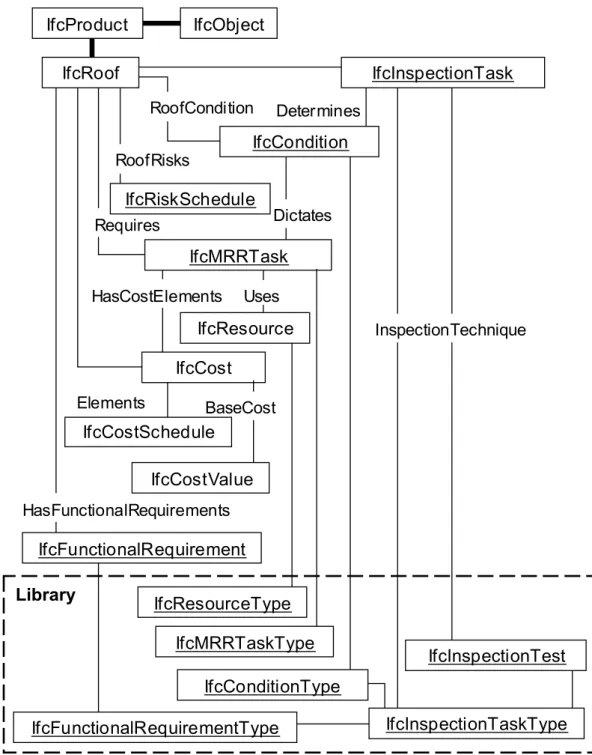
The formulation of the proposed framework led to an iterative development of data models for representing the information that will be exchanged among all participants in an asset maintenance management project. These data models build upon the IFCs to define object requirements and relationships for the exchange and sharing of maintenance information between applications. Roofing systems, especially flat or low-slope conventional assemblies, were chosen as a "proof of concept" building system that is representative of the built-asset maintenance domain. Fig. 2 provides a class diagram for the proposed roofing maintenance management model. A set of proposed IFC data
standards has been generated that considered existing standards and representations in IFCs Release 2X and recommendations have been made for a number of extensions for inclusions in Release 3.0
(Hassanain et al. 2001); however, these will not be discussed in this paper. The focus here is on the reference system architecture, the implementation environment of that architecture, and the
development of a generic AMT prototype, which attempts to facilitate a wide range of data exchanges and software interoperability in the FM domain.
Determines
Library
IfcObject
IfcInspectionTaskType
IfcInspectionTest
RoofCondition RoofRisks Requires Uses DictatesIfcMRRTask
HasCostElementsIfcCost
Elements BaseCost HasFunctionalRequirementsIfcCostValue
IfcFunctionalRequirementType
IfcFunctionalRequirement
IfcCostSchedule
IfcResource
IfcResourceType
IfcRiskSchedule
IfcInspectionTask
IfcMRRTaskType
IfcConditionType
InspectionTechniqueIfcCondition
IfcProduct
IfcRoof
Figure 2: Overview of roofing maintenance management data model
4. DISTRIBUTED SYSTEMS AND ARCHITECTURE
The prototype implementation reported upon in this paper is centered on developing a data client (DC) component that interacts with a number of data server (DS) components, through a standard
Application Programming Interface (API). The custom-built DC component, described later within this paper, is named Asset Management Tool (AMT), while the implementation environment selected for the distributed system architecture is named Jigsaw Distributed System version 0.6 (JDS 2001).
4.1 The jigsaw distributed system (JDS)
The JDS, developed as a parallel research endeavour (JDS 2001), aims at creating tools to support both project model-based data integration and transaction-based application interoperability. The JDS implements a general reference architecture by creating a system in which a wide variety of DCs can
communicate with a wide variety of DSs through a standard API, so that individual DCs need not know the details of the individual DSs and vise-versa.
4.1.1 Data Clients (DCs)
DC applications interact and initiate data exchanges with DS applications through a number of data import/export operations, typically initiated from within the user interface of that of the DC application. DC applications typically are custom-built applications, or current, desktop applications, referred to as “legacy applications” that work with their own application data. Data exchanges within the JDS are facilitated through abstract components called “adaptors”. Adaptors map the schema of the DC application to the Jigsaw data interface.
4.1.2 Jigsaw Interface
The standardized Jigsaw interface uses many "industry standard" elements, namely, Extensible Markup Language (XML) and the XML Document Object Model (DOM) for the "data content" API, and uses the IFCs for much of the data content schema. Jigsaw adds some custom elements for the data access and control API, and some extensions to the IFC schemas. The Jigsaw data server Application Programming Interface is called JsServerDOM (shown in Fig. 3). The JsServerDOM is an “abstract” component: it defines the interface for all Jigsaw data server components.
Data Server
JsServerDOM
Data Source
Data Source - Specific API
Client
Data
Files
Data Client
Figure 3: Jigsaw Distributed System client-server interaction
Application
Application
Data Client
Database
WWW
XML
File
Adaptor
Adaptor
Adaptor
Adaptor
Standard
Jigsaw data
Interface
Adaptor
App
Data
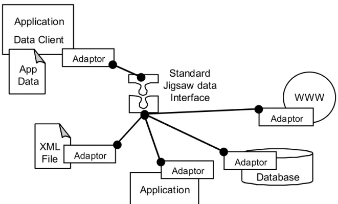
As Fig. 3 illustrates in a typical Jigsaw situation, a DC can work with its own client data, but it uses the JsServerDOM interface for all interactions with other applications or data sources. These data requests can be for full models or for specific pieces of information. The Jigsaw data server provides a
"wrapper" around some other form of data source, adapting it to the JsServerDOM API.
4.1.3 Data Servers (DSs)
Current types of DSs are illustrated schematically in Fig. 4. The standard Jigsaw data interface can respond to information requests (data exchanges) for either full data models or specific pieces of information, include: XML files, Building Lifecycle Interoperable Software (BLIS) IFC data files. Other legacy applications such as Microsoft Project and MicroROOFER, relational databases, and remote data sources on the World Wide Web can also be accessed.
5. A TIERED REFERENCE ARCHITECTURE
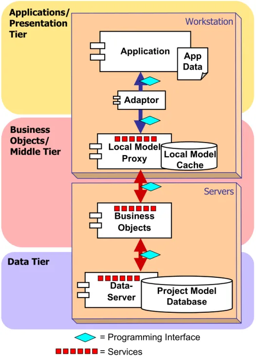
Jigsaw is implemented in a three-tiered reference architecture as proposed by Froese (Froese et al. 2000). Fig. 5 illustrates a typical set of software components for the distributed, model-based, integrated system for AEC/FM. These components describe a typical, or reference architecture. One possible configuration is where these logical tiers consist of two or more physical computer systems (i.e. a user’s workstation and one or more central servers). The listing below describes the system components within each tier as:
• The applications/presentation tier: contains application programs and related user-centric components. This paper is focusing on implementation work within the application tier, where the prototype AMT represents a custom-built application that has the capability to import and export data files from other legacy applications. For example, the AMT was developed using Microsoft Visual Basic 6.0. In the application or presentation tier, both custom-built and legacy system applications maintain their own data sets in addition to the information shared through the integrated system. Adaptors, as illustrated in Fig. 5, are pieces of code that serve to map application schema to the common data schema. This mapping is carried out by an application-specific adaptor software component.
• The business objects/middle tier: brings the data and services from the data tier to the local applications and implements business logic processes of the
applications/presentation tier. In this configuration, local model proxies are software components on users’ workstations. Applications and adaptors access a local version of the shared data that acts as a proxy for remote data sources. These components expose the distributed information services to client applications, and handle the communication of the local data within the distributed servers.
• The data tier: handles the persistence of project model data. While there can be various centralized or distributed data repository alternatives, a typical configuration involves a central database and DS component that interacts with model proxy components across the Internet/Intranet connection.
Data Tier
Business
Objects/
Middle Tier
Applications/
Presentation
Tier
Workstation
Application
Local Model
Proxy
Adaptor
Servers
Data-Server
Project Model
Database
App
Data
= Programming Interface
= Services
Local Model
Cache
Business
Objects
Figure 5: A reference architecture for a distributed, model-based, integrated system (Froese et al. 2000)
6.ASSET MANAGEMENT TOOL, A PROTOTYPE INTEGRATED
APPLICATION
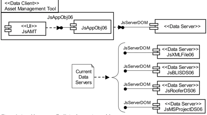
The AMT is a prototype application that implements generic asset management in a distributed, model-based, integrated AEC/FM environment. The AMT is a custom-built application, implemented as a Jigsaw data client, situated within the application/ presentation tier of the reference-system architecture described in the section above. Fig. 6 illustrates the AMT prototype application in Unified Modeling Language (UML) notation and shows the interaction of the DC software components (Jigsaw Asset Management Tool and Jigsaw Application Objects) with data server software components (Jigsaw XML file, Jigsaw BLIS data source, Jigsaw MicroROOFER data source and Jigsaw Microsoft Project data source) through a standard Jigsaw data interface. The following listing provides a description of the DC and DS software components involved in the implementation of the AMT prototype
<<Data Server>> JsBLISDS06 <<Data Server>> JsRooferDS06 <<Data Server>> JsXMLFile06 <<Data Server>> JsMSProjectDS06 <<UI>> JsAMT JsAppObj06 <<Data Server>> JsServerDOM JsAppObj06 JsServerDOM JsServerDOM JsServerDOM JsServerDOM Current Data Servers <<Data Client>>
Asset Management Tool
Figure 6: Asset Management Tool’s implementation model
6.1 Data Client Software Components
The two main DC components of the prototype application include the user interface components of the Jigsaw AMT and the set of Application Objects for the implemented schema.
6.1.1 Jigsaw Asset Management Tool
The Jigsaw AMT "JsAMT" is a custom-built application consisting of Visual Basic user interface forms and code through which the user interacts with project data and initiates a wide range of data exchanges.
6.1.2 Jigsaw Application Objects
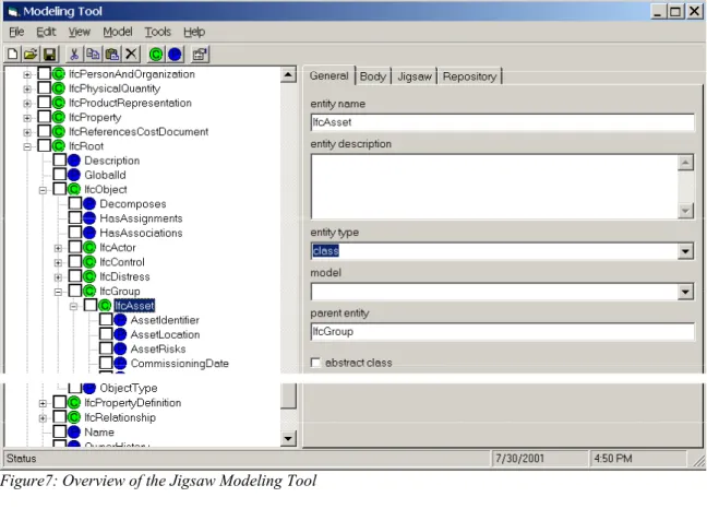
The Jigsaw Application Objects “JsAppObjs06” component is a dynamic, customized data model component, generic to the DCs implemented within the JDS. The Jigsaw Application Objects consist of Microsoft Visual Basic classes that implement a collective schema encompassing all objects necessary for all DCs in the JDS. These Microsoft Visual Basic classes are generated automatically using an independent utility called the Jigsaw Modeling Tool (JMT), shown in Fig. 7. The set of specific IFCs supporting the asset maintenance management data model, along with other IFCs supporting other data models intended for implementation within the JDS, are available and can be edited by the user through this user interface. Since the JMT can import and export various forms of models (i.e., models with different meta-models), it acts as a "meta-meta model". Fig. 7 illustrates a snapshot of the collective IFC schema for all data client components, defined and edited using the JMT’s user interface. In Fig. 7 the schema is displayed through an explorer-style interface that provides the user with the visual ability to browse through individual classes within the IFC schema. The user can view the properties of a particular class in the explorer-style interface through either expanding the node of the class, or double-clicking on that class. The user can also view and/or edit the entity name, description, type, etc. on the tabs view to the right of the explorer-style interface. Fig. 8 illustrates the operation of creating Jigsaw application objects (Microsoft Visual Basic code) for all objects defined within the data model.
Figure7: Overview of the Jigsaw Modeling Tool
Figure 8: Creating Jigsaw application objects
6.2 Data Server Software Components
In addition to the existing DS components which can include XML files, BLIS data sources, MicroROOFER data sources and Microsoft Project data sources, the AMT prototype application is capable of exchanging data through the standard Jigsaw interface with any other application that works with a similar information structure”, as illustrated in Fig. 6.
6.2.1 Jigsaw Server Document Object Model
The Jigsaw Server Document Object Model “JsServerDOMis an “abstract” component that defines the interface for all Jigsaw data server components.
6.2.2 Jigsaw XML File
The JsXMLfile06 DS component can read or write data as XML files. In importing XML files, information that is supported through the application’s schema is imported, while unsupported information is simply ignored.
6.2.3 Jigsaw BLIS Data Source
Building Lifecycle Interoperable Software (BLIS) is a group of software developers who are members in the consortium of the IAI, with the mission to develop interoperable prototype software to validate the use of the IFCs (BLIS 2001). The JsBLISDS06 DS component, shown in Fig. 6, can read and write from IFC 2.0 data files as used by software applications from the BLIS project. At present IFC 2.0 data sources undergo a partial mapping to the IFC 2X schema.
6.2.4 Jigsaw MicroROOFER Data Source
The JsRooferDS06 DS allows the user to import and export roof building product objects from the MicroROOFER application.
6.2.5 Jigsaw Microsoft Project
Figure 9: Overview of the Asset Management Tool’s user interface populated with data for project 327
Data Source
The JsMSProjectDS06 DS component allows the user to import and export tasks information, such as task name, duration, start date, finish date, predecessor and successor tasks from Microsoft Project files.
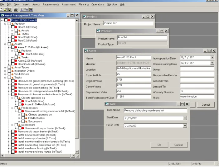
An integral part of the developed AMT prototype application is the user interface. Two main user interface components have been used to provide the required functionality for the user to browse, input and edit project information. These components are a “Tree View” explorer and Multiple-Document Interface forms shown in Fig. 9.
The explorer-style “Tree view” interface provides the application user with the visual ability to locate a project’s data records in potentially large data collections. It provides a visual display of the hierarchy of a single project in the database and the association between various different objects in the
hierarchy. In essence, the “Asset Management Tree View” explorer brings up a view of the
implemented data model, thus providing the user with a multi-dimensional view of the data model and the instantiated objects in the database. For example, the user can follow the "Assets" tree in Fig. 9 down to the "Roof" object.
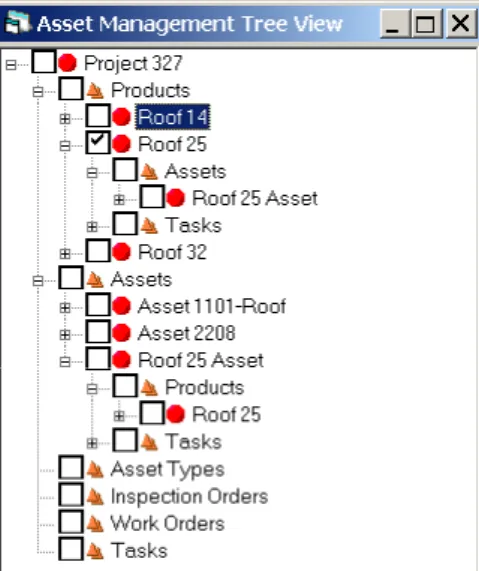
The two icons and are used in the project hierarchy to denote “Objects” and “Collections” respectively. Any new project has the following implemented object collections, as displayed in Fig. 9:
1. Products: every object in the “Products” collection can have association with the following two object collections.
• Assets: a collection of asset objects that can be treated as building products. • Tasks: a collection of task objects that can be associated with products.
2. Assets: every object in the “Assets” collection can have association with the following two object collections.
• Products: a collection of product objects that can be treated as assets. • Tasks: a collection of task objects that can be associated with assets.
3. Tasks: every object in the “Tasks” collection can have association with the following three object collections.
• Objects operated on: a collection of objects on which a particular task operates. • Predecessors: a collection of predecessor task objects.
• Successors: a collection of successor task objects.
Data for each object in the hierarchy can be edited in the database by double clicking on the appropriate object within its collection in the explorer and viewing the appropriate Multiple-Document Interface form, as shown in the right hand side of Fig. 9. The Multiple-Document Interface forms-style interface allows the user to display multiple forms at the same time; each form is displayed in its own window. The user can interact with AMT through browsing structured project information in the hierarchy, creating and/or editing object data records belonging to the appropriate collection in the project hierarchy, and importing/exporting data from and to other data sources. Importing/exporting refers to the user’s ability to send off and bring in data records to and from data servers, respectively. The AMT can currently export and import data records to and from four types of data sources within the Jigsaw Distributed System:
1. XML file data server, referred to as JsXMLFile06. 2. Ifc2.0 file data server, referred to as JsBLISDS06.
3. MicroROOFER database data server, referred to as JsRooferDS06. 4. Microsoft Project file data server, referred to JsMSProjDS06.
Not only can AMT interact with the applications for which data server adaptors have been created (MicroROOFER and Microsoft Project), but it can also interact with any other applications that can work with any of these data sources, such as programs from the BLIS group that can read and write Ifc2.0 files (BLIS 2001).
8. EVALUATIONS AND TESTING SCENARIO
Project-information examples were used to serve dual purposes. The first tested the user interface browsing and editing capabilities. The second validated the structure of the developed asset
management data model (Hassanain et al. 2001). The scenario below presents a progression of steps that describes how the AMT can be used to achieve software interoperability. It must be stressed that the focus of the implementation was not to develop software with features already available in commercially available software. The focus was rather to implement a distributed model-based,
integrated prototype application that combines building product and process information and is capable of data exchange.
8.1
Starting from Scratch
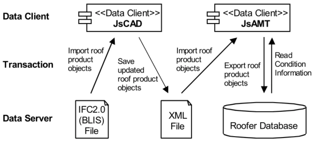
Starting with an empty project, the user populates the “Products” collection in the AMT application with roof objects. The user can also choose to import roof product objects into the “Products” collection of the AMT application from one or a combination of data sources. Moreover, the user can also import roof product data records in an XML file format from a currently developed CAD application, acting as another DC component within the Jigsaw system. The JDS includes a CAD application referred to as JsCAD. Fig. 10 illustrates schematically the DC and DS components involved in populating the AMT application with roof product objects from scratch.
IFC2.0 (BLIS) File <<Data Client>> JsAMT <<Data Client>> JsCAD XML
File Roofer Database
Import roof product
objects Save updated
roof product objects
Import roof product
objects Export roof
product objects
Data Client
Data Server
Transaction Read Condition
Information
Figure 10: Populating the Asset Management Tool application with roof product objects from scratch
8.2 Creating Association Relationships between Objects
The user can then populate the “Assets” collection in the AMT application with asset objects. The intent here is to define generic data, entered in the “Asset” data entry form, for the “Product” object. An association relationship between the two objects can then be established within the project
hierarchy (e.g. a roof object and an asset object). This is facilitated using the user interface by dragging the roof product object from its “Products” collection and dropping it on the appropriate asset object in the “Assets” collection. Fig. 11 illustrates associating “Roof 14” product object within the “Products” collection to “Asset 1101 – Roof” asset object in the “Assets” collection.
The user can also create an asset object from a particular roof product object. Fig. 12 illustrates creating “Roof 25 Asset” object in the “Assets” collection from “Roof 25” product object within the “Products” collection.
Figure 12: Creating “Roof 25 Asset” asset object from “Roof 25” product object
8.3 Exporting Data to MicroROOFER Application
The process of exporting the three roof product objects from the AMT application to the
MicroROOFER application starts with setting the data source type to “JsRooferDS06”. The user is then prompted to save the project file by either replacing a file for an existing project, or to add the project file to an existing project file (as illustrated schematically in Fig. 6). (At the time of composing this evaluation and testing scenario, exporting roof product objects to the MicroROOFER application has the limitation of adding only new roof sections to an existing building project database. The difficulty of editing data for existing roof sections is beyond the scope of the current implementation.)
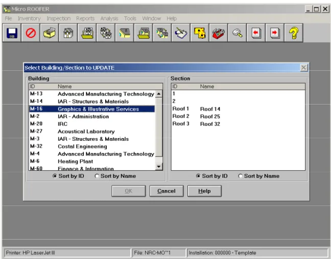
A selection form then appears, prompting the user to choose the building for which the three roof product objects are appended to its roof sections. In this scenario, the three roof product objects were added to “M-16-Graphics & Illustrative Services” building as illustrated in Fig. 13.
The three roof product objects, “Roof 14”, “Roof 25” and “Roof 32”, shown in Fig. 12, are then exported from the AMT as a data client component to MicroROOFER as a DS component within the Jigsaw system. The three exported roof product objects are treated as three distinct roof sections in the MicroROOFER application, as shown in Fig. 14.
The user can then record condition assessment data about the roof sections within the MicroROOFER application.
Figure 14: Addition of three new roof objects to existing roof section in MicroROOFER application
8.4 Importing / Exporting Data to Microsoft Project Application
After the condition assessment data has been input for “Roof 25” using MicroROOFER, and for the
purpose of composing this scenario, the roof condition index of “Roof 25” is 24% (out of a possible 100%). The Maintenance, Repair or Renewal (MRR) option that corresponds with this condition according to MicroROOFER’s set of MRR options is “Replace Roof”. The user can then add a set of tasks in the AMT application that need to be performed under the “Tasks” collection within the project hierarchy:
1. The user can enter the tasks within AMT as described below to create a schedule, or
2. The user specifying the set of tasks within Microsoft Project and then importing them into the AMT application.
Importing and exporting from and to Microsoft Project is facilitated by an adapter component
developed within Jigsaw to map the schema used in the AMT application to that of Microsoft Project. After creating the set of tasks, as described above, the user can examine each task to browse a list of product and asset objects that a task operates on, a list of predecessor tasks, and list of successor tasks. Fig. 9 illustrates an overview of the AMT’s user interface populated with data for a sample project file
“project 327”. The figure illustrates that the task object “Remove old thermal insulation board” operates on the “Roof 14” product object, which has been treated as an asset object with the name “Asset 1101-Roof”. The task object “Remove old roofing membrane felt” is the predecessor task, and the task “Remove old vapor barrier” is the successor task.
9. CONCLUSIONS
The paper presented a framework that aims at being a systematic and generic reference description to the practice of asset maintenance management. The framework serves to identify avenues throughout the practice of asset management where effective strategies and procedures (integration of data and knowledge through conceptual models) could be implemented to improve operations and sustain the capital investment in an asset through its life cycle.
The research also presented a general object-oriented domain model or schema for asset maintenance management. While the developed schema for asset maintenance management supports information exchange within the FM domain, it is capable of being re-used in other domains, hence supporting information exchange and demonstrating software interoperability among different domain areas. The paper finally presented the development of the AMT, a prototype integrated application that combines building product and process information; and is capable of importing and exporting IFC information. The prototype implements the developed process and data models in the context of distributed, model-based, integrated AEC/FM system architecture. The AMT prototype application was designed and implemented as a generic prototype application for the purpose of demonstrating software interoperability through the use of the internationally recognized IFC data standards to represent project information. The application is not limited to roof products only. Similar scenarios can be generated for demonstrating data exchange for diverse sets of building products.
10. ACKNOWLEDGEMENT
The authors would like to gratefully acknowledge support for this work by the National Research Council of Canada (NRCC), Public Works and Government Service of Canada (PWGSC); and the National Science and Engineering Research Council of Canada (NSERC).
11. REFERENCES
BLIS. (2001). Building Lifecycle Interoperable Software. <http://www.blis-project.org/> (November 5, 2001).
Eastman C. (1999). “Information Exchange Architectures for Building Models.” Proceedings of the 8th
International Conference on Durability of Building Components and Materials, Vancouver, Canada, May 30-June 3, Vol. 4, pp. 2139-2156.
Froese, T., Yu, K., Liston, K., and Fischer, M. (2000). “System Architecture for AEC Interoperability.” Proceedings of CIB-W78: International Conference on Construction Information Technology, Reykjavik, Iceland, June 28-30, G. Gudnason (Ed.), Icelandic Building Research Institute. Vol. 1, pp. 362-373.
Hassanain, M. A. (2002). “Integrated Systems for Maintenance Management.” PhD thesis, University of British Columbia, Dept. of Civ. Engrg., , Vancouver, Canada.
Hassanain, M. A., Froese, T. M., and Vanier, D. J. (2001). “Development of a Maintenance Management Model Based on IAI Standards.” Journal of Artificial Intelligence in Engineering, Elsevier Science, Vol. 15, No. 2, pp. 179-195.
International Alliance for Interoperability (IAI). (1999). “Specifications Development Guide.” Industry Foundation Classes – Release 2.0, March.
International Organization and Standardization (ISO-10303-11). (1994) Industrial Automation Systems and Integration – Product Data Representation and Exchange. Part 11: Description methods: The EXPRESS language reference manual, Geneva, Switzerland.
Jigsaw Distributed System (JDS). (2001). <http://construction.civil.ubc.ca/ jigsaw_technical/> (August 8, 2002).
Kyle, B. R, Vanier, D. J., Kosovac, B., and Froese, T. M. (2000). “Information Needs Towards Service Life Asset Management.” Proceedings of the 17th International Conference of the Committee on
Data for Science and Technology, Baveno, Italy, October 15-19.
Peters, F. and Meissner, U. (1995). “Object-Oriented Composition of a Framework for Integrative Facility Management.” Proceedings of CIB-W78/TG10: Modeling of Buildings Through Their Life Cycle, California, USA, August 21-23, pp. 111-118.
Vanier, D. J. (2001). “Why Industry Needs Asset Management Tools.” Journal of Computing in Civil Engineering, ASCE, Vol. 15, No. 1, pp. 35-43.