Publisher’s version / Version de l'éditeur:
2010 Annual Report Conference on Electrical Insulation and Dielectric
Phenomena, pp. 1-4, 2010-10-17
READ THESE TERMS AND CONDITIONS CAREFULLY BEFORE USING THIS WEBSITE. https://nrc-publications.canada.ca/eng/copyright
Vous avez des questions? Nous pouvons vous aider. Pour communiquer directement avec un auteur, consultez la première page de la revue dans laquelle son article a été publié afin de trouver ses coordonnées. Si vous n’arrivez pas à les repérer, communiquez avec nous à [email protected].
Questions? Contact the NRC Publications Archive team at
[email protected]. If you wish to email the authors directly, please see the first page of the publication for their contact information.
NRC Publications Archive
Archives des publications du CNRC
This publication could be one of several versions: author’s original, accepted manuscript or the publisher’s version. / La version de cette publication peut être l’une des suivantes : la version prépublication de l’auteur, la version acceptée du manuscrit ou la version de l’éditeur.
For the publisher’s version, please access the DOI link below./ Pour consulter la version de l’éditeur, utilisez le lien DOI ci-dessous.
https://doi.org/10.1109/CEIDP.2010.5724020
Access and use of this website and the material on it are subject to the Terms and Conditions set forth at
Space charge evolution in polypropylene containing synthetic and
natural organoclays
Abou Dakka, M.; Bulinski, A.; Bamji, S. S.
https://publications-cnrc.canada.ca/fra/droits
L’accès à ce site Web et l’utilisation de son contenu sont assujettis aux conditions présentées dans le site LISEZ CES CONDITIONS ATTENTIVEMENT AVANT D’UTILISER CE SITE WEB.
NRC Publications Record / Notice d'Archives des publications de CNRC:
https://nrc-publications.canada.ca/eng/view/object/?id=8281403f-271b-4161-85cf-a313a83ae22e https://publications-cnrc.canada.ca/fra/voir/objet/?id=8281403f-271b-4161-85cf-a313a83ae22eSpace Charge Evolution in Polypropylene Containing
Synthetic and Natural Organoclays
M. Abou Dakka, A. Bulinski and S.S. Bamji
Institute for National Measurement Standards National Research Council of Canada
Ottawa, Ontario, Canada, K1A 0R6
I. I
Nanodielectrics, especially those based on polymeric materials have received considerable attention over the last several years from the electrical power industry. It was preceded by a broad use of polymer nanocomposites (PNCs) in the auto, aerospace and chemical industries, where their superior mechanical, thermal and other properties over the base polymers found numerous applications. Since most of polymer nanocomposites are electrically insulating and the electrical power industry already uses large quantities of polymeric materials as electrical insulation, the efforts to determine whether the PNCs could also posses better dielectric properties and find wider application in the electrical industry area were inevitable. Some of the recently published data suggest that the PNCs do in fact have better electrical breakdown strength, surface and volume resistivity, space charge mitigation characteristics [1-3], resistance to partial discharges [4-8], etc.
It is generally agreed that the interfaces between nanoparticles and surrounding medium play major role in controlling the carrier transport through PNCs. Nanoparticles can change the depth and density of traps, which in turn change the density and mobility of space charge in the material. In other words, small quantities of nanoparticles could reduce charge injection and slow down the degradation of a PNC. However, this advantage could be lost by loading the polymer with excessive quantities of nanoparticles, which should normally be limited to the percolation threshold [9-12].
This communication summarizes effects of the concentration and the type of organoclay on the injection and the development of space charges in polypropylene-based PNCs. Two types of organoclay were used: Topy synthetic tetrasilisic mica
NTRODUCTION
Abstract-Fully synthetic tetrasilisic mica from Topy Co., Ltd. and Cloisite 20A powder of Wyoming natural montmorillonite clay from Southern Clay Products were used to manufacture poly-propylene-based nanocomposites with organoclay concentrations of up to 8-wt%. Both types of nanofiller reduce the amount of space charge accumulated under a dc field as compared with the base material without any nanoparticles but their concentrations have to be kept below ~4-wt% to achieve this effect. For the same particle concentration, nanocomposites containing natural clay, which has significantly smaller aspect ratio of the individual platelets than the synthetic clay, acquire less space charge than the nanocomposites containing fully synthetic clay.
®
mica and Cloisite 20A with natural montmorillonite from Wyoming. Nanocomposites were based on isotactic polypropylene and contained up to 8-wt% of clay. The goal of this work was to determine the optimum concentration of each type of the organoclay that would most effectively mitigate the development of space charges in the material under dc fields.
® II. EXPERIMENTAL A. Specimens ® ® ® An isotactic PP and two types of nano-filler: (1) the Topy synthetic tetrasilisic mica from Topy Co., Ltd. of Japan, pre-intercalated with di-methyl di-stearyl-ammonium chloride, and (2) Cloisite 20A natural montmorillonite clay from Wyoming, pre-intercalated with di-methyl di-hydrogenated tallow and manufactured by Southern Clay Products, were used to prepare PP-based nanocomposites with different contents of the clays. They are referred to in this paper as “PP+x% Topy” and “PP+y% C20A”, where x% indicates the percentage by weight content of the Topy organoclay and y% the percentage by weight content of the Cloisite 20A organoclay in PP, respectively. Unfilled polypropylene is marked throughout this paper as “PP-0%”. The Cloisite 20A particles had a narrower distribution of length and width than the Topy particles. The individual platelets aspect ratios were 6000 and 286 for Topy and Cloisite 20A, respectively.
The manufacture of nanocomposites involved three steps: (1) preparation of the Master Batch (MB), (2) dilution of MB, and (3) preparation of films.
The base PP material was melt compounded with a 1:1 mixture of two compatibilizers [PP grafted with maleic anhydride (PP-MA) from Eastman (Epolene 3015) and from Chemtura (Polybond 3150)], antioxidant Irganox B-225 (from Ciba) and one of the organoclays. The compounding was carried out at 200°C under a blanket of dry nitrogen in a twin-screw extruder (TSE; Leistritz 34 mm, L/D = 40; high shear intensity screw, speed: 200 rpm, T = 200°C; throughput: 5 kg/h). The resulting composition for Topy-based MB was: 75.8-wt% PP + 0.2-wt% antioxidant + 16-wt% compatibilizers + 8-wt% of clay, and for Cloisite-based MB: 81.8-wt% PP + 0.2-wt% antioxidant
®
£ £
Step 1. Preparation of the Master Batch (MB)
+ 12-wt% compatilizer + 6-12-wt% of clay.
2010 Annual Report Conference on Electrical Insulation and Dielectric Phenomena
Step 2. Dilution of MB
Step 3. Preparation of films
Samples containing 0, 1, 2, 4 and 8-wt% of Topy and 0, 2 and 6-wt% of Cloisite 20A were prepared. To ascertain the same compounding history of the samples all samples were extruded at 180°C under a blanket of dry nitrogen, using the same TSE with the same processing parameters as used for both MBs. Thus, PP + antioxidant were extruded twice. The MBs obtained in Step 1 were re-extruded and the other compositions were prepared by first dry-blending pre-extruded PP with each MB at an appropriate ratio and then re-extruding the blend. The clay dispersion parameters for the Topy and Cloisite 20A-based samples were: (1) the interlayer spacing d : 3.45 for Topy and 2.8 ± 0.2 nm for Cloisite , (2) the number of platelets in the residual stacks N: 2.64 for Topy and 3.1 ± 0.2 for Cloisite , and (3) the degree of exfoliation EX: 88% for Topy and 50% for Cloisite .
The pelletized dried compositions obtained in step 2 were film blown at T = 180°C to 230°C into films with an approx. thickness of 135 ± 7 µm. Subsequently, the films were rolled twice at 115°C between 3-rolls in a Metaplast calender, to obtain the final samples for testing.
All specimens were manufactured by the Industrial Materials Institute of NRC under the collaborative project to develop nanocomposite insulation for high voltage capacitor applica-tions. PP film capacitors constitute a significant share of a $2.8 billion USD market for polymer capacitors [13]. Specimens with Cloisite 20A have also been used in a project within the VAMAS Technical Working Area 33 (TWA-33) concerned with the development of test methods for chemical, morphological, mechanical and electrical characterization techniques for polymer nanocomposites.
VAMAS is an international organization, which supports world trade in products that depend on advanced materials technologies. It initiates and co-ordinates collaborative projects involving laboratories from different countries to provide the technical basis for harmonizing measurement techniques, testing procedures, specifications, and standards [14].
The specimens were subjected to a -25 kV/mm dc field at room temperature in air for up to 6 weeks. To ensure a good contact between the specimen and the electrodes a thin layer of silicon oil was applied on each side of the sample. A 0.2 mm thick and 30 mm in diameter semicon disk was inserted between the specimen and the upper brass electrode during the aging.
The measurements were performed using the Five Labs PEA measurement system having a resolution of ~17 µm and Tektronix 7404, 4 GHz, 20 GS/s digital oscilloscope.
After a predetermined time of aging a specimen was removed from aging and assembled in the PEA cell. The space charge distribution was measured with the sample subjected to a 4 kV/mm dc field. After the PEA measurements the specimen was returned to the aging setup and aged for the subsequent period of time. The space charge and the internal electric field
001
~
B. Aging Condition
C. Space Charge Measurements
® ® ® ® ® ® 20A 20A 20A
distributions were calculated using the Five Labs’ software.
III. RESULTS AND DISCUSSION
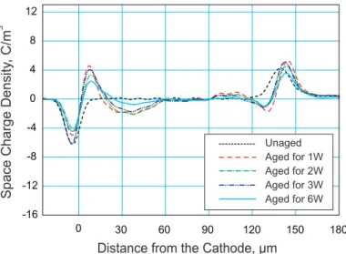
Fig. 1 shows the space charge evolution in the base material.
0 30 60 90 120 150 180 -16 -12 -8 -4 0 4 8 12 Unaged Aged for 1W Aged for 2W Aged for 3W Aged for 6W
Distance from the Cathode, µm
Space Charge Density
, C/m
3
Fig. 1. Space charge distributions in the base isotactic PP versus aging time at -25 kV/mm, dc.
Even after one week (1W) of exposure to -25 kV/mm, dc, caused the injection of homocharges from both electrodes. The amplitude of their peaks increased with aging time and the charges moved towards the centre of the sample.
Adding natural clay, at a 2-wt% concentration, changes significantly the profile and the quantity of the space charge. This is illustrated in Fig. 2. The overall quantity of charge in the PP-2% C20A sample is less than half of that in the base material and there is a clear suppression of charges in the centre of the sample. It was observed in [15] that the wider the central zone that contains no-charge or weak charges, the longer is the life time of the specimen subjected to a dc field.
Fig. 2.Space charge distributions in the PP-2% C20A versus aging time at a -25 kV/mm, dc. 0 30 60 90 120 150 180 -16 -12 -8 -4 0 4 8 12
Space Charge Density
, C/m
3
Distance from the Cathode, µm
Unaged Aged for 1W Aged for 2W Aged for 3W Aged for 6W
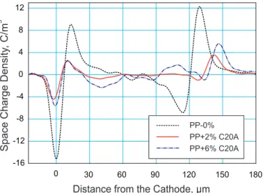
Fig. 3 shows the effect of natural clay concentration on space charges after 6 weeks of aging.
Both nanocomposites contain significantly less space charge than the base polymer. However, the lower, 2-wt% concentration of the clay is more effective in reducing the amount of space charge in the material than the higher concentration (6-wt%). Similar effect was reported for the synthetic organoclay in [16].
A relatively small amount of charge in nanocomposites as compared with the base polymer is caused probably by the interfaces between the nanoparticles and the polymer. The nanoparticles form a large interface area with the polymer. The charges injected into the material could be trapped at these interfaces and their mobility decreased. This in turn would prevent further charge injection into the material. However, as the concentration of nanoparticles increases the interaction zones, or Gouy-Chapman-Stern layers [4, 17] that develop around nanoparticles, can overlap. Under a dc field these double layers would provide a path for ion migration and lead to increased charge penetration.
The amount of space charge and the resulting electric field are significantly higher for the synthetic organoclay than for the natural one. Since the aspect ratio of the individual pletelets for the Topy nanoparticles is much larger than that for the Cloisite C20A ( ), there is a higher probability that for the same concentration, the Topy nanoparticles overlap more in the nanocomposite than the Cloisite C20A nanoparticles and hence provide more efficient pathway for charge transport.
Fig. 6 summarizes the results for polypropylene containing synthetic organoclay. PNCs with the nanoparticle concentrations of up to 8-wt% were tested. £6000 versus£286, respectively ® ® 0 30 60 90 120 150 180 -16 -12 -8 -4 0 4 8 12
Space Charge Density
, C/m 3 PP-0% PP+2% C20A PP+6% C20A PP-0% PP+2% C20A PP+6% C20A
Distance from the Cathode, µm
This is further substantiated by Figures 4 and 5, which show the space charge and electric field distributions after 6 weeks of aging in nanocomposites containing natural and synthetic organoclays at a 2-wt% concentration. 0 30 60 90 120 150 180 -16 -12 -8 -4 0 4 8 12 PP+2% C20A PP+2% Topy
Space Charge Density
, C/m
3
Distance from the Cathode, µm
Fig. 4. The effect of the type of organoclay on the space charge distributions after 6 weeks of aging. Both nanocomposites had the same, 2-wt%
particle concentration. 0 20 40 60 80 100 120 140 160 180 -8 -6 -4 -2 0
Electric Stress, kV/mm PP+2% C20A
PP+2% Topy
Distance from the Cathode, µm
Fig. 5. The effect of organoclay type on the internal electric field distributions after 6 weeks of aging.
0 30 60 90 120 150 180 -16 -12 -8 -4 0 4 8 12
Space Charge Density
, C/m 3 PP-0% PP+2% Topy PP+4% Topy PP+8% Topy
Distance from the Cathode, µm
Fig. 6. The effect of the synthetic nanoparticle concentration on the space charge distributions after 6 weeks of aging at -25 kV/mm, dc. Fig. 3. The effect of nanoparticle concentration on the space charge
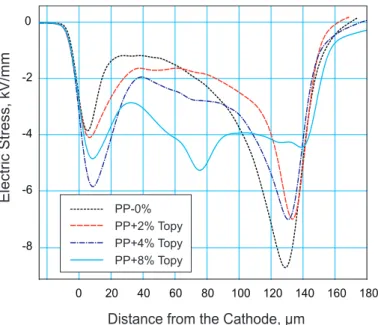
As in the case of natural clay (Fig. 3) the least amount of space charge after 6 weeks of aging was recorded in the material with a 2-wt% nanoparticle concentration, especially in the central region of the sample. For a sample with 8-wt% particle concentration, charges of the opposite polarity were clearly present in the center, which increased the intensity of electric stress in that region. This stress is considerably higher than in the base PP, without any nanoparticles (Fig. 7).
0 20 40 60 80 100 120 140 160 180 -8 -6 -4 -2 0 Electric Stress, kV/mm
Distance from the Cathode, µm
PP-0% PP+2% Topy PP+4% Topy PP+8% Topy
Fig. 7.Effect of synthetic particle concentration on electric field distributions after 6 weeks of aging at -25 kV/mm, dc.
The observed effect, which from the space charge accumulation point of view defies any benefits offered by the presence of a nano-clay, is believed to be caused by too high a concentration of nanoparticles in the material, which enhances overlapping of the diffuse double layer charge clouds around nanoparticles and promotes movement of space charges. In order to obtain and maintain space charge suppression by using nano-clay in polymers one needs to use concentrations below the percolation threshold [12] and ensure uniform distribution of nano-particles throughout polymer matrix.
IV. C
The evolution of a space charge with time of aging under a dc field in the polypropylene-based nanocomposites containing natural and synthetic organoclays was investigated.
Both types of nanocomposites exhibited less charge injection and reduced amount of space charge than the base polymer but only if the nanoparticle concentration was ~2 to 4-wt%, i.e. below the percolation threshold.
For the same nanoparticle concentration and the same time of aging, the samples with natural clay had less space charge than the samples containing synthetic clay. This is believed to be
ONCLUSIONS
caused by significantly larger aspect ratio of the individual platelets of the synthetic organoclay, which increases overlapping of the diffused double layer charge clouds that are around the nanoparticles and promotes charge transport.
A
The authors wish to thank Dr. L. A. Utracki of the Industrial Materials Institute of NRC Canada for providing nanocomposite specimens for this work. They also would like to thank Mrs. Y. Chen of the Institute for National Measurement Standards, NRC, for her technical support.
CKNOWLEGEMENTS
REFERENCES
[1] M. Roy, J.K. Nelson, R.K. MacCrone and L.S. Schadler, “Candidate Mechanisms Controlling the Electrical Characteristics of Silica/XLPE Nanodielectrics”, J. Mater. Sci. Vol. 42, pp. 3789-3799, 2007.
[2] C.D. Green, A.S. Vaughan, G.R. Mitchell and T. Liu, “Structure Property Relationship in Polyethylene/ Montmorillonite Nanodielectrics”, IEEE Trans. Dielectrics Elect. Insul., Vol. 15, pp. 134-143, 2008.
[3] T. Tanaka, G.C. Montanari, and R. Mülhaupt, “Polymer Nanocomposites as Dielectrics and Electrical Insulation – Perspectives for Processing Technologies, Material Characterization and Future Applications”, IEEE Trans. Dielectrics Elect. Insul., Vol. 11, pp. 763-784, 2004.
[4] J.K. Nelson, Y. Hu, “Nanocomposite Dielectrics – Properties and Implications”, J. Phys. D: Appl. Phys., Vol. 38, pp. 213-222, 2005. [5] N. Fuze, Y. Ohki, M. Kozako and T. Tanaka, “Possible Mechanisms of
Superior Resistance of Polyamide Nanocomposites to Partial Discharges and Plasmas”, IEEE Trans. Dielectrics Elect. Insul., Vol. 15, pp. 161-169, 2008.
[6] M. Takala, M. Karttunen, P. Salovaara, S. Kortet, K. Kannus and T. Kalliohaka, “Dielectric Properties of Nanostructured Polypropylene-Polyhedral Oligomeric Silsesquioxane Compounds”, IEEE Trans. Dielectrics Elect. Insul., Vol. 15, pp. 40-51, 2008.
[7] T. Tanaka, “Interface Properties and Surface Erosion Resistance”, in “Dielectric Polymer Nanocomposites”, Springer Science and Business Media, LLC 2010, ISBN 978-1-4419-1590-0, K. Nelson Editor, pp. 229-258.
[8] A. Bulinski, S. Bamji and M. Abou Dakka, “Dielectric Properties of Polypropylene Containing Synthetic and Natural Organoclays”, Proc. IEEE ISEI'2010, San Diego, CA, 6-9 June 2010
[9] T.J Lewis, “Interfaces: Nanometric Dielectrics”, J. Phys. D: Appl. Phys., Vol 38, pp-202-2012, 2005.
[10] M. Frèchette, and C.W. Reed, “The Role of Molecular Dielectrics in Shaping the Interface of Polymer Nanodielectrics”, Annual Report CEIDP'2007, Vancouver, BC, Canada, October 14–17, pp 279-285, 2007. [11] M.G. Danikas and T. Tanaka, “Nanocomposites – A Review of Electrical
Treeing and Breakdown”, IEEE Electr. Insul. Magazine, Vol. 25, No. 4, pp-19-25, 2009.
[12] E.J. Garboczi, K.A. Snyder, J.F. Douglas, and M.F. Thorpe, “Geometrical Percolation Threshold of Overlapping Ellipsoids”, Phys. Rev. E, Vol. 52, No. 1, pp -819-828, 1995.
[13] Qi Tan, P. Irwin and Y. Cao, “Advances Dielectrics for Capacitors”, IEEJ Trans. FM, Vol. 126, No. 11, pp. 1153-1159, 2006.
[15] M. Abou-Dakka, Alexander Bulinski and Soli Bamji, “Space charge Development and breakdown in XLPE under DC field”, IEEE Trans. Dielectrics Elect. Insul.,Vol. 11, pp. 41-49, 2004.
[16] S. S. Bamji, A. Bulinski, M. Abou Dakka and D. McIntyre, "Space Charge in Polypropylene Containing Synthetic Nanoparticles", Annual Report, CEIDP'2009, Virginia Beach, VA, USA, 18-21 Oct. 2009.
[17] J. Lewis, “Interfaces are the Dominant Feature of Dielectrics at the Nanometric Level”, IEEE Trans. Dielectrics Elect. Insul., Vol. 11, pp. 739-753, 2004.