Publisher’s version / Version de l'éditeur:
Metallurgical and Materials Transactions A, 38, 6, pp. 1337-1342, 2007-06-01
READ THESE TERMS AND CONDITIONS CAREFULLY BEFORE USING THIS WEBSITE.
https://nrc-publications.canada.ca/eng/copyright
Vous avez des questions? Nous pouvons vous aider. Pour communiquer directement avec un auteur, consultez la première page de la revue dans laquelle son article a été publié afin de trouver ses coordonnées. Si vous n’arrivez pas à les repérer, communiquez avec nous à PublicationsArchive-ArchivesPublications@nrc-cnrc.gc.ca.
Questions? Contact the NRC Publications Archive team at
PublicationsArchive-ArchivesPublications@nrc-cnrc.gc.ca. If you wish to email the authors directly, please see the first page of the publication for their contact information.
NRC Publications Archive
Archives des publications du CNRC
This publication could be one of several versions: author’s original, accepted manuscript or the publisher’s version. / La version de cette publication peut être l’une des suivantes : la version prépublication de l’auteur, la version acceptée du manuscrit ou la version de l’éditeur.
For the publisher’s version, please access the DOI link below./ Pour consulter la version de l’éditeur, utilisez le lien DOI ci-dessous.
https://doi.org/10.1007/s11661-007-9187-5
Access and use of this website and the material on it are subject to the Terms and Conditions set forth at
Machinability of green powder metallurgy components : Part II. Sintered
properties of components machined in green state
Robert-Perron, Etienne; Blais, Carl; Pelletier, Sylvain; Thomas, Yannig
https://publications-cnrc.canada.ca/fra/droits
L’accès à ce site Web et l’utilisation de son contenu sont assujettis aux conditions présentées dans le site LISEZ CES CONDITIONS ATTENTIVEMENT AVANT D’UTILISER CE SITE WEB.
NRC Publications Record / Notice d'Archives des publications de CNRC:
https://nrc-publications.canada.ca/eng/view/object/?id=f96a8d1d-d36f-48ed-ae19-347070e7a7d8 https://publications-cnrc.canada.ca/fra/voir/objet/?id=f96a8d1d-d36f-48ed-ae19-347070e7a7d8Machinability of Green Powder Metallurgy Components: Part II.
Sintered Properties of Components Machined in Green State
ETIENNE ROBERT-PERRON, CARL BLAIS, SYLVAIN PELLETIER, and YANNIG THOMAS
The green machining process is virtually a must if the powder metallurgy (PM) industries are to solve the lower machining performances associated with PM components. This process is known for lowering the rate of tool wear. Recent improvements in binder/lubricant technologies have led to high-green-strength systems that enable green machining. Combined with the optimized cutting parameters determined in Part I of the study, the green machining of PM components seems to be a viable process for fabricating high performance parts on large scale and complete other shaping processes. This second part of our study presents a comparison between the machining behaviors and the sintered properties of components machined prior to or after sintering. The results show that the radial crush strength measured on rings machined in their green state is equal to that of parts machined after sintering.
DOI: 10.1007/s11661-007-9187-5
ÓThe Minerals, Metals & Materials Society and ASM International 2007
I. INTRODUCTION
P
OWDERmetallurgy (PM) is a shaping process that allows the fabrication of relatively complex components at high production rates.[1] The PM process competes with other shaping processes, such as precision casting, precision forging, and the machining of wrought metals. However, incorporating features such as threads, holes perpendicular to the pressing axis, and undercuts is very difficult to do and must be added to the sintered components via machining operations. Moreover, the machining of PM components is also done to maintain the geometrical conformance of sintered products.[2] According to a survey of the PM industry, approxi-mately 30 pct of all PM components produced in North America require some machining operation after sinter-ing.[3]Moreover, it is estimated that about 40 to 50 pct of all ferrous and steel PM parts made in Europe undergo some machining.[2]Unfortunately, the machin-ing performances of PM components differ from those of wrought steel components that present the same microstructure. The reasons for the inferior machinabil-ity behavior of PM components come from the substantial volume of residual porosities (10 to 15 pct) that affect the interaction between the cutting tool and the work material.[4,5,6]The decreased tool life and the higher cost associated with the machining of PM components could counter-balance the advantages offered by the PM process. Thus,
to remain competitive with other shaping processes, the PM industry has to solve the machinability issue inherent to PM components, to enhance precision and extend the shape complexity of the components it produces.[1]As mentioned in Part I of this study, successful efforts have been undertaken to include machinability enhancers (MnS, MoS2) in PM steels, for improved machining
behaviors.[7,8,9] Unfortunately, these additives tend to decrease the sintered properties, especially toughness and fatigue resistance.[1,10]In recent years, a new approach to circumventing the mediocre machining performances of PM steels has been considered: green machining. According to Salak,[2]‘‘Green machining is virtually a must for PM components that are sinter hardened.’’ In green machining, the cutting forces and the temperature at the tool/chip interface are kept to a minimum, due to the lack of strong interparticles bonding. Moreover, the hard phases that lower the cutting tool life have not been formed at this stage of the process, because phase transformation (austenite to martensite/bainite) usually occurs during the cooling stage of the sintering process. As for sintered components, the cutting conditions are of crucial importance when machining green PM parts. However, the cutting parameters used for producing high-quality components via green machining signifi-cantly differ from those used for the machining of sintered products. It is has been shown that the surface speed can be maximized for productivity purpose, because it mar-ginally affects the quality of the outcome, based on such criteria as the surface finish and the width of breakouts.[11] Also, it is believed that the feed rate must be kept to a value of 0.0254 mm/r (or even lower), for preventing the pullout of particles near the edges and for optimizing the surface finish.[11–16] However, based on the conclusions presented in Part I, this statement is only partly true. A feed rate of 0.0254 mm/r would be a good selection for machining only a few parts, but if the number of components to machine becomes important, a feed rate such as this is not advisable. Indeed, as presented in the
ETIENNE ROBERT-PERRON, Postdoctoral Candidate, and CARL BLAIS, Professor, are with the Department of Mining, Metallur-gical and Materials Engineering, Universite´ Laval, Quebec City, QC, Canada G1K 7P4. Contact e-mail: etienne.robert-perron.1@ulaval.ca SYLVAIN PELLETIER, Powder Metallurgy Group Leader, and YANNIG THOMAS, Research Officer, are with the Powder Forming Research Group, Industrial Materials Institute–National Research Coun-cil, Boucherville, QC, Canada J4B 6Y4.
Manuscript submitted on October 11, 2006. Article published online June 26, 2007.
first part of this study, a feed rate of 0.0254 mm/r would lead to premature wear at the cutting edge of the tool and would drastically affect the quality of the outcome.
Tool wear is usually considered as a negligible factor in green machining. Nonetheless, tool wear exists in green machining and it has a strong effect on the machinability of green PM components when it is uncontrolled. In Part I of this study,[17] it has been shown that a feed rate of 0.0635 mm/r would minimize the effect of the tool wear when facing green PM components. Also, the surface speed suggested for preventing tool wear is 366 m/min. The tool holder and the cutting tool also influence the facing of green PM components. Tool holder SCLCR102 and cutting tool CPMT060204FW (Kennametal Ltd., Ontario, Canada) (or their equivalents) are suggested for use in decreasing the degradation of the quality related to tool wear. Under these conditions, it seems that green machining offers an alternative route for producing high-performance PM components on a large scale. However, green machining still appears to be a marginal process, due to a lack of knowledge concerning the sintered properties of such components. The objective of the second part of this study was to compare green and sintered PM steel with respect to both their machining performances and their mechanical properties. This was achieved by characterizing the rate of tool wear for both series of components. First, the variation of the average width of breakouts and the surface finish were charac-terized as a function of the rate of tool wear during green machining experiments. Second, the radial crush strength of the sintered components machined in their green state was measured and compared to that of parts machined conventionally (after sintering).
II. EXPERIMENTAL PROCEDURE
A. Material Investigated
A powder system was produced based on the Que-bec Metal Powders ATOMET* 1001 (Fe-0.2 wt pct
Mn-0.07 wt pct Ni-0.05 wt pct Cr), to which was added 1.8 wt pct Cu and 0.65 wt pct graphite. The latter premix follows the denomination FC-0205, based on the MPIF Standard 35.[18]Lubrication was done using 0.65 wt pct of a proprietary binder/lubricant (FLOMET HGS**)
specifically adapted for high green strength. This mix was pressed into rings (7.20-cm o.d., 3.40-cm i.d., and 2.30 cm in height) to a green density of 7.00 g/cm3.
A first series of samples was obtained by curing rings in air at 190 °C for 1 hour, to increase their green
strength to 45 MPa and their machinability in terms of surface finish and edge integrity. This series was used for the characterization of the machining performances of the green PM components. After machining, these samples were sintered with initial rings (unmachined components) in a belt furnace, at 1120 °C for 25 minutes in a 90 pct N2-10 pct H2atmosphere.
B. Machining Operations
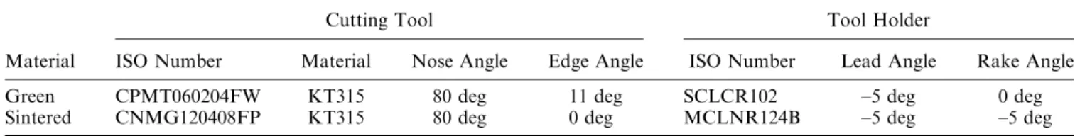
The first series of samples was machined in their green state (prior to sintering). Three machining operations were performed on rings: the external turning, the internal turning, and the facing of both sides. The final dimensions are as follows: o.d. = 7.10 cm, i.d. = 3.50 cm, and height = 1.15 cm. A special fixture was used to hold the green PM components during the external turning. The samples had a hole in the middle and they were fixed to a wrought steel bar using a screw and a tight-fitting bushing. The bar was then placed in the chuck of the lathe (Figure 1(a)). For the internal turning and the facing, components were held directly by the jaws of the chuck, as shown in Figure 1(b). The second series of samples was obtained by machining rings after sintering to the dimensions of those machined in their green state (considering the dimensional change). The cutting tool and the tool holder used for the machining of the green PM specimens were chosen following the conclusions presented in Part I.[17]Table I presents the tools used for the machining of both series of samples.[19]Different tools were used for the machin-ing of green and sintered components, to take into account the different machining behavior of the two series of samples. Therefore, optimum cutting parame-ters were used to machine the green and sintered specimens, which implies that these cutting parameters differed from one series to the other. Table II presents the cutting parameters used for the machining of green specimens (these were optimized in Part I) as well as the cutting parameters used for the machining of sintered parts. The cutting parameters used for the machining of the sintered components are based on the recommen-dations found in the literature.[20,21]The productivity or the rate of material removal for the machining of both series of samples is presented in Table II. It is seen that there is an important increase in productivity with the machining of the components in their green state, due to the usage of a high surface speed.
C. Characterization of the Machining Performances
Tool wear was measured using optical microscopy. Flank wear and crater wear are the two most important forms of wear taking place on a cutting tool. Flank wear is the only acceptable form of tool wear, however, because it can be predicted. Moreover, the amount of flank wear is the criterion generally used in the shop for deciding whether an insert needs to be indexed.[19]Flank wear was characterized using a robust image analysis routine. The details of this method are explained well by Blais and L’Espe´rance.[20]Flank wear was characterized at every 150 cm3of removed material for the series that
*ATOMET is a trademark of Quebec Metal Powders Ltd., Quebec, Canada.
**FLOMET is a trademark of Quebec Metal Powders Ltd., Quebec, Canada.
was green machined, and at every 35 cm3for the series that was machined after sintering. The average width of the breakouts and the surface finish was also measured on the components that were machined in their green state, at each 150 cm3of removed material. The average width of the breakouts was measured in the area near the outlet edge, which is defined as the last edge seen by the cutting tool. (It is the edge near the inside diameter, because the cutting tool starts from the outside diameter of rings.) The image analysis technique developed for the characterization of the width of the breakouts was detailed in Part I.[17] The surface finish was measured using a stylus profilometer.[22] Two different measures were analyzed: Ra, which is the arithmetic mean of the
absolute values of the profile deviation from the mean line, and Rz, which is the sum of the mean height of the
five highest profile peaks and the mean depth of the five deepest profile valleys, as measured from a line parallel to the mean line.
D. Sintered Properties
The dimensional change of samples machined in their green state was measured after sintering and compared to that of unmachined rings. The dimensional change from the green size was measured on the outside diameter of the rings. The apparent hardness was measured on both series of samples. Radial crush tests
were performed on the sintered rings that were machined; the tests were performed either in the green state of the samples or after sintering them, following the Metal Powder Industries Federation (MPIF) stan-dard 55.[23] For samples machined in their green state, the crush strength was measured and averaged using three different specimens at increments of 350 cm3 of removed; for samples machined after sintering, all samples were tested.
III. RESULTS AND DISCUSSION
A. Characterization of Tool Wear
Figure 2 presents the rate of tool wear characterized during the machining of the two series of samples. It is seen that the machining of green PM components significantly lowers the rate of the tool wear. This is due to the low strength of green samples as compared to that of sintered parts. Figure 3(a) presents the edge of the cutting tool after the machining of green samples (removed material: 3500 cm3), while Figure 3(b) shows the cutting tool after the machining of sintered parts (removed material: 450 cm3). The wear characterized after the machining of the green PM samples is smooth and homogeneous, while deep notches are visible at the tip of the tool after the machining of sintered parts.
B. Characterization of the Average Width of Breakouts
It is seen in Figure 4 that the average width of breakouts increases linearly as the test progressed (correlation coefficient: R2= 0.91) This behavior is related to the rate of the tool wear. The latter increases as the quantity of removed material increases, which leads to a decreased sharpness of the cutting edge. When
Fig. 1—(a) Fixture used for external turning: (1) the steel bar fixed in the chuck of the lathe to hold the sample, (2) the sample to be machined, and (3) the tightening screw used to fix the sample on the steel bar; and (b) the components held in the jaws of the chuck, for the internal turn-ing and the facturn-ing.
Table I. Cutting Tool/Tool Holder Specifications
Material
Cutting Tool Tool Holder
ISO Number Material Nose Angle Edge Angle ISO Number Lead Angle Rake Angle Green CPMT060204FW KT315 80 deg 11 deg SCLCR102 –5 deg 0 deg Sintered CNMG120408FP KT315 80 deg 0 deg MCLNR124B –5 deg –5 deg
Table II. Cutting Parameters Selected
Material Surface Speed (m/min) Feed Rate (mm/r) Depth of Cut (mm) Productivity (cm3/min) Green 366 0.0635 0.25 5.8 Sintered 120 0.1016 0.25 3.1
machining green PM components with a worn cutting tool, the particles near the outlet edge are not ade-quately cut but mostly pushed out, which increases the width of the breakouts. Figure 5 presents the outlet edge characterized after the machining of 35 cm3 (Figure 5(a)), 1100 cm3 (Figure 5(b)), and 3500 cm3 (Figure 5(c)), respectively.
C. Characterization of the Surface Finish
The decreased sharpness of the cutting tool, after machining several parts, deteriorates the surface finish, as presented in Figure 6. At the beginning of the test, the cutting tool sheared the particles with minimal smearing of the latter, as shown in Figure 7(a) (35 cm3). In Figure 7(a), pores are opened due to the very low deformation of particles prior to shearing. As the sharpness of the cutting tool decreases, the particles tend to deform plastically before shearing. This explains the smearing of particles that partly closes the porosities in Figure 7(b) (1100 cm3). Figure 7(c) presents the surface after the passage of the cutting tool at the end of the test (3500 cm3). Marks left by the worn cutting tool are also visible in Figure 7(c).
D. Characterization of the Sintered Properties
The dimensional change after sintering of samples machined in their green state was characterized. The
results indicate that the dimensional change of compo-nents machined in their green state is very stable and does not vary with the rate of tool wear (average: 0.33 pct, standard deviation: 0.02 pct). Moreover, the dimensional change of these samples is identical to that of unmachined components.
Mechanical properties of components machined in their green state and components machined after sin-tering has been characterized using radial crush tests. Figure 8 presents the radial crush strength for both series as a function of the quantity of the removed material. It is seen that the radial crush strength of components machined in their green state does not vary significantly with the quantity of removed material (or with the rate of tool wear). The overall average radial crush strength for samples machined in their green state is 735 MPa, which can be compared to 761 MPa, when the components are machined after sintering. The slight difference (3 pct) between the two sets of results is not significant, because the standard deviations are 78 and 30 MPa, for the parts machined in their green state and parts machined after sintering, respectively. The PM rings machined in green state were held directly in the jaws of the chuck during internal turning and facing. Therefore, based on the sintered properties measured, the holding of the green sample during machining did not initiate crack or microcrack formation, which would have led to a decreased sintered strength. The apparent hardness measured on samples from both series is identical: 75 Hardness Rockwell B (HRB).
. 0 00 . 0 01 . 0 02 . 0 03 . 0 04 . 0 05 0 500 1000 1500 2000 2500 3000 3500 4000 Greenparts Si tn reedparts m c ( l a i r e t a m d e v o m e r f o y t i t n a u Q 3) Tool wear (mm)
Fig. 2—Comparison of the cutting tool wear during the machining of the green and the sintered PM steel.
y = .008x+120.42 R2= .0 19 0 0 0 1 0 0 2 0 0 3 0 0 4 0 0 5 0 500 1000 1500 2000 2500 3000 3500 4000 m c ( l a i r e t a m d e v o m e r f o y t i t n a u Q 3) Width of breakouts (µm)
Fig. 4—Variation in the average width of the breakouts during the machining of the green PM components.
Fig. 3—Cutting edge at the end of the test (characterized using a scanning electron microscope (SEM)): (a) the cutting tool used for the machin-ing of the green PM components (removed material: 3500 cm3) and (b) the cutting tool used for the machining of the sintered parts (removed material: 450 cm3).
IV. CONCLUSIONS
The optimum cutting conditions for machining green PM components, as characterized in Part I of this study,[17] were used to fabricate fully-green-machined rings on a large scale. Both the quality of the outcome
and the sintered properties have been characterized as a function of tool wear. The main findings of our research are the following.
1. The rate of tool wear is significantly lower when machining green PM components as compared to sintered products.
2. As tool wear increases in green machining, it affects the quality of the components. A worn cutting tool presents a decreased sharpness at the cutting edge, which leads to particle deformation prior to shear-ing. The average width of breakouts increases as tool wear increases, because the tool tends to push the particles out of the outlet edge as it leaves the components. A worn cutting tool degrades the sur-face finish, because smearing or pullout occurs. 3. The radial crush strength of PM rings machined in
their green state is similar to that of components machined conventionally (after sintering). More-over, the dimensional change is unaffected by the green machining process.
4. Clamping the green PM rings directly into the jaws of the lathe did not initiate the formation of cracks or microcracks.
Fig. 5—Typical average width of breakouts characterized in the SEM near the outlet edge (inside the diameter of rings), after the machining of green PM components: (a) 35 cm3, (b) 1100 cm3, and (c) 3500 cm3.
0 . 0 0 . 2 0 . 4 0 . 6 0 . 8 0 500 1000 1500 2000 2500 3000 3500 4000 v o m e r f o y t i t n a u Q edmaterial(cm3) Ra (µm) 0 1 0 2 0 3 0 4 0 5 0 5 00 1000 1500 2000 2500 3000 3500 4000 v o m e r f o y t i t n a u Q edmaterial(cm3) Rz (µm) (a) (b)
Fig. 6—Variation of surface finishes during the machining of the green PM components: (a) Raand (b) Rz.
Fig. 7—Typical surface characterized in the SEM after the machining of (a) 35 cm3, (b) 1100 cm3, and (c) 3500 cm3.
0 0 2 0 0 3 0 0 4 0 0 5 0 0 6 0 0 7 0 0 8 0 0 9 0 3 0 5 0 7 0 9 0 1 1 0 3 1 Machinedin rgeenst ta e Machinedafter si tn re ing
0 0 0 1 0 2000 3000 4000 m c ( l a i r e t a m d e v o m e R 3),machinedingreenstate
Crush Strength (MPa)
(Kpsi) 0 0 1 0 200 300 400 500 m c ( l a i r e t a m d e v o m e R 3),machinedaftersintering
Fig. 8—Crush strength of the sintered PM components machined in their green state or after sintering, as a function of the quantity of removed material.
Such conclusions stem from the identical radial crush strength of components machined prior to or after sintering. Therefore, high-strength components can be manufactured on a large scale using the green machining process.
ACKNOWLEDGMENTS
The authors thank Dr. Sylvain St-Laurent, Quebec Metal Powders, for the fruitful discussions, and Denis Christopherson and Julie Campbell-Tremblay, Federal-Mogul Sintered Products, for sintering the rings.
REFERENCES
1. R.M. German: Powder Metallurgy and Particulate Processing, Metal Powder Industries Federation, Princeton, NJ, 2005, pp. 335–68.
2. A. Salak, M. Selecka, and H. Danninger: Machinability of Powder Metallurgy Steels, Cambridge International Science Publishing, Cambridge, United Kingdom, 2005, pp. 1–4, 393–98.
3. D.S. Madan: Adv. Powder Metall. Part. Mater., 1995, Part 8, pp. 55–67.
4. R.J. Causton: Adv. Powder Metall. Part. Mater., 1995, Part 8, pp. 149–70.
5. J.S. Agapiou and M.F. DeVeries: Int. J. Powder. Metall., 1988, vol. 24(1), pp. 47–57.
6. J.L. Seefelt, D.W. Smith, and P. Machmeier: Adv. Powder Metall. Part. Mater., 1990, vol. 1, pp. 323–40.
7. C. Blais, G. L’Espe´rance, and I. Bourgeois: Powder Metall., 2001, vol. 44, pp. 67–76.
8. K.S. Chopra: Adv. Powder Metall. Part. Mater., 1988, pp. 361–79. 9. U. Engstro¨m: Powder Metall., 1983, vol. 26, pp. 137–44. 10. L. Jiang, K. Cui, and H. Ha¨nninen: J. Mater. Process. Technol.,
1996, vol. 58, pp. 160–65.
11. A. Benner and P. Beiss: Adv. Powder Metall. Part. Mater., 2001, Part 6, pp. 1–15.
12. A. Benner and P. Beiss: Euro PM2000 Conf. on Material and Processing Trends for PM Components in Transportation Proc., European Powder Metallurgy Association (EPMA), Vienna, 2000, pp. 101–09.
13. O. Andersson and A. Benner: Adv. Powder Metall. Part. Mater., 2001, Part 6, pp. 16–28.
14. M. Ramstedt, O. Andersson, H. Vidarsson, and B. Hu: Adv. Powder Metall. Part. Mater., 2001, Part 12, pp. 151–62. 15. O. Andersson and A. Benner: Adv. Powder Metall. Part. Mater.,
2001, Part 6, pp. 16–28.
16. E. Robert-Perron, C. Blais, Y. Thomas, S. Pelletier, and M. Dionne: Mater. Sci. Eng. A-Struct., 2005, vol. 402, pp. 325–34. 17. E. Robert-Perron, C. Blais, Y. Thomas, and S. Pelletier: Universite´
Laval, Que´bec, unpublished research, 2006.
18. Standard 35, Metal Powder Industries Federation, Princeton, NJ, 1998.
19. Kennametal: Lathe Tooling, catalogue 1010, Latrobe, PA, 2001, 358 pp.
20. C. Blais and G. L’Espe´rance: Powder Metall., 2002, vol. 45, pp. 39–47.
21. J. Campbell-Tremblay, C. Blais, G. L’Espe´rance, and P. Boilard: Adv. Powder Metall. Part. Mater., 2005, part 10, pp. 150–59. 22. Mitutoyo: Surface Finish Tester SJ-201P User’s Manual,
no. 99MBB079A, series no. 178.
23. Standard 55, Metal Powder Industries Federation, Princeton, NJ, 1998.