Publisher’s version / Version de l'éditeur:
Canadian Journal of Civil Engineering, 33, June 6, pp. 785-793, 2006-06-01
READ THESE TERMS AND CONDITIONS CAREFULLY BEFORE USING THIS WEBSITE.
https://nrc-publications.canada.ca/eng/copyright
Vous avez des questions? Nous pouvons vous aider. Pour communiquer directement avec un auteur, consultez la
première page de la revue dans laquelle son article a été publié afin de trouver ses coordonnées. Si vous n’arrivez pas à les repérer, communiquez avec nous à [email protected].
Questions? Contact the NRC Publications Archive team at
[email protected]. If you wish to email the authors directly, please see the first page of the publication for their contact information.
NRC Publications Archive
Archives des publications du CNRC
This publication could be one of several versions: author’s original, accepted manuscript or the publisher’s version. / La version de cette publication peut être l’une des suivantes : la version prépublication de l’auteur, la version acceptée du manuscrit ou la version de l’éditeur.
For the publisher’s version, please access the DOI link below./ Pour consulter la version de l’éditeur, utilisez le lien DOI ci-dessous.
https://doi.org/10.1139/L05-088
Access and use of this website and the material on it are subject to the Terms and Conditions set forth at
Corrosion characteristics and key electrochemical factors in patch repair
Zhang, J. Y.; Mailvaganam, N. P.
https://publications-cnrc.canada.ca/fra/droits
L’accès à ce site Web et l’utilisation de son contenu sont assujettis aux conditions présentées dans le site LISEZ CES CONDITIONS ATTENTIVEMENT AVANT D’UTILISER CE SITE WEB.
NRC Publications Record / Notice d'Archives des publications de CNRC:
https://nrc-publications.canada.ca/eng/view/object/?id=beba5564-c8dc-4fc9-879c-6289319fa552 https://publications-cnrc.canada.ca/fra/voir/objet/?id=beba5564-c8dc-4fc9-879c-6289319fa552
http://irc.nrc-cnrc.gc.ca
Cor rosion of c onc re t e re inforc e m e nt a nd
e le c t roche m ic a l fa c t ors in c onc re t e
pat ch re pa ir
N R C C - 4 7 6 5 4
Z h a n g , J . ; M a i l v a g a n a m , N . P .
A version of this document is published in / Une version de ce document se trouve dans: Canadian Journal of Civil Engineering, v. 33, no. 6, June 2006, pp. 785-793 doi:10.1139/L05-088
Corrosion of Concrete Reinforcement and Electrochemical Factors in Concrete Patch
Repair
Jieying Zhang and Noël P. Mailvaganam Dr. Jieying Zhang, Research Associate
Urban Infrastructure
Institute for Research in Concrete
National Research Council, Ottawa, Canada, K1A0R6
Noël P. Mailvaganam, Principle Research Officer Building and Envelope Structure
Institute for Research in Concrete
National Research Council, Ottawa, Canada, K1A0R6
Contact: Dr. Jieying Zhang
Institute for Research in Construction National Research Council of Canada Ottawa, Ontario, Canada, K1A 0R6 Tel. / Fax.: (613) 993-6752 / 952-8102 Email: [email protected]
Abstract: Corrosion of concrete reinforcement at a patch repair is a complex problem and the
current knowledge of its mechanism is quite limited. This review has examined the correlation between two corrosion mechanisms, macrocell and microcell corrosion, from fundamental electrochemical principles. It was found that both mechanisms could play significant roles in inducing corrosion damage, contrary to the prevailing opinion that macrocell corrosion is the main deterioration mechanism in patch repair. This has practical implications that need to be considered for an effective and durable repair. A review of the studies done to date also enabled the identification of the key factors in patch repair controlling the corrosion characteristics. Corrosion could occur at different locations ⎯in the vicinity of the patch: substrate, interface, or patch area⎯ depending on the respective electrochemical environments induced by the repair material properties and treatments, as well as the in-service exposure and mechanical loading. The review indicates that much of the needed research should focus on identification of corrosion mechanisms in order to effect successful patch repair in reinforced concrete structures.
1. Introduction
Corrosion of steel in concrete is one of the most extensive durability problems that causes the degradation of concrete structures which gives rise to concerns about structural safety, integrity, and serviceability. The cost of rehabilitating such structures is significant and now consumes more than 50% of every dollar spent on construction. Patch repair is the most commonly used method for rectifying localized damage in concrete. It entails removal of loose concrete that has cracked, spalled, or delaminated, often the application of surface treatment on the steel, and replacement of the defective concrete with patching materials that normally reestablishes the original profile of the member.
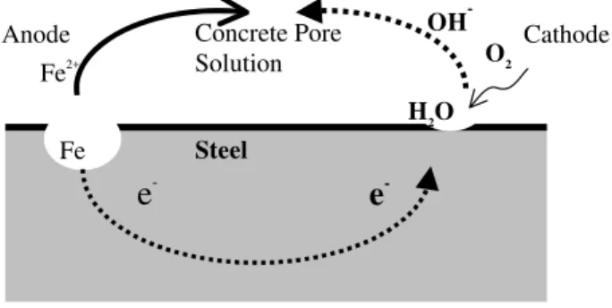
The corrosion of steel embedded in concrete is an electrochemical process in which the steel is oxidized at the anode (Fig. 1), and the electrons are released and flow to the cathode for the oxygen reduction reaction. As a result, a current circuit forms between the anode and cathode that flows through both the steel and concrete pore solution that acts as an alkaline electrolyte. Corrosion potential is a measure of the corrosion tendency of the steel, and the corrosion current density is a measure of how fast the corrosion process proceeds, which is related to both the corrosion potential and electrical resistance of the electrolyte. Based on the electrochemical nature of corrosion of steel embedded in concrete (Fig. 1), a repair of corrosion-induced damage must aim at achieving one or more of the following objectives: 1) to stop the anodic process; 2) to stop the cathodic process; and/or 3) to stop the electrolytic conduction process (RILEM 1994). For a patch repair therefore, it means that at least the anodic reaction should be prevented from recurring in the repaired area.
Many patch repairs, however, have been found to last from only a few months to a year before the appearance of new corrosion damage. The major cause of degradation of the repairs arises from the adverse interaction between the repaired area and adjacent unrepaired areas (called substrate), which stems from (a) poor performance of the repaired area due to mechanical failures (Cusson and Mailvaganam 1996) and hence a recurring corrosion risk; and/or (b) new corrosion induced in the substrate or at the interface of the patch and the substrate.
Although inadequate durability of patch repairs due to corrosion attack is prevalent, the current knowledge of the mechanism is far from sufficient to make an effective strategy. Figure 2 presents the corrosion activities after a patch repair that could occur in three areas: repaired area, substrate or their interface. In terms of its location, type and scope, corrosion in a patch repair system is complex in that it involves not only the properties of the patching materials and surface treatment on the steel, but also the conditions in the existing substrate, interfacial properties, in-service conditions and mechanical loadings. These key factors are illustrated in the Fig. 2. The problem is further compounded by poor workmanship.
Our limited understanding of the complexity of the corrosion process in patch repairs is shown by the fact that even a repair with a good patching material (low permeability and good bonding capability) installed with proper workmanship does not eliminate the risk of new active corrosion after repair. The initiation of active corrosion—due to repair— has often been noted to occur in the substrate or at the interface. This is known as ring-anode effect, and has been attributed to macrocell corrosion formed between the steel in the repaired patch (cathode) and the steel in the substrate (anode). The prevailing understanding is that the electrochemical incompatibility
between the patch and substrate is mainly responsible for this type of corrosion. The principles of electrochemical incompatibility have been widely discussed (Emberson and Mays 1990; Raupach 1996; Gu et al. 1997; Emmons and Vaysburd 1997; Mailvaganam 2001) and the existence of macrocell corrosion has been experimentally demonstrated (Wheat and Harding1993; Schieβl and Breit 1996; Pruckner and Gjφrv 2002; Castro et al. 2003; Li and Yuan 2003; Cusson et al. 2004).
Consequently, macrocell corrosion has been used to explain the corrosion in the substrate induced by the repaired area. The characteristics of the macrocell corrosion ⎯ such as corrosion current distribution and density⎯ that directly lead to deterioration, and the key factors that affect these characteristics however, are not well understood. Furthermore, a more fundamental question as to whether the induced corrosion in the substrate is due to macrocell or microcell (or uniform) corrosion or both has not been fully addressed. For example, Andrade et al. (1992) emphasized that both microcell and macrocell corrosion could co-exist in active corrosion, and a newly induced macrocell might not necessarily suppress the existing microcell corrosion. Since the technique that measures macrocell corrosion cannot measure microcell corrosion, the contribution of the latter is easily overlooked and the real degree of total corrosion could be seriously underestimated.
This paper commences with an explanation of the theoretical considerations pertaining to the correlation between microcell and macrocell corrosion. Subsequently, this is used as the basis for a critical review of corrosion in patch repairs and the focus is the three possible corrosion locations (patch, interface, and substrate) and the controlling factors. It is hoped that such a
review will enhance our current understanding and enable the identification of future research needs for successful patch repairs.
2. Corrosion Characteristics in Patch Repairs
2.1.Correlations of Microcell and Macrocell Corrosion
The protective high pH of a sound concrete, such as in a newly repaired area, normally passivates the embedded reinforcing steel. A passive steel is characterized by a high open circuit potential and a negligible corrosion rate. If this protective environment is contaminated by chlorides and/or carbonation, active corrosion can initiate at the steel surface. An active steel is characterized by a low open circuit potential and a high corrosion rate that is normally greater than 0.1-0.2 μA/cm2
(Andrade and Gónzalez 1978).
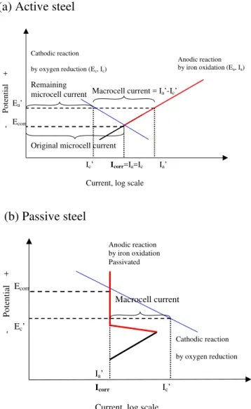
Active corrosion may consist of innumerable microcells in which the anodes and cathodes are so closely located that the effect of electrical resistance of the electrolyte is negligible. The corrosion kinetics can be illustrated by the correlation between the corrosion potentials and currents at the anode and cathode, respectively, using an Evan’s diagram (Fig. 3). At the anode, the iron ions and electrons are released at a rate measured by the anodic corrosion current Ia,
which in log scale is in linear relation with the anodic corrosion potential Ea, as shown by the
straight line of (Ea, Ia) in Fig. 3(a). At the cathode, the oxygen reduction rate is controlled by the
consumption of the electrons released from the steel oxidation reaction, as measured by the cathodic corrosion current Ic. In log scale Iccan be in linear relation with the cathodic corrosion
potential Ec, as shown by the straight line of (Ec, Ic) in Fig. 3(a). When an equilibrium is
achieved, the cathode and anode will reach the same potential (considering the zero resistance of electrolyte), called the corrosion potential Ecorr; the law of mass conservation requires the
electrons that are released at the anode to be consumed at the cathode at the same rate, denoted by a corrosion current Icorr. In summary, the equilibrium state of a steel under corrosion can be
characterized by the following equations:
[1] Ecorr = Ea = Ec
[2] Icorr = Ia = Ic
When this active steel is put in electrical contact with a passive steel having a more positive potential at the equilibrium, the equilibrium as shown Eq. 1 and Eq. 2 will be interrupted on each of the steels. Take the example of the active steel; it will be anodically polarized from its equilibrium Ecorr to a new higher potential Ea’, as illustrated in Fig. 3(a). At this new potential
the steel oxidation is increased to Ia’ but the oxygen reduction reaction on its surface is reduced
to Ic’. In other words, the reduction reaction can no longer consume the electrons produced in the
oxidation reaction. Consequently, the extra electrons flow from this active steel to the passive steel, forming a corrosion macrocell between the two steels. The macrocell current from the active steel, Imacro, is caused by the difference between the increased oxidation reaction and the
decreased reduction reaction, as quantified by Eq. 3.
[3] Imacro = Ia’ –Ic’
On the other hand, the reactions on the passive steel and change in the corrosion potential follow the opposite trend. As shown in Fig. 3(b), the new potential Ec’ will be lowered; the oxygen
reduction reaction will be enhanced by consuming the electrons flowing in from the active steel. Although their respective local equilibriums are interrupted (the local oxidation and reduction reaction rates are no longer in balance), a new “global” equilibrium will be reached between the active and passive steel, as the macrocell current flowing between them becomes stable. Since
the electrons flow from the active steel to the passive steel, it is easy to identify (by experiment) that the former serves as the anodic site and the latter the cathodic site in the macrocell.
In summary, after a macrocell corrosion forms between the active steel and passive steel, the oxidation of the active steel will be enhanced, but its oxygen reduction will be diminished. It should be noted however, that it is not the macrocell current Imacrobut the total anodic current Ia’
that determines the dissolution rate of the active steel. From Eq. 3, it is seen that the total anodic current Ia’ consists of two parts: the macrocell current, Imacro, and the remaining microcell current
to balance the local oxygen reduction Ic’.
Thus, it has been shown that both macrocell and microcell currents exist on the anode of a corrosion macrocell. The relevant question is whether or not the formation of macrocell suppresses the microcell corrosion, which can be determined by comparing the magnitude of the prevailing microcell corrosion rate Ic’ with the original corrosion rate Icorr. Their correlation
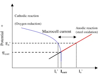
depends on the shape of the oxygen reduction curve. In concrete, corrosion rate if often controlled by the availability of oxygen diffused into the concrete, and such oxygen diffusion-controlled corrosion can be illustrated by a steep curve of oxygen reduction as shown in Fig. 4. Under such a condition, the macrocell corrosion hardly reduces the microcell corrosion, for the remaining microcell corrosion rate Ic’ is approximately the same as the original corrosion rate
Icorr. This was also illustrated by Andrade et al. (1992) in an explanation of correlation between
macrocell and microcell corrosion.
Many experiments have detected macrocell current flow between sites on the reinforcing steel in the patch and substrate (Wheat and Harding, 1993; Schieβl and Breit, 1996; Pruckner and Gjφrv,
2002; Castro et al. 2003; Li and Yuan, 2003), which is the main reason for the current understanding that the macrocell corrosion is the main corrosion mechanism in patch repair systems. The above theoretical illustrations however, convey an important message: not only does microcell corrosion coexist with macrocell corrosion but also its magnitude could be a significant part of the total corrosion.
2.2.Corrosion Mechanism of Steel in Substrate of Patch Repairs
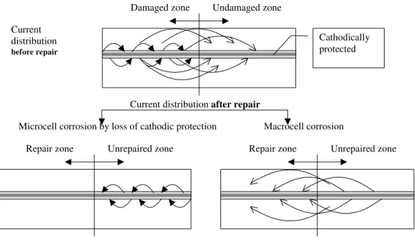
Corrosion after a patch repair can occur either in the patch or in the substrate. In most cases, however, it is observed that the steel in the substrate undergoes more active corrosion than in the patch. This is mainly due to the fact that the substrate concrete, either by chloride contamination or carbonation, is usually more corrosive than concrete in the newly repaired area. Corrosion in the substrate, induced by patch repair, can be attributed to two corrosion mechanisms, microcell and macrocell corrosion, as described below and illustrated in Fig. 5. Either of the two types of corrosion can have a significant rate that explains the observed corrosion damage in the substrate, and it is also possible that both of them play equally important roles.
(a) Microcell corrosion by loss of cathodic protection:
Raupach (1996) explained the corrosion activities before and after a patch repair in order to illustrate the changes induced by the repair. The damaged area, before the repair, was more corrosive to the steel than the substrate and therefore served as an anodic (active) corrosion site, the adjacent substrate being cathodically protected. This is illustrated by the current flow from the damaged area (anode) to the substrate (cathode) in the upper plot of Fig. 5 (only the current flow in the concrete is illustrated, and the direction of electron flow is opposite). After repair, the corrosive environment in the damaged area is removed and consequently, its cathodic protection
on the steel in the substrate is lost. As a result, the steel in the substrate can develop active microcell corrosion, as shown in the lower-left plot in Fig. 5. It is important to note that this type of corrosion cannot be detected by the commonly used technique of using a zero resistance Ampere meter to detect the macrocell corrosion (Schieβl and Breit 1996).
(b) Macrocell corrosion induced by incompatibility
Gu et al. (1997) used basic electrochemical principles to illustrate two cases of the macrocell corrosion, in which the anodic site could be either in the substrate or in the patch. For example, the first case is a repair to a chloride contaminated concrete substrate. As illustrated in Fig. 6, because the chloride concentration in the substrate is higher than in the patch, it corrosion potential, denoted by E2 in the figure, is correspondingly lower that that in the patch (E1). As a
result, the macrocell corrosion forms between the patch and the substrate, and the steel in the substrate serves as the anode and undergoes active corrosion. The second case is a repair that uses dense patching material and is surrounded by a more porous concrete substrate. Because the oxygen concentration in the substrate is higher than in the patch, its corrosion potential will be higher so that the steel in the patch serves as the anode. However, experimental investigations have shown that the second case ⎯oxygen gradient corrosion in the patch⎯ is unlikely to occur under in-service conditions because the steel in the patch is most likely to be passivated (Li and Yuan 2003).
2.3. Macrocell Corrosion Characteristics
Since many experiments have detected the macrocell corrosion in patch repairs, it is necessary to consider the controlling factors such as driving force, current density and current distribution, involved in this type of corrosion, in order to create methods to counteract it.
The driving force for the corrosion macrocell has been attributed to the electrochemical incompatibility between the patch and substrate. The electrochemical incompatibility is the imbalance in electrochemical potential between different locations of the reinforcing steel because of their dissimilar environments caused by a patch repair (Gu et al. 1997). The dissimilar environments can be due to the differences in both physical properties (e.g., porosity) and chemical compositions. The resultant electrochemical potential imbalance can be as high as 500 mV (Pruckner and Gjorv 2002).
The current distribution within a macrocell depends on the electrical resistance to the passage of current across the steel-concrete interface and through the concrete, which in turn determines the cell characteristics, such as corrosion rate, length of the cell, etc. Barkey (2004) used a Wagner number (W) to account for the influence of the two types of resistance:
[5] L R W p ⋅ = ρ
where Rp ( Ω.m2) is the polarization resistance of the metal-concrete interface, ρ is the bulk
resistivity of the concrete (Ω.m), and L (m) is a characteristic length scale of the macrocell. If W is much greater than 1, the distribution of current is controlled by the surface overpotential; if W is less than 1,the ohmic overpotential is controlling. The geometry of the macrocell, as characterized by the length L, determines the distribution and rate of corrosion (Barkey 2004).
Barkey (2004) found that the geometry of a macrocell was controlled by the concrete resistivity that limited the penetration of current into the substrate (anode) within 10 cm of the interface between the substrate and patch, the length of the anode being about 5-10 cm. Andrade et al.
(1992) concluded from their transmission line modeling that the coplanar anode and cathode in a macrocell (such as that in patch repair systems) were limited to a short distance beyond their interface. Similarly, the experiments conducted by Castro et al. (2003) showed that the anodic sites in the substrate were within 10-20 cm of the interface.
Since the resistivity of concrete was found to be a key factor controlling the macrocell corrosion, Barkey (2004) indicated that the water content of concrete played a critical role in determining the characteristics of macrocell corrosion. Schieβl and Breit (1996) confirmed experimentally that the water content in concrete was the biggest factor in controlling the macrocell corrosion rate. Similarly, Castro et al. (2003) found that the increased concrete resistivity due to the drying and continuing hydration of the cement played a significant role in attenuating the degree of macrocell corrosion and reducing its duration. Li and Yuan (2003) reported that the area ratio between cathode/anode was a function of moisture content; the wetter the specimen, the lower the ratio. Thus, they concluded that the ratio of 2 found at 95% RH was approximately the minimum area ratio between cathode/anode.
2.4. Practical Implications
In practice, macrocell corrosion caused by electrochemical incompatibility has been used to explain corrosion in the substrate near the repaired area. At the same time, the possibility of microcell corrosion has been overlooked in the process that might be a significant part of the total degree of corrosion. This, in part, is due to the fact that the detection technique for macrocell corrosion is not able to detect the presence of microcell corrosion. Since either microcell or macrocell corrosion, or both, can be the main reasons(s) for corrosion damage in the
substrate near patch repairs, great attention should be paid to the underlying mechanisms in order to clarify the two issues given below:
1) Even if the macrocell is detected in patch repairs (often the case), the total anodic corrosion rate is not known without measuring the coexisting microcell corrosion (see Section 2.1).
2) If the macrocell corrosion is not detected in patch repairs, it does not eliminate the corrosion risk in the substrate without measuring the microcell corrosion which itself can exist and develop after a repair (see Section 2.2).
Therefore, it is critical to first address the coexistence of microcell corrosion with macrocell and then differentiate the relative degree of participation of the two corrosion mechanisms. Some available data allow us to compare the densities of the two corrosion activities. For example, Li and Yuan (2003) showed that the microcell corrosion in the chloride contaminated substrate—as recorded in their experimental set up— was approximately 1.1 μA/cm2
, both before and after the repair, while the induced macrocell corrosion after the repair was at a rate of 2 μA/cm2
. It can be seen that both the microcell corrosion, detected by the linear polarization method, and the macrocell corrosion, detected by the zero resistance Ampere meter, were significantly high.
Distinguishing between the degree of participation of both microcell and macrocell corrosion under different conditions goes beyond theoretical interest—it is also critical for a correct repair strategy as is discussed below.
(1) If the corrosion in the substrate is mainly the microcell corrosion induced by the loss of cathodic protection originally provided by the damaged area, measures must be taken to depress the active corrosion in the substrate.
(2) If the corrosion is mainly macrocell corrosion, any measures that can diminish the cathodic corrosion (e.g. coating the steel) or increase the electrical resistivity to the current path (e.g. using resins as patching material) will diminish the anodic corrosion in the substrate.
(3) If these two mechanisms co-exist and the contribution from each is significant, multiple measures must be employed to stop the corrosion.
3. Key Factors and Locations of Corrosion in Patch Repairs
The following review—based on the fundamentals discussed above and literature of experimental studies— explains how the key factors influence corrosion in patch repair systems.
3.1. Governing Factors for Corrosion in Substrate
3.1.1. Condition of the substrate
The prevailing condition of the substrate— particularly the chloride content— plays an important role in determining whether the macrocell forms or not after a patch repair. There is a consensus of opinion that patch repair induces or enhances the active corrosion of steel embedded in the substrate if its chloride content is above a certain threshold level and sufficient moisture is present. Schieβl and Breit (1996) reported that no corrosion was induced in the steel embedded in the substrate having a low chloride content (0.5% by cement weight). However, in another substrate with high chloride content (2% by cement weight) in which corrosion had been initiated before repair, the repair enhanced active corrosion. Li and Yuan (2003) confirmed similar findings in their work done on a substrate with 5% chlorides (by cement weight) and reported that the corrosion rate was increased by 1.5 to 2 times after repair.
This finding therefore appears to dictate the removal and repair of all concrete contaminated with chlorides or carbonation—whether the damage is visible or not. But how extensively should the concrete be removed? From a structural viewpoint, a patch repair should not detract from integrity of the structure. Consequently, the repair should interfere with the structural system as little as possible (RILEM 1994). This was stressed by Weyers et al. (1993) that the maximum depth of removal should not exceed half the deck thickness of a bridge. From a corrosion viewpoint, a significant amount of the concrete should be removed to eliminate much of the contaminated concrete. For example, a partial-depth repair due to the corrosion of the top reinforcing mat in a bridge deck would require that concrete be removed to a depth of at least of 20 mm below the top layer of reinforcing steel (Bentur et al. 1996).
3.1.2. Concrete patching material
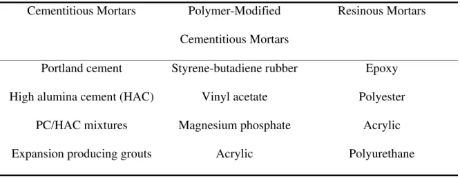
There are a variety of patching materials in the market with a range of ingredients (e.g. polymer lattices and corrosion inhibitors) and properties that address specific requirements such as fast set and rapid strength development. They can be categorized into three generic groups as shown in Table 1. Some of these materials have been tested under both laboratory and field conditions. Most of the studies however, limited their evaluations to the properties of the patching materials themselves (Cleland et al. 1997; Cabrera and Hasan 1997; Kasselouri et al. 2001). The risk of inducing corrosion in the patch area or adjacent substrate, when these patching materials were used, has not normally been addressed.
Current patching materials often include a corrosion inhibitor in their formulations. A three year field monitoring of the performance of patch repairs containing corrosion inhibitors by Cusson et al. (2004) indicated that the potential difference between the patch containing corrosion inhibitor
and substrate was around 100-150 mV and increasing with time. It was therefore, concluded that the risk of corrosion in the substrate would increase with time (Cusson et al. 2004). The efficacy of using corrosion inhibitors was challenged by Vaysburd and Emmons (2004) for two reasons: 1) the patching materials with corrosion inhibitors may just form a cathodic area that stimulates corrosion around it; and 2) it is difficult to maintain the necessary concentration of inhibitors. Another practice in the formulation of patching compounds is to use a resin (e.g. epoxy) as the primary patching material. Because the resin matrix is not electrically conductive and impermeable to oxygen, the macrocell corrosion cannot be formed with the unrepaired area (Li and Yuan 2003).
3.1.3. Steel surface treatment
The surface treatment of steel could be achieved in three ways: 1) natural repassivation by the alkaline pH of the patching materials; 2) creation of an electrical barrier to insulate the steel through the use of an epoxy coating; 3) cathodic protection by using a zinc rich coating. Schieβl and Breit (1996) found that coating of the steel in repaired area using electrical insulating materials based on epoxy-resins prevented macrocell formation with the adjacent substrate. However, they also reported that there existed other large regions of passivated steel that could form corrosion macrocells with the substrate near the patch. Similarly, Raupach (1996) argued that by using adequate coating, the cathodic reaction rate can be significantly reduced in these areas, but it cannot prevent the occurrence of corrosion near the patch areas, because in most cases there are other steel surface areas with varying degrees of passivity.
3.2.Corrosion at Interface
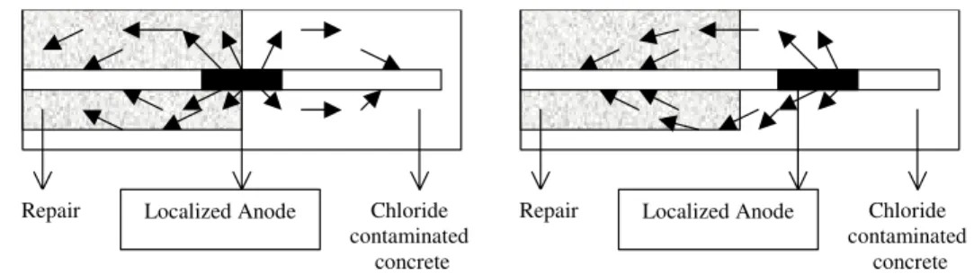
Although the incipient corrosion (or anode-ring corrosion) around the repaired area is now a well known problem, the precise location of the anodic site —whether it is in the substrate or at the interface— is not clear. There are two totally opposite experimental findings. Castro et al. (2003) closely monitored the current flow between segmented steel bars to identify the interfacial corrosion and corrosion in the substrate. They found the interface was mostly anodic, which was directly controlled by the corrosion activity in the patch (cathode). The corrosion in the substrate was in turn determined by the corrosion activity at the interface. This is illustrated by the corrosion current distribution in Fig. 7(a), in which the current flow (only the current flow in the concrete is illustrated, and the direction of electron flow would be opposite) is from the interface to both the patch and substrate. According to their experimental setup, the anodic site extended in both directions (patch and substrate) for 4 cm from the interface.
Barkey (2004) reported however, that the interface remained passive and suggested that this passive region might extend out of the repaired region into the substrate (anode). An examination of the corrosion products revealed that the inner boundary of the anode in the substrate was 1 cm or 2 cm from the interface. According to his model, as illustrated in Fig. 7(b), the macrocell current by-passed the interface, driving the chlorides out of this region with a possible high speed of 2 to 3 mm/month under a macrocell potential to 300 mV. As a result, the interface was protected from corrosion and remained passive.
Further study to clarify the corrosion location (either at the interface or in the substrate) is important to understanding the mechanism. Castro et al.’s model implied that the interface between the patch and substrate was the most critical factor for the induced corrosion, and
therefore a strong bond should be beneficial. In contrast, Barkey’s model showed the steel at the interface was in a passive state bypassed by the macrocell current. Clarification of the mechanism also has a bearing on the use of inhibitors. For example, according to Castro et al.’ s model, an inhibitor applied at the interface needs to maintain a certain level of concentration to be effective in suppressing corrosion. On the other hand, according to Barkey’ model, an inhibitor applied at the interface needs to migrate into the substrate to suppress the corrosion reactions.
3.3. Corrosion in Repaired Concrete
Cleland et al. (1997) evaluated different properties of repair materials in a substrate made of sound concrete in which the steel remained passive. They found that when the patches were exposed to chloride ponding, corrosion was induced in the patches because the patching materials had a higher permeability than the substrate. Similar results were reported when the Silica Fume-Calcium Hydroxidecompositions were used as patching materials (Kasselouri et al. 2001); the corrosion rates in the patches were higher because of their high porosity during the hydration process. Their results indicated that proper curing of patches prior to exposure to chloride ingress is important, because the patching materials would need time to achieve their designed properties. These experiments are not however, representative of field conditions where the concrete substrate is often degraded, chloride contaminated or carbonated when a repair is done. The results of such tests therefore, cannot be used to predict the performance of patch repairs in the field.
3.4. Compatibility of Patching and Substrate Materials
The above review examined the key factors for the three possible corrosion locations: substrate, repaired zone, and interface, respectively. It is clear that their different electrochemical environments due to their different material properties and steel surface treatments determine the location of corrosion. This fact has also led to the prevailing understanding that the compatibility of repair materials with the substrate (Emmons et al. 1994; Mailvaganam 2001) is most critical for a successful patch repair.
Compatibility in this regard is a measure of matching physical, chemical, electrochemical and dimensional properties between the patching materials and substrate concrete. To this end, Emmons and Vaysburd (1997) listed the difference between new construction and repair jobs as a guide for proper selection of repair strategies, and Cusson and Mailvaganam (1996) suggested patch repairs themselves should be classified as structural or non-structural. Furthermore, Mailvaganam (2001) pointed out that both the characteristics of a repair material and its response to the prevailing ambient conditions during installation and the in-service environment should be considered (e.g., a selected material should be less sensitive to ambient conditions such as temperature and humidity if these conditions are less controlled in rehabilitation.).
The achievement of compatible performance is yet to be resolved. Many studies (e.g. ACI 546 R- Concrete Repair Guide; Emberson and Mays 1990) have specified the properties ⎯ such as bond and compressive strength, elastic modulus, thermal expansion coefficient, etc.⎯ of a patching material that are considered important to be compatible with the substrate. However, whether these criteria will ensure a compatible performance has yet to be established. Thus under this context, it seems that there exist no “good” or “bad” patching materials without a holistic
consideration of material characteristics together with the substrate condition and the environment. The assertion by Wheat and Hardening (1993) that the compatibility should be based on the performance attests to the fact that a holistic approach is necessary.
A compatible performance between the patch and substrate might be able to eliminate the macrocell corrosion. It is most important to note however, that it will not ensure full corrosion protection in the substrate near the patch, because of the possible presence of microcell corrosion developed in substrate as explained in Section 2.2.
It is also important to recognize the inherent limitation of patch repair that stems from the fact that the underlying cause of corrosion is more extensive than what is evident in the area of visible damage. Vaysburd and Emmons (2004) even suggested that the concept of patch repair itself might not be a good concept because the local protective systems in the repair contribute to the existing “non-uniformity” in the substrate, thereby increasing the risks of new corrosion activity. Understanding these fundamentals will be helpful to set a realistic goal for a patch repair and to select an effective repair method that conforms to the objectives of the goal.
4. Conclusions and Future Research Perspectives
This paper presented the correlation between macrocell and microcell corrosion and showed that microcell corrosion should not be overlooked in assessing the degree of corrosion in patch repairs. The fundamental corrosion mechanism in patch repairs can microcell or macrocell corrosion, or both, and must be considered when designing a successful repair strategy.
Different electrochemical environments in the patch and substrate ⎯due to their different material properties and surface treatments substrate⎯ are the key factors that determine the locations of active corrosion in the substrate, repaired zone, and interface, respectively. The compatibility of the patching and substrate material might be able to eliminate the macrocell corrosion, but it will not ensure full corrosion protection in the substrate because of the possible presence of microcell corrosion.
It is concluded that the corrosion mechanisms in patch repairs are not fully understood and this has therefore, impeded the development of an effective and durable repair strategy. The authors suggest that future studies should address aspects pertinent to the following two questions via laboratory investigations and well-documented field studies:
(1) Which corrosion activity— macrocell or microcell— in the adjacent substrate controls the rate of steel dissolution?
(2) In the macrocell corrosion, is the anodic site at the interface or in the substrate? What are the anodic corrosion characteristics with regards to its geometry and current density?
5. Reference
Alonso, C., Andrade, C., and Gonzalez, J.A. 1988. Relation between resistivity and corrosion rates of reinforcement in carbonated mortar made with several cement types. Cement and Concrete Research, 18: 687-698.
Andrade, C. and Gonzales, J.A. 1978. Quantitative measurement of corrosion rate of reinforcing steels embedded in concrete by polarization resistance measurements. Werkstoffe und Korrosion, 29: 515-519.
Andrade, C., Maribona, I. R., Feliu, S., Gonzalez, J. A., and Feliu, S. Jr. 1992. The effect of macrocells between active and passive areas of steel reinforcement. Corrosion Science, 33: 237-249.
Barkey, D.P. 2004. Corrosion of steel reinforcement in concrete adjacent to surface repairs. ACI Materials Journal, 101: 266-272.
Bentur, A., Diamond, S., and Berke, N. S. 1996. Steel corrosion in concrete. E&FN SPON, London.
Cabrera, J. G., and Al-Hasan, A. S. 1997. Performance properties of concrete repair materials. Construction and Building Materials, 11: 283-290.
Castro, P., Pazini, E., Andrade, C., and Alonso, C. 2003. Macrocell activity in slightly chloride-contaminated concrete induced by reinforcement primers. Corrosion, 59: 535-546.
Cleland, D.J., Yeoh, K. M., and Long, A. E. 1997. Corrosion of reinforcement in concrete repair. Construction and Building Materials, 11: 233-238.
Cusson, D. and Mailvaganam, N. P. 1996. Durability of repair materials. Concrete International,
18: 34-38.
Cusson, D., Hoogeveen, T., and Qian, S. 2004. Field Performance monitoring and evaluation of concrete repair systems on a highway bridge. 5th Structural Specialty Conference of the Canadian Society for Civil Engineering, Saskatoon, Canada, ST-198-1 to ST-198-10.
Emberson, N.K. and Mays, G.C. 1990. Significance of properties mismatch in the patch repair of structural concrete Part 1 properties of repair systems. Magazine of Concrete Research, 42: 147-160.
Emmons, P.H., and Vaysburd, A.M. 1997. Corrosion protection in concrete repair: myth and reality. Concrete International, 19: 47-56.
Gu, P., Beaudoin, J. J., Tumidajski, P. J., and Mailvaganam, N. P. 1997. Electrochemical incompatibility of patches in reinforced concrete. Concrete International, 19: 68-72.
Kasselouri, V., Kouloumbi, N., and Thomopoulos, T.H. 2001. Performance of silica fume-calcium hydroxide mixture as a repair material. Cement and Concrete Composites, 23: 103-110.
Li, G., and Yuan, Y.S. 2003. Electrochemical incompatibility for patch-repaired corroded reinforced concrete. Journal of China University of Mining and Technology, 32: 44-47.
Mailvaganam, N. P. 2001. Concrete repair and rehabilitation: Issues and trends. The Indian Concrete Journal, 75:759-764.
Pruckner, F. and Gjφrv, O.E. 2002. Patch repair and macrocell activity in concrete structures. ACI Materials Journal, 99: 143-148.
Raupach, M. (1996). Chloride-induced macrocell corrosion of steel in concrete--theoretical background and practical consequences. Construction and Building Materials, 10: 329-338. RILEM Draft Recommendation (1994), Repair strategies for concrete structures damaged by
reinforcement corrosion, Materials and Structures, 27:415-436.
Schieβl, P. and Breit, W. 1996. Local repair measures at concrete structures damaged by reinforcement corrosion – aspect of durability. International Symposium on Corrosion of Reinforcement in Concrete Construction, Royal Society of Chemistry, SP 183: 327-336. Vaysburd, A.M., and Emmons, P.H. 2004. Corrosion inhibitors and other protective systems in
concrete repair: concepts or misconcepts. Cement and Concrete Composites, 26: 255-263. Weyers, R.E., Prowell, B.D., Sprinkel, M.M., and Vorster, M. 1993. Concrete Bridge Protection,
Repair, and Rehabilitation Relative to Reinforcement Corrosion: A Methods Application Manual, SHRP-S-360, Strategic Highway Research Program, National Research Council, Washington, D.C.
Wheat, H.G., and Harding, K.S. 1993. Galvanic corrosion in repaired reinforced concrete slabs-an update. Materials Selection slabs-and Design, 5: 58-62.
Table 1 Generic systems for patch repair (Emberson and Mays 1990) Cementitious Mortars Polymer-Modified
Cementitious Mortars
Resinous Mortars
Portland cement Styrene-butadiene rubber Epoxy
High alumina cement (HAC) Vinyl acetate Polyester
PC/HAC mixtures Magnesium phosphate Acrylic
Figure 1. Possible anodic corrosion sites and key factors in patch repair system Figure 2. Steel corrosion process and current flow in concrete
Figure 3. Schematic of macrocell and microcell corrosion, (a) active steel; (b) passive steel Figure 4. Schematic of macrocell corrosion and microcell corrosion of active steel by oxygen
diffusion control
Figure 5. Schematic of two corrosion mechanisms in unrepaired area
Figure 6. Schematic of electrochemical incompatibility between a repaired area and unrepaired area contaminated by chloride (adapted from Gu et al. 1997)
Figure 1. Possible anodic corrosion sites and key factors in patch repair system
Unrepaired concrete substrate
Patching material Steel surface treatment
Corrosion in repaired area Corrosion at interface
Corrosion in substrate
Figure 2. Steel corrosion process and current flow in concrete
OH
-e
-Anode Concrete Pore Cathode
Solution Steel O2 H2O Fe2+ Fe e
-Figure 3. Schematic of macrocell and microcell corrosion, (a) active steel; (b) passive steel
(a) Active steel
Pot ent ial + Anodic reaction by iron oxidation (Ea, Ia)
Current, log scale Cathodic reaction by oxygen reduction (Ec, Ic) Ecorr Icorr=Ia=Ic Ea’ Ic’ Ia’
Macrocell current = Ia’-Ic’
Remaining microcell current
Original microcell current
(b) Passive steel Potentia l + Anodic reaction by iron oxidation Passivated
Current, log scale
Cathodic reaction by oxygen reduction Ecorr Icorr Ec’ Ia’ Ic’ Macrocell current
Figure 4. Schematic of macrocell corrosion and microcell corrosion of active steel by oxygen diffusion control Poten tial + Anodic reaction (steel oxidation)
Current, log scale
Cathodic reaction (Oxygen reduction) Ecorr Icorr Ea’ Ic’ Ia’ Macrocell current
Figure 5. Schematic of corrosion mechanisms before and after repair
Current distribution
before repair
Damaged zone Undamaged zone
Repair zone Unrepaired zone Repair zone Unrepaired zone
Cathodically protected
Current distribution after repair
Figure 6. Schematic of electrochemical incompatibility between a repaired area and unrepaired area contaminated by chloride (adapted from Gu et al. 1997)
- Po te ntial + Anodic reaction Iron corrosion
Current, log scale
Electrochemical Incompatibility Cathodic reaction (Oxygen reduction)
Steel in repaired zone (Chloride free)
Steel in unrepaired zone (Chloride contaminated)
Figure 7. Macrocell current distribution in patch repair, a) Castro et al.’s model; b) Barkey’s model
Chloride contaminated
concrete
Repair Localized Anode Chloride
contaminated concrete Repair Localized Anode
1. Introduction... 3
2. Corrosion Characteristics of Patch Repairs ... 6
2.1. Correlations of Microcell and Macrocell Corrosion... 6
2.2. Corrosion Mechanism of Steel in Substrate of Patch Repairs ... 9
2.3. Macrocell Corrosion Characteristics... 10
2.4. Practical Implications... 12
3. Key Factors and Locations of Corrosion in Patch Repairs ... 14
3.1. Governing Factors for Corrosion in Substrate ... 14
3.1.1. Condition of the substrate ... 14
3.1.2. Concrete patching material ... 15
3.1.3. Steel surface treatment... 16
3.2. Corrosion at Interface ... 17
3.3. Corrosion in Repaired Concrete... 18
3.4. Compatibility of Patching and Substrate Materials ... 19
4. Conclusions and Future Research Perspectives... 20