Automated Verification of Model-based Programs
Under Uncertainty
by
Tazeen Mahtab
Submitted to the Department of Electrical Engineering and Computer Science in Partial Fulfillment of the Requirements for the Degrees of
Bachelor of Science in Computer Science and Engineering
and Master of Engineering in Electrical Engineering and Computer Science at the Massachusetts Institute of Technology
May 20, 2004 DLun a 20CA
Copyright 2004 Tazeen Mahtab. All rights reserved.
ASSACH STS INSTUTE
OF TECHNOLOGY
JUL
2 0 2004
UIBRARIES
The author hereby grants to M.I.T. permission to reproduce and distribute publicly paper and electronic copies of this thesis
and to grant others the right to do so. Author... ...
Department of Electrical Engineering and Computer Science May 20, 2004 Certified by.... ... .... . . .... . . . . Gregory T. Sullivan Thesis Supervisor Certified by... ... Brian C. Williams n..T4is Supervisor Accepted by... ... Arthur C. Smith Chairman, Department Committee on Graduate Theses
Automated Verification of Model-based Programs
Under Uncertainty
by
Tazeen Mahtab
Submitted to the Department of Electrical Engineering and Computer Science May 20, 2004
In Partial Fulfillment of the Requirements for the Degrees of Bachelor of Science in Computer Science and Engineering
and Master of Engineering in Electrical Engineering and Computer Science
Abstract
Highly robust embedded systems have been enabled through software executives that have the ability to reason about their environment. Those that employ the
model-based autonomy paradigm automatically diagnose and plan future actions, model-based on
models of themselves and their environment. This includes autonomous systems that must operate in harsh and dynamic environments, like deep space. Such systems must be robust to a large space of possible failure scenarios. This large state space poses difficulties for traditional scenario-based testing, leading to a need for new approaches to verification and validation.
We propose a novel verification approach that generates an analysis of the most likely failure scenarios for a model-based program. By finding only the most likely failures, we increase the relevance and reduce the quantity of information the devel-oper must examine. First, we provide the ability to verify a stochastic system that encodes both off-nominal and nominal scenarios. We incorporate uncertainty into the verification process by acknowledging that all such programs may fail, but in dif-ferent ways, with difdif-ferent likelihoods. The verification process is one of finding the most likely executions that fail the specification. Second, we provide a capability for verifying executable specifications that are fault-aware. We generalize offline plant model verification to the verification of model-based programs, which consist of both a plant model that captures the physical plant's nominal and off-nominal states and a control program that specifies its desired behavior. Third, we verify these specifica-tions through execution of the RMPL executive itself. We therefore circumvent the difficulty of formalizing the behavior of complex software executives.
We present the RMPLVerifier, a tool for verification of model-based programs written in the Reactive Model-based Programming Language (RMPL) for the Titan execution kernel. Using greedy forward-directed search, this tool finds as counterex-amples to the program's goal specification the most likely executions that do not
achieve the goal within a given time bound. Thesis Supervisor: Gregory T. Sullivan Title: Research Scientist
Thesis Supervisor: Brian C. Williams
Title: Associate Professor of Aeronautics and Astronautics
Acknowledgments
I would like to begin by thanking my advisors, Greg Sullivan and Brian Williams, for their invaluable guidance and support in the completion of this thesis.
A huge thanks is due to Oliver Martin and Paul Elliott, for answering my innu-merable questions and always being ready to help. I could not have done it without you.
Thank you to everyone in the MERS group. It was great having the opportu-nity to work with you. A special mention goes to my fellow Tech Square residents, Jon Kennell, I-hsiang Shu, Raj Krishnan, Judy Chen, Stanislav Funiak, and Brad Hasegawa - I value your friendship. I would also like to thank Margaret Yoon, our administrative assistant.
To Tamara Yu and Yukie Tanino, thanks for getting me through my final year. Lastly, I wish to thank my family for their love and support.
This thesis was supported by a MOBIES grant from the Air Force Research Lab under Contract# F33615-00-C-1702.
Contents
1 Introduction 15
1.1 Motivation . . . . 17
1.2 Example of Verification on a Model-based P rogram . . . . 19
1.3 The RMPLVerifier . . . . 21
1.4 Thesis Layout . . . . 21
2 Related Work in Verification 23 2.1 Model Checking . . . . 24
2.1.1 Livingstone to SMV . . . . 24
2.1.2 Remote Agent . . . . 25
2.1.3 Rover Executive V & V Study . . . . 26
2.2 Executable Specifications . . . . 28
2.3 Simulation-based Verification . . . . 29
2.4 Summary . . . . 30
3 The RMPL Model-based Program 31 3.1 The Reactive Model-based Programming Language . . . . 32
3.2 The Model-based Program . . . . 37
3.3 T itan . . . . 39
3.3.1 Mode Estimation . . . . 39
4 The Verification Algorithm 4.1 Problem Statement ...
4.2 The Verification Process .
4.3 Overview of the Algorithm 4.4 Top-level Pseudocode . .
4.5 The Simulator . . . .
5 Verification of the Mars Entry Scenario
5 1 The Model-based Program for the Mars Entry Scena
5.2 Inputs ...
5.2.1 The Control Program.
5.2.2 The Goal Specification
5.2.3 The Plant Model . 5.2.4 Other Parameters .
5.3 Outputs . . . . 5.4 Walkthrough of the Algorithm 5.4.1 Time Step 0 . . . . 5.4.2 Time Step 1 . . . . 5.4.3 Time Step 2 . . . . 55 rio . . . . 55 . . . . 56 . . . . 57 . . . . 57 . . . . 58 . . . . 59 . . . . 65 . . . . 68 . . . . 70 . . . . 70 . . . . 71
5.4.4 The Remaining Time Steps . . . .
6 Implementation
6.1 System Architecture . . . . 6.2 Relevant Components of Titan . . . . 6.2.1 Sequencer . . . .
6.2.2 ModeEstimator . . . .
6.2.3 ValidSAT . . . .
6.3 Key Components of RMPLVerifier . . . . 6.3.1 Verifier . . . . 6.3.2 Simulator . . . . 6.3.3 SequencerInterfaceW ithObs . . . . 8 43 43 44 45 46 50 71 75 75 77 77 78 78 78 79 80 81 ... . . . . . . . . . . . . . . . . . . . . . . . .
6.4 Implementation Issues . . . . 6.5 Summary . . . .
7 Results and Conclusions
7.1 Performance . . . . 7.2 Future Work . . . . 7.2.1 Observations . . . . . 7.2.2 Performance . . . . 7.2.3 Presentation of Results 7.3 Summary . . . . . . . . 8 1 . . . . 8 2 83 83 85 85 86 86 87
List of Figures
1-1 The Mars Polar Lander. . . . . 20
1-2 The RMPL Control Program for the Mars Entry Scenario. . . . . 20
1-3 The Set of Plant State Trajectories Tracked by the RMPLVerifier. 20 3-1 The Mars Exploration Rover. . . . . 32
3-2 A Control Program for the Rover-Hazcam Scenario. . . . . 33
3-3 The Plant Model for the Rover-Hazcam Scenario. . . . . 35
3-4 The Architecture of the Titan Model-based Executive. . . . . 39
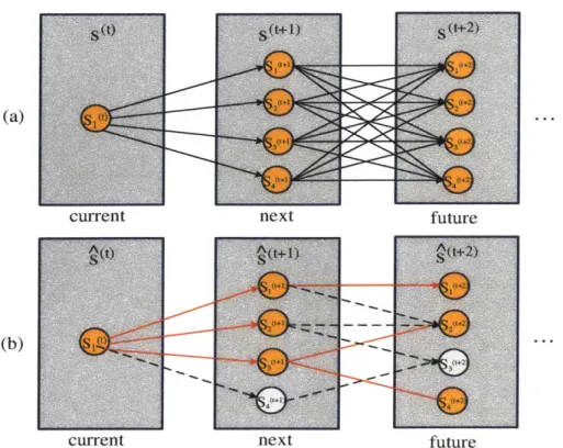
3-5 (a) A Trellis Diagram. (b) k Best Trajectories Mode Estimation. . . . 41
3-6 The k Most Likely Trajectories Algorithm. . . . . 42
4-1 The Verification Process. . . . . 44
4-2 A High-level View of the Algorithm. . . . . 46
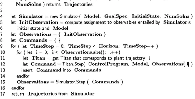
4-3 The Top-level Pseudocode of the Verification Algorithm. . . . . 47
4-4 The Beginning of the Verification Algorithm. . . . . 48
4-5 Relationship between a Titan trajectory and a Simulator trajectory. 49 4-6 The Simulator Pseudocode. . . . . 50
4-7 One step of the Simulator. . . . . 51
4-8 The Modified k Most Likely Trajectories Algorithm. . . . . 52
5-1 The Entry Sequence for a Mars Lander Spacecraft. . . . . 56
5-2 The RMPL Control Program for the Mars Entry Scenario. . . . . 57
5-3 The RMPL Control Program and Goal Specification for the Mars Entry Scenario. . . . . 58
5-4 The Plant Model for the Mars Entry Scenario. . . . . 59
5-5 The Att Component. . . . . 60
5-6 The Engine Component. . . . . 61
5-7 The Entry Component. . . . . 61
5-8 The Lander Component. . . . . 62
5-9 The Nav Component. . . . . 62
5-10 The PDE Component. . . . . 63
5-11 The Tank Component. . . . . 63
5-12 The Valve Component. . . . . 64
5-13 The Verification Output for the Mars Entry Scenario. . . . . 66
5-14 The Verification Output for the Mars Entry Scenario (Continued). . 67 5-15 Verification of the Mars Entry Scenario. . . . . 69
5-16 Verification of the Mars Entry Scenario (cont'd). . . . . 72
6-1 The UML class diagram for RMPLVerifier. . . . . 76
List of Tables
7.1 Performance of RMPLVerifier on the Mars Entry model-based program with respect to the number of time steps. . . . . 84
7.2 Performance of RMPLVerifier on the Mars Entry model-based program with respect to the number of trajectories. . . . . 84
Chapter 1
Introduction
Highly robust embedded systems have been enabled through software executives that have the ability to reason about their environment. Such systems must often operate in harsh and dynamic environments, like deep space, and therefore must be robust to a wide combination of potential failures. Those that employ the model-based
auton-omy paradigm automatically diagnose and plan future actions, based on models of
themselves and their environment. Model-based programming is an approach to de-veloping embedded systems that can reason about and control their hardware using corresponding software models [20]. A model-based program enables one to specify the desired state evolutions of the embedded system. It consists of a specification of be-havior, known as a control program, and a representation of the physical plant's nom-inal and off-nomnom-inal states, known as a plant model; these are run on a model-based
executive. Model-based systems have the ability to detect and respond to
unantici-pated failures on the fly. Therefore, they provide an increased assurance of reliability and fault awareness. However, such programs present a new challenge to verification. First, the large space of failure situations they handle poses difficulties for traditional scenario-based testing. Second, they are run on a complex execution algorithm. This leads to a need for new kinds of verification and validation [15].
Verification and validation (V6V) is an established methodology for ensuring
the quality and reliability of software systems. By definition, verification assures that a product satisfies its requirements at a given phase in the development cycle,
and validation assures that the final product satisfies the system requirements [16]. Previous verification efforts, such as the symbolic model checking of reactive programs
[3], have focused on determining the correctness of embedded programs. However,
in the real world, where embedded programs control real hardware, those systems are never guaranteed to succeed; they are more or less likely to succeed. We extend model-based system verification to the verification of model-based programs under uncertainty.
We propose a novel verification approach that generates an analysis of the most likely failure scenarios for a model-based program. First, we provide the ability to verify a stochastic system that encodes both off-nominal and nominal scenarios. We incorporate uncertainty into the verification process by acknowledging that all such programs may fail, but in different ways, with different likelihoods. Second,
by verifying model-based programs, we provide a capability for verifying executable
specifications that are fault-aware. A model-based system is never guaranteed to function correctly, since it always has some probability of not behaving nominally. Therefore, verification of these systems is a process of finding the most likely of these failure executions, rather than simply determining if there are any. Third, we verify these specifications through execution. We therefore circumvent the difficulty of formalizing the behavior of complex software executives by invoking the actual executive components.
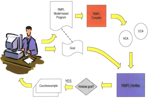
We present the RMPLVerifier, a tool for verification of model-based programs written in RMPL for the Titan execution kernel. The Reactive Model-based
Program-ming Language (RMPL) allows developers to perform high-level reasoning on the
behavior of a model. The RMPLVerifier uses greedy forward-directed search to ana-lyze an RMPL model-based program based on a goal specification and a given time bound. It then presents, as counterexamples, the most likely executions that lead to failure i.e. non-achievement of the stated goal. We analyze the results of applying our verification approach to the Mars Entry scenario, a significant model-based program specifying the entry sequence for a lander spacecraft.
The remainder of this chapter will motivate the verification of model-based
grams, relate verification to the Mars Entry scenario, and give an overview of the RMPLVerifier.
1.1
Motivation
Our verification approach provides three capabilities. We examine and motivate each of these in turn.
The first contribution of our approach is the ability to verify a stochastic system that encodes both off-nominal and nominal scenarios. In the past, one created robust embedded systems by attempting to enumerate ahead of time all possible failures the system could encounter. These systems were limited by the ability of the software development team. If a system encountered a failure that had not been predeter-mined by the developers, possible because of the many complex interactions between the hardware and software and the environment, it could fail to react properly. For example, the failure of the Mars Polar Lander is thought to have occurred because of unexpected leg sensor readings as it attempted to land. The software erroneously concluded from these readings that the Lander had touched down on the surface and prematurely shut off the engines, leading to the loss of the craft. New intelligent systems have been created to address this problem [20]. Rather than being prepro-grammed with all failures, these systems have the ability to deduce if they are in a nominal or failure state and to respond accordingly. These systems are stochastic, as they maintain knowledge of the probability of being in a particular state at a given time [20]. We provide a verification capability for such systems. By returning in-formation on the likelihood of the program's executions, we incorporate uncertainty into the verification process. By showing only the most likely failure executions, the RMPLVerifier helps focus the systems engineer on the most vulnerable components of a system.
Our second contribution is the ability to verify executable specifications that are fault-aware. Synchronous programming languages, such as Esterel [1], were designed for writing software to control reactive systems. A synchronous programming
guage is characterized by logical concurrency, orthogonal preemption, multiform time, and determinacy, which have been shown to be necessary characteristics for reactive programming [1]. Synchronous programming seeks to provide executable specifica-tions. An executable specification is a program that doubles as a specification about which one can prove properties and an executable implementation of that specifica-tion. This eliminates the need to write a specification and implementation separately [20]. Model-based programming generalizes this approach to executable specifica-tions that are fault-aware - they have knowledge of the behavior of the plant under failures as well as nominal situations. A model-based program, consisting of a con-trol program and plant model, is a fault-aware executable specification of the desired behavior of a robust embedded system. The plant model is a representation of the hardware, including the nominal and faulty states it may be in. The control program directs the actions of the executive to progress the system through a sequence of intended states. The executive uses the plant model to generate a control sequence that achieves these intended states. The verification task for a model-based program therefore has two pieces. One may verify properties of the plant model alone, or one may verify the control program, given a correct plant model. Our work focuses on the latter, while previous work has focused on the former [15]; there has also been research on the verification of the diagnostic executive [7] [12]. The control program,
by its nature, has a high-level goal. For example, this could involve carrying out a
navigation procedure or maintaining a sub-system in a steady-state. We enhance the control program to include this definition of success in the form of a goal specification. The results returned by verification are counterexamples to this overall specification.
Our final contribution is the ability to verify these specifications through exe-cution. To handle all possible failure scenarios, the reactive systems that we have described must consider an exponentially large state space. To achieve tractability model-based executives consider a subset of the possible situations and solutions, by employing anytime algorithms. Due to this approximate inference, it is difficult to formalize the behavior of such systems correctly. In addition, changes to approxi-mations made by the reactive system over time would render any formalization used
by a verifier obsolete. We therefore generate our results by running the specification on the actual software executive. Our tool verifies programs written in the Reac-tive Model-based Programming Language (RMPL) using the Titan execuReac-tive. Titan includes both a control sequencer and deductive controller. The control sequencer generates the sequence of intended states, while the deductive controller attempts to achieve them. An RMPL model-based program can have many different executions, which depend on the observations it receives, the time for which it runs, and the mode estimation algorithm used for diagnosis. Some of these executions will achieve the program's goal, and others will not. For instance, along one execution path, a camera may fail to take a picture, resulting in an unsuccessful navigation procedure. The verification tool focuses on these unsuccessful execution paths. It explores the set of most likely executions over the specified number of program steps. It interfaces directly with the Titan executive and can thus easily accommodate updates to Titan.
We further motivate our verification approach with an example.
1.2
Example of Verification on a Model-based
Program
Consider the problem of controlling a spacecraft system. A spacecraft has hundreds of different components that must interact in complex ways. At the same time, a spacecraft operates autonomously in an unpredictable environment, making it likely that there will be unexpected failures. These properties make it a good candidate for model-based autonomy. Figure 1-1 shows a Mars lander spacecraft. Figure 1-2 shows the RMPL control program [111 specifying the desired behavior of such a spacecraft during an entry scenario. The program performs a series of actions in preparation for entering the atmosphere of Mars, such as turning on the engine and letting it heat to standby, changing the kind of navigation used, and properly orienting the craft. The program operates on a model of the spacecraft, which represents both nominal arid failure scenarios. Thus, an engine can be in the states firing or failed.
1 EntrySequence() {
2 Engine = Standby; 3 Nav = Inertial;
4 do{
5 always (Att = Entry-Orient),
6 when (Att = Entry-Orient)
7 donext (Lander = Separated)
8 } watching (Entry = Initiated)
9}
Figure 1-2: The RMPL Control Program Figure 1-1: The Mars Polar Lander. Cour- for the Mars Entry Scenario.
tesy NASA/JPL-Caltech.
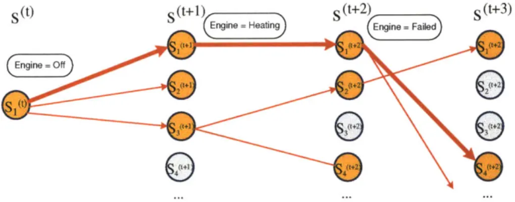
Since many failure scenarios are possible, a developer creating a model-based pro-gram for such a system would find it beneficial to be able to enumerate possible failure executions. The RMPLVerifier returns the most likely executions of a model-based program that do not lead to success. The tool tracks a set of most likely plant state trajectories over time, as shown in Figure 1-3. The figure shows a simplified trajec-tory that could be returned as a counterexample by the verifier. In this trajectrajec-tory, the engine transitions from off to heating and then to a failed state. We revisit the Mars Entry example in Chapter 5.
Sot) S(t+1) s(t+2) S(t+3)
Engine rHeatin Engine =eFailed
Figure 1-3: The Set of Plant State Trajectories Tracked by the RMPLVerifier.
1.3
The RMPLVerifier
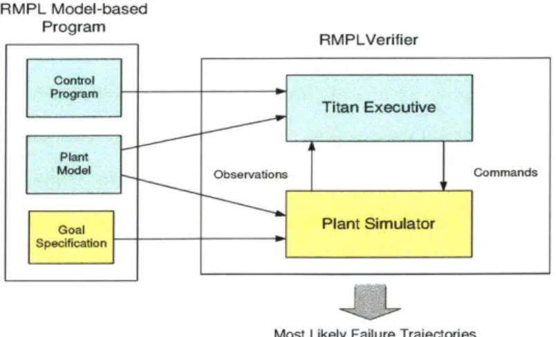
This thesis presents RMPLVerifier, a development tool for RMPL model-based pro-grams. The RMPLVerifier verifies a model-based program against a specification of success. It takes as input a model-based program with a goal specification and pro-duces as counterexamples the k most likely failure executions of the program. The verifier generates these executions by searching the space of possible trajectories using greedy forward-directed search.
The RMPLVerifier generates trajectories using Titan and a simulator that pro-vides observations consistent with the plant state. A plant state trajectory includes only states of the plant model and is tracked by the simulator. A plant state has a likelihood, computed from the likelihood of the previous state and the probability of transitioning to it from the previous state. A program state includes the states of the control program and plant estimate at a given point in the execution of a model-based program. A program state trajectory, which is generated by Titan, consists of a sequence of program states and represents the execution of a model-based program from the start state to a given time step for a given plant trajectory. The verifier returns a list of plant state trajectories. The likelihood of the plant state trajectories is used as the search heuristic. The search completes once the requested k number of solutions has been found for the given horizon. A list of trajectories, sorted in order of likelihood from highest to lowest, is returned as solutions to the verification query.
1.4
Thesis Layout
Chapter 2 of this thesis discusses related work on the verification of reactive systems. Chapter 3 defines the RMPL model-based program. It also gives background on Titan and its components. Chapter 4 defines the verification problem and presents the details of the verification algorithm. Chapter 5 introduces the Mars Entry scenario and works through a verification of the model-based program. Chapter 6 describes the implementation, and Chapter 7 gives results and conclusions.
Chapter
2
Related Work in Verification
Verification and validation (V & V) has been shown to improve software quality, yielding a number of benefits [16].
" It can detect errors early, reducing overall development cost and granting time for a comprehensive solution.
* It can evaluate the product against system requirements. For example, these may be properties required by the customer.
* It gives an incremental preview of performance of the product, allowing for early adjustments. For example, it may detect early on that a program runs too slowly for the desired application.
* It may indicate whether or not to proceed to the next development phase.
V & V is especially applicable to embedded systems that must operate in environ-ments in which they must handle a broad set of failures. Traditionally, such systems have been checked for reliability through extensive manual testing, using simulations of nominal and off-nominal scenarios. However, the number of possible scenarios can be very large for highly autonomous software, limiting the effectiveness of traditional testing [2]. This chapter gives an overview of methodologies relevant to the V & V of software for embedded systems.
2.1
Model Checking
Model checking is a methodology which exhaustively explores a system's achievable states. It is a common technique for verifying digital hardware and reactive software. Given a model of a system and a property for correctness, a model checker runs through all possible executions of that system, including interleavings of concurrent threads, and reports any execution that violates the property specification. Explicit state model checking generates and explores every state [13]. Symbolic model checking efficiently manipulates compact encodings of sets of states and, therefore, may be applied to larger systems [15]. A drawback of model checking is that the system usually is converted beforehand, into the formal syntax accepted by the model checker. This is generally a tedious process carried out manually by an expert. Alternately, translators can be used; we describe one later in this chapter [15].
Model checking has been demonstrated for verifying the correctness of plant mod-els used in model-based systems, as we see when we describe the Livingstone to SMV translator [15]. It has also proven useful for identifying bugs related to concurrency in the source code of system executives [7]. However, there are difficulties in applying model checking to verification of the executions of a model-based system, the goal of this thesis. A model-based system is difficult to translate into a formal language, a requirement for model checking. In addition, the space of executions model checking must explore is exponentially large.
We now describe applications of model checking to reactive systems.
2.1.1 Livingstone to SMV
Livingstone [21] is a model-based diagnostic system developed as part of the Remote Agent autonomous spacecraft controller [14]. Livingstone uses a plant model to de-scribe the nominal and failure modes of each component in the system. Each mode has associated modal constraints that describe the behavior of the component when in that mode. A component also has transition constraints that determine when it can switch between modes. Plant models are written in the Model Programming
24
Language (MPL). The goal of the Livingstone to SMV project was to apply formal verification techniques to the development of autonomous controllers based on Liv-ingstone. The focus was on diagnosing errors in plant models. Properties for correct models included reachability of component modes in the plant model and consistency and completeness of mode transitions. Transitions are consistent when only one of a mode's outgoing transitions to other modes is enabled at a time; two transitions can-not be simultaneously enabled. Transitions are complete when at least one transition constraint is always fulfilled.
The Livingstone to SMV translator [15 converts the plant models used by Living-stone into specifications that can be verified with the Symbolic Model Verifier (SMV)
[3], a model checker from Carnegie Mellon University. The specification for
correct-ness is expressed in terms of properties in the temporal logic CTL (Computation Tree Logic) or, alternately, using pre-defined specification patterns in MPL, Livingstone's modeling language. The translator converts both the plant model and the specifica-tion from MPL to SMV's formal language, and then converts any diagnostic output from SMV back to MPL. The translator thus saves the developer from tedious manual translation. The Livingstone to SMV translator has been used to verify properties of the Livingstone model of the Deep Space 1 spacecraft used within the Remote Agent experiment.
The Livingstone to SMV project only addressed the verification of the plant mod-els of model-based systems. This thesis seeks to verify an entire model-based program, including both control program and plant model.
2.1.2 Remote Agent
A research effort [7] was conducted that applied formal verification methods to the
RA Executive [14], one of the three subsystems of the Remote Agent autonomous spacecraft controller, demonstrated in flight on the Deep Space 1 mission. The Ex-ecutive provides operating-system level capabilities for goal-directed software. Two separate efforts applied the SPIN model checker [9] to this piece of software. The focus was to find errors in the source code of the executive.
The first effort [7] occurred during the development process and early on found five concurrency errors that would not have been found through testing. The lisp source code of the Executive was abstracted and translated by hand to the PROMELA language used by SPIN, a model checker for analyzing the correctness of finite state concurrent systems. The model checker then examined it for properties such as the liveness of concurrent tasks. The significant manual labor required motivated the creation of the Java PathFinder tool [18], a translator from Java to PROMELA. As mentioned in the next section, this tool was also later used during a V&V survey on the Rover Executive. The second effort [7] occurred due to an in-flight deadlock in a sibling subsystem to the one verified. The RA developers provided the researchers the code for the Executive without identifying where the bug was located. Researchers conducted a separate "clean-room" verification and found the concurrency error in a total process of two days; most of the time was spent in understanding and modeling the code. The project demonstrated that formal verification can find concurrency errors that occur in actual flight. It also produced tools that increased the ease with which V&V could be incorporated into the software development cycle. As one of the more successful applications of formal methods, it gave an impetus for more research in the verification of such systems.
The authors presented one of the successful applications of verification to software that was part of a reactive system. However, they focused exclusively on source code verification, the realm of traditional V&V. In this thesis we look instead at verification of the higher-level behavior of the executive, as part of the model-based system that includes the model-based program.
2.1.3 Rover Executive V & V Study
We now give an overview of a study conducted at NASA Ames for the purpose of determining the maturity of different verification and validation techniques, including model checking, on a representative example of NASA flight software [2]. The study had two goals. The first was to evaluate the relative strengths and weaknesses of traditional and advanced V&V approaches and tools on autonomy software. The
second was to determine if current tools show that advanced verification techniques are a significant improvement over traditional ones.
The study consisted of a controlled experiment where three V&V technologies (static analysis, runtime analysis and model checking) were compared to traditional testing regarding their ability to find seeded errors in the source code of a Rover executive. The Rover Executive [19] was a software prototype written in C++ by researchers at NASA Ames. It commanded a rover through the use of high-level plans. Groups of two were assigned to each methodology and given the task of finding bugs. Static analysis was conducted with the PolySpace Verifier [17], runtime analysis with the DBRover [4] and Java PathExplorer [8], and model checking with the Java PathFinder [18].
The significance of this study is that it was the first to experimentally evaluate and compare formal methods-based tools to testing on a realistic research prototype of embedded software. While the authors did not draw any strong conclusions, the study did confirm that advanced tools can outperform manual testing when trying to locate concurrency errors. They also drew a number of insights. They found runtime analysis and monitoring to be very successful in uncovering the seeded bugs. Runtime analysis methods detect the correctness of a program by collecting data from the execution of the program and then analyzing it. Runtime monitoring validates the correctness of a single execution online against a set of formally state requirements. However, as both of these techniques require the code to be executed, their effectiveness was limited to how exhaustively the test-inputs covered the input space. The authors also found model checking to be good at systematic analysis; for example, it could systematically cover all input plans up to a specific size for the rover.
This study gives basis to our claim that there is a real benefit to using automatic verification tools on reactive systems, when compared to the results obtained from manual testing.
2.2
Executable Specifications
An executable specification is a program that doubles as a specification about which one can prove properties and an executable implementation of that specification. This eliminates the need to write a specification and implementation separately [20]. We look at Esterel, a language that creates executable specifications.
Esterel [1] is a synchronous programming language. Synchronous languages were designed to program reactive systems, systems that have a reactive program as their main component. Reactive programs are programs that maintain an interaction with their environment, reacting to inputs received from the environment by sending out-puts to it. For example, an operating system driver is a reactive program embedded in a larger system. Reactive programs are composed of three layers. An interface controls input reception and output production. A reactive kernel decides what com-putation and outputs to generate in response to the inputs. A data handler performs the computations requested by the reactive kernel. Esterel is not a full programming language but a language for defining reactive kernels, which can then be generated as code in another language. It is analogous to the grammar from which a parser generator produces a parser. Once generated, the reactive kernel can be embedded in a larger program that implements the interface and data handling layers.
Esterel programs are executable specifications. The main theorem of Esterel is that the behavioral and execution semantics are equivalent. The behavioral seman-tics give a mathematical definition of the semanseman-tics of the language. The execution semantics define the actions of the underlying execution machine. Esterel is not a high-level specification language that requires the developer to rewrite the program in an implementation language once the specification is complete. Rather, the speci-fication and implementation are one and the same. Once written, a program can be efficiently compiled to object code.
RMPL is another synchronous language that builds on the ideas of Esterel. RMPL model-based programs are executable specifications that are fault-aware -they know the plant's behavior under both failure and nominal scenarios. This thesis performs
verification on RMPL executable specifications by executing them using the Titan engine.
2.3
Simulation-based Verification
Livingstone PathFinder (LPF) [12 uses a new verification approach based on simu-lation. It seeks to find diagnosis errors in the Livingstone engine, instances when the engine inaccurately diagnoses the current state of the system. LPF applies state space exploration algorithms to a testbed, consisting of the Livingstone [21] engine embed-ded in a simulated environment. The simulator is generally also a Livingstone engine. The tool runs on a Livingstone plant model and a low-level scenario of commands and injected faults. It has the ability to report error conditions during execution of the scenario on the model. It can report when the engine fails to find any consistent candidate for the current state. It can report a discrepancy between the component modes of the simulator and diagnoser. For example, if the plant model has a valve component which the simulator believes to be in the open mode and the diagnoser believes to be in the closed mode, the tool reports that there has been a misdiagnosis. LPF runs on a set of different executions defined from the permutation of the events given by the scenario. The events of the scenario are the commands and faults; the faults are interleaved in the sequence of commands. LPF explores the tree of executions given by the scenario using search, saving and restoring intermediate execution points. The user may specify the kind of search, where the options are depth-first search with backtracking, breadth-first search, or best-first search, with a heuristic that favors situations where fewer candidates for the estimated state were found and therefore a misdiagnosis is more likely to occur. The user may also specify whether to report one or all errors.
The focus of LPF is primarily on reporting diagnosis errors in the engine. A disadvantage of the tool noted by the authors was that it generated a large amount of output and could therefore benefit from improvement in the post-treatment and display of results. Currently Livingstone PathFinder only uses plant models and the
deductive controller. However, a new version, called Titan PathFinder, is currently in development. This version seeks to use Titan as the diagnostic engine, includ-ing both the deductive controller and the control sequencer; the task is still to find misdiagnoses.
LPF employs a similar strategy to the RMPLVerifier, both tools using search to explore executions of a model-based system. However, LPF focuses on finding misdiagnoses. Our tool focuses on the model-based program, finding executions of the program that do not achieve success, along with their likelihoods.
2.4
Summary
The verification research on reactive systems that we have examined has focused pri-marily on verification of those systems, while ignoring the failure behavior of the plant being controlled. In addition, in the area of model-based autonomy, verification has focused primarily on the detection of errors in the plant model or the implementa-tion of the diagnostic engine. Our focus is to develop verificaimplementa-tion approaches for an entire model-based program, which includes both a plant model and a control pro-gram. In addition, these past efforts have focused on determining the correctness of model-based systems. We instead account for uncertainty by determining how likely a program is to succeed or fail.
30
Chapter 3
The RMPL Model-based Program
Languages for embedded systems have been developed to simplify the task of control-ling devices with many different components. These languages enable one to write programs that interact with the hardware by reading sensor values and by sending commands to actuators. In programming languages like Esterel [1] and Statecharts [6], the programmer is responsible for mapping the intended state of the system to the variables holding sensor and actuator values. The complex interactions between hardware components and the large number of failure scenarios possible make this mapping error-prone. The model-based programming paradigm [20] was designed to address this problem. A model-based programming language interacts directly with the state of the plant. Programmers are given the ability to define and control hid-den state variables; by manipulating a state variable, one indirectly interacts with observable and control variables corresponding to sensors and actuators respectively. The RMPLVerifier, the central focus of this thesis, performs verification on an RMPL model-based program. In this chapter, we describe the Reactive Model-based Programming Language. Section 3.2 defines a model-based program. Section 3.1 introduces the RMPL language with the help of an example. Section 3.3 describes Titan, RMPL's execution kernel, and includes a detailed discussion of the Mode Estimation component of Titan. The details of Mode Estimation are particularly important background for verification, as the prediction step of Mode Estimation forms the core of the verifier's trajectory generation algorithm.
3.1
The Reactive Model-based Programming
Language
The Reactive Model-based Programming Language (RMPL) [20] allows developers to perform high-level reasoning on the behavior of a model. It is an object-oriented lan-guage that uses propositional state logic as its underlying constraint system. RMPL provides primitive constructs for conditional branching, preemption, iteration, and concurrent and sequential composition. We highlight the key design features of the language with the aid of an example.
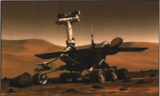
Figure 3-1: The Mars Exploration Rover. Courtesy NASA/JPL-Caltech.
A rover's mission is to drive to a final destination (Figure 3-1). In order to reach
it, it drives to a set of intermediate waypoints. It stops at each to take an image with its hazard camera, to be used by its on-board hazard avoidance algorithm. We can translate this scenario into a model-based program in the following manner.
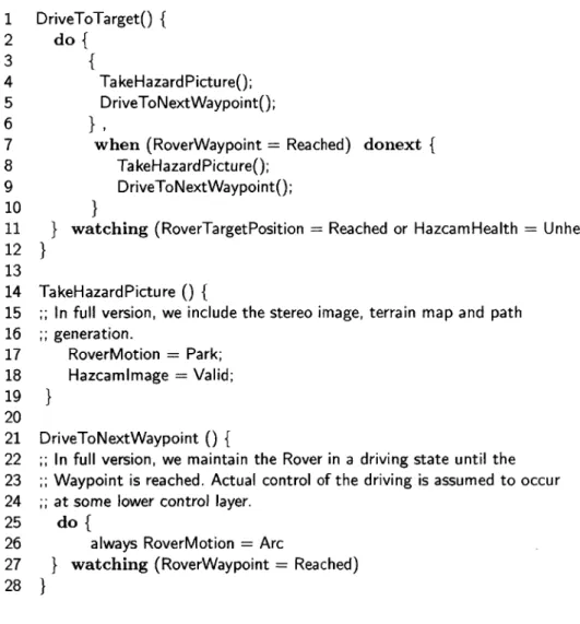
Figure 3-2 shows the RMPL control program. It is expressed in a style similar to traditional software programs. In the main procedure, DriveToTarget(, the rover initially takes a picture with the TakeHazardPicture() subprocedure and drives to the next waypoint with the DriveToNextWaypoint( subprocedure. When it has
1 DriveToTarget() { 2 do{ 3 { 4 TakeHazardPictureO; 5 DriveToNextWaypointO; 6 } ,
7 when (RoverWaypoint = Reached) donext {
8 TakeHazardPictureO;
9 DriveToNextWaypointO;
10 }
11 } watching (RoverTargetPosition = Reached or HazcamHealth = Unhealthy) 12 }
13
14 TakeHazardPicture () {
15 ;; In full version, we include the stereo image, terrain map and path 16 ;; generation. 17 RoverMotion = Park; 18 Hazcamlmage = Valid; 19 } 20 21 DriveToNextWaypoint 0 {
22 ;; In full version, we maintain the Rover in a driving state until the 23 ;; Waypoint is reached. Actual control of the driving is assumed to occur 24 ;; at some lower control layer.
25 do {
26 always RoverMotion = Arc
27 } watching (RoverWaypoint = Reached) 28 }
Figure 3-2: A Control Program for the Rover-Hazcam Scenario.
reached this waypoint, it repeats its actions. In this way, the rover drives to each intermediate waypoint, stopping to take a hazard picture at each before proceeding.
If, at any point, it reaches its target position or detects that the state of the camera
is unhealthy, the procedure terminates.
This example highlights several important properties of a control program. First, the code is written in terms of state assignments. Assignments may be used as execu-tion condiexecu-tions. The assignment RoverTargetPosiexecu-tion = Reached is an execution
condition that depends on the plant's hidden state variable RoverTargetPosition (Line 11). State assignments may also be used as assertions. The assignment
Rover-Motion = Park (Line 17) in the TakeHazardPicture() procedure directs the system to make that assertion true once execution reaches that point in the program. These hidden state assignments are not directly observable or controllable. They pro-vide a layer of abstraction that makes it easier for the developer to write a reactive program. This specification is far simpler than a program that must turn on motors and switches directly. Second, RMPL allows both parallel execution, denoted by a comma, (Line 6) and sequential execution, denoted by a semicolon (Line 5). RMPL also allows both conditional execution and iteration. The when ... donext con-struct on Line 7 is an example of both; the actions inside the concon-struct repeat until the condition, RoverWaypoint = Reached, is satisfied. Finally, the language al-lows preemption. The procedure DriveToTarget( terminates if either RoverTar-getPosition = Reached or HazcamHealth = Unhealthy becomes true (Line
11).
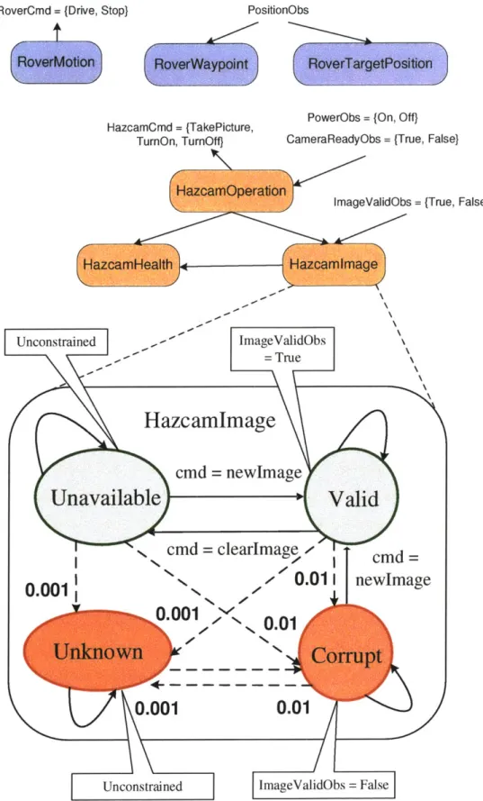
The plant model is a representation of the rover's behavior, and is used by the Titan executive to achieve the control program. It is a system composed of several subcomponents, each illustrated by a rectangle in Figure 3-3. These components in-teract with the hardware through sensor and actuator values. They may also inin-teract with each other. The figure uses arrows to show incoming observations and outgo-ing commands, as well as the flow of internal information between components. The RoverMotion component describes the movement of the rover; it can command it to drive or stop. The RoverWaypoint and RoverTargetPosition components check to see if the rover has reached a waypoint and its target destination respectively; they receive position information as observations. The HazcamOperation, HazcamHealth, and Hazcamlmage components represent the Hazcam camera of the rover. Hazcam-Operation can command the camera to turn on or off or to take a picture. It can observe whether the power is on or off and whether the camera is ready. Hazcamlm-age can observe whether the imHazcamlm-age recorded is valid; it depends on input from Haz-camOperation. HazcamHealth decides whether the camera is in healthy condition, depending on inputs from HazcamOperation and HazcamImage. The plant model given for this example scenario is still somewhat high-level. A model to be used
34
S111_1E111 ~~iii~iJjiLLIL iiiii.imuim El Q ________
RoverCmd = (Drive, Stop) PositionObs
HazcamCmd = (TakePicture,
TurnOn, TurnOff)
PowerObs = (On, Off)
CameraReadyObs = {True, False)
ImageValidObs = (True, False)
ed '' ImageValidObs True
Hazcamlmage
cmd = newhmageavailable
Valid
cmd
= clearlmage cmd0.011
newImage
in001
0.01
Uncon.01
0.01
strained ImageValid~bs = False
Figure 3-3: The Plant Model for the Rover-Hazan Scenario. Unconstrain
Un
in a real scenario would contain many more low-level components that describe the hardware more accurately.
Each component is defined separately in terms of the nominal and failure states it may occupy. Since components may be defined independently, it is simple to build a plant model in a modular manner by reusing components. A component's state depends on the actual observations received and commands issued to the hardware. We look in detail at the component definition of Hazcamlmage, the graphical rep-resentation of which is shown in Figure 3-3. HazcamIlmage represents the hidden state of the camera image. It has the nominal modes Valid and Unavailable and the failure modes Corrupt and Unknown, corresponding to the states that it may occupy. It observes the validity of the image from the plant as sensor readings True or False. When the image is Valid, we expect the observed output to be True, and when the image is Corrupt, we expect it to be False. Each mode in the figure is labeled with a modal constraint that expresses these conditions. For example, mode Valid has ImageValidObs = True. The Unknown mode is unconstrained, since nothing is known about the conditions of an unanticipated failure. The Unavailable mode is also unconstrained, since no image is available at that point for observa-tion. The figure illustrates the commanded transitions between Unavailable, Valid and Corrupt. The command newlmage transitions the state to Valid, and the command clearImage transitions it to Unavailable. This particular model defines relationships such that Hazcamlmage's commands are variables dependent on the out-put of HazcamOperation. However, a component may command the plant directly in the same manner. One may also take an un-commanded transition to the fault modes Corrupt and Unknown from any other mode. This indicates that the image may fail at any time. Self-transitions indicate that the state of the image has not changed between time steps. Each transition between states has a probability; only the fault transitions are labeled in the figure. For instance, upon issuing the command newlmage when the image is unavailable, one has probability 0.001 of transitioning to Unknown, probability 0.01 of transitioning to Corrupt, and probability 0.989 of transitioning successfully to Valid.
As we have seen, the control program combined with the plant model compose the complete RMPL model-based program. The RMPL compiler efficiently compiles the components of a model-based program into representations of finite automata. A plant model is represented by a Concurrent Constraint Automaton (CCA) [20]. A CCA is a composition of concurrently operating constraint automata, along with the interconnections between component automata and with the environment. A control program is represented by a Hierarchical Constraint Automaton (HCA), a variant of hierarchical automata [20]. The plant model and control program are defined in the next section.
3.2
The Model-based Program
A model-based program enables one to specify the desired state evolutions of the embedded system. It consists of a control program and a plant model. The plant model is a representation of the hardware, defining its nominal behavior and its behavior during common failures. The control program specifies the system behavior in terms of the model. The verifier returns plant state trajectories that are expressed using the variables of the plant model.
The plant model defines state variables in terms of control and observable vari-ables, and the control program sets these state variables. We give the formal def-initions of each below. The plant model is a partially observable Markov decision process P = (1, E, T, Pe, PT, Po, R), where:
* H is a set of finite-domain variables, divided into state variables TlS, control
variables flC, and observable variables Ho. A state of the plant is defined as an assignment to H. Control and observable variables correspond respectively to commands issued to and observations received from the actual plant.
* E is the set of all feasible full assignments over H. An assignment is feasible if it is allowed by the constraints inherent to the hardware. The set E, the projection of E on variables in 1I', is the set of all feasible states.
" T is a finite set of transitions. A transition T E T is a function T : E - E, that
maps feasible full assignments over H to states.
" Pe(so) is the probability that the plant has initial state so.
* PT(T) is the probability associated with transition function r.
* Po(si, oj) is the probability of observing oj in state si.
" R(si) is the reward for being in state si.
The control program is a deterministic automaton CP = (Ec, ec,,p Tp, ge,, E,),
where:
" EC, is the set of program locations. A program location is defined as the state of the control program.
" (),P is the initial location.
" Tc,, is the transition function between locations, conditioned on plant states of P. In other words, eT : EXP x E, --+ EcP.
* gc,(l) is the configuration goal of location 1. Each program location has a
con-figuration goal, which is the set of legal plant goal states associated with that location.
* E, is the set of all feasible states of the plant model.
One executes a model-based program by generating a control sequence that moves the plant to the states, known as configuration goals, specified by the program. A
model-based executive executes a program by continuously generating these
configura-tion goals based on the plant model and the current plant state. A configuraconfigura-tion goal is translated to commands that are sent to the plant. The executive also continually estimates the current plant state based on the plant model and sensor data. The executive uses this information to determine if goals were successfully achieved and to diagnose failures.
3.3
Titan
Titan [20] is the model-based executive for RMPL. The architecture for Titan is shown in Figure 3-4. Titan has two main components, the control sequencer and the
deductive controller. The control sequencer generates the configuration goals, based
on knowledge of the state of the control program and the estimated state of the plant model. The deductive controller has two subcomponents, mode estimation and mode reconfiguration. Mode Estimation (ME) generates an estimate of the plant's most likely current state, based on observations received from the plant and commands issued to it. Mode Reconfiguration (MR) sends commands to the plant that progress the plant through the states necessary to achieve the configuration goals.
Titan RMPL
Control Control Sequencer
Program
State estimates Configuration goals
Plant _Deductive Controller
Model
_1
ME MR
Observations Commands
Plant
Figure 3-4: The Architecture of the Titan Model-based Executive.
3.3.1
Mode Estimation
A plant state trajectory is a sequence of feasible states. The space of possible state
trajectories can be visualized through a Trellis diagram, shown in Figure 3-5(a). The
Trellis diagram. enumerates all possible states at each time step and all transitions
between states at adjacent times. Mode Estimation (ME) is an online algorithm for
77;_-tracking the most likely states through this diagram that are consistent with the plant model, the observations and the commands. ME is an instance of Hidden Markov Model belief state update. Belief state update associates a probability to each state in the Trellis diagram. ME selects the tracked state with the highest probability as the most likely state estimate. Belief state update computes the current belief state, the probability of being in each state sj at time t + 1, with the following equations:
01~~ ) S(t) Zo+ [SilPT(O'i) 8j)
Uft+1.) [sy] = 07.(0 Js E n Po+ sy[,]pon)
i=IOk
Z2=
out+1) [si]Pn(si, Ok)PT(O-i, s) is defined as the probability that the plant P transitions from full as-signment o-i to state sj, computed as the sum of P, over all transition functions T
that map c- to s. The a priori probability o@t+s) [] is conditioned on all observa-tions up to o(t) The posteriori probability u(t+1.) [s,] is also conditioned on the latest observation o(t+) = O.
3.3.2 k Best Trajectories Mode Estimation
Ideally we would like mode estimation to track all possible states of the system for all time in order to compute the most accurate estimate of the current state. How-ever, this is very costly in practice, so ME uses approximate belief state update [10] instead. Rather than tracking the true belief state, ME computes the set of states reachable by the most likely transitions, given the latest commands and observations
(Figure 3-5(b)). This approach has the limitation that a low-probability trajectory that is pruned may become very likely at a later time, after considering additional information. Since ME no longer tracks the true belief state, we cannot guarantee that the true current state is included in the set of tracked current states. An addi-tional limitation of this approach is that it does not add the posterior probabilities for multiple separate trajectories that lead to the same state; instead, only the most likely of these trajectories is chosen. Therefore, the resulting probability of the target
(a)
current next future
(b)---current next future
Figure 3-5: (a) A Trellis diagram showing all possible state trajectories. (b) k Best Trajectories Mode Estimation tracks only the most likely states.
state is an underestimate of the true probability of being in that state.
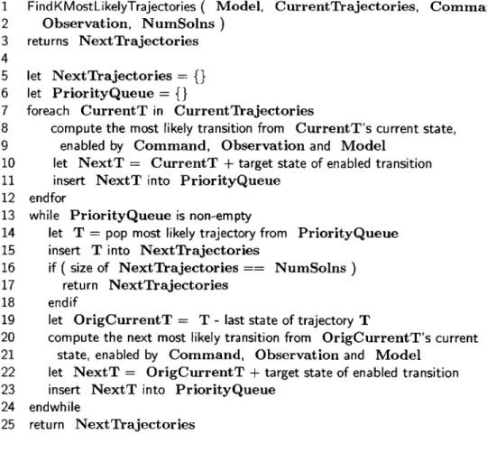
Figure 3-6 gives the pseudocode for the k Most Likely Trajectories algorithm [20] currently used by Titan's Mode Estimation. We begin with the set of current most likely trajectories, as well as the new command and observation received by Mode Estimation from Mode Reconfiguration and the plant respectively (Lines 1-2). A trajectory is a sequence of estimated states. For each current trajectory, we first find the most likely transition to the next state, enabled by the model and this new information (Line 8). We create a new trajectory by appending this state to the end of the current trajectory and add it to a priority queue, ordered by the trajectory probability (Line 10-11). Next, while the priority queue is not empty, we get the most likely trajectory in it and add it to the list of next trajectories (Line 14-15). If we have found k trajectories, we exit at this point (Line 16-17). If not, we find the current trajectory that originated it; this is the trajectory after its last target state
-1 FindKMostLikelyTrajectories ( Model, CurrentTrajectories, Command, 2 Observation, NumSolns) 3 returns NextTrajectories 4 5 let NextTrajectories = {} 6 let PriorityQueue = {}
7 foreach CurrentT in CurrentTrajectories
8 compute the most likely transition from CurrentT's current state,
9 enabled by Command, Observation and Model
10 let NextT = CurrentT + target state of enabled transition
11 insert NextT into PriorityQueue 12 endfor
13 while PriorityQueue is non-empty
14 let T = pop most likely trajectory from PriorityQueue
15 insert T into NextTrajectories
16 if ( size of Next Trajectories == NumSolns)
17 return NextTrajectories
18 endif
19 let OrigCurrentT = T - last state of trajectory T
20 compute the next most likely transition from OrigCurrentT's current 21 state, enabled by Command, Observation and Model
22 let NextT = OrigCurrentT + target state of enabled transition
23 insert NextT into PriorityQueue 24 endwhile
25 return NextTrajectories
Figure 3-6: The k Most Likely Trajectories Algorithm.
has been removed (Line 19). We create another new trajectory, based on the next most likely enabled transition (Line 20-22). We add it to the priority queue (Line
23). This ensures that the final set of k next trajectories is the most likely, based
on the possible trajectories from all currently tracked trajectories. If more than k trajectories are possible, these are pruned automatically as they are never inserted into the list of next trajectories.
Chapter 4
The Verification Algorithm
The RMPLVerifier is a tool for offline verification of RMPL model-based programs
- both plant models and control programs - for the Titan executive. RMPLVerifier searches the space of state trajectories of the model-based program using greedy, forward-directed, best-first search. It attempts to return the k most likely program failure trajectories for a bounded time period.
In this chapter, we describe the verification problem and algorithm. Section 4.1 defines the problem we wish to solve. Section 4.2 gives an overview of the verification process. Section 4.3 gives an overview of the algorithm. Section 4.4 gives the top-level pseudocode of the verifier. Section 4.5 gives the pseudocode for the simulator component and describes the modified k Most Likely Trajectories algorithm it uses to track the most likely plant trajectories.
4.1
Problem Statement
We seek to answer the verification question "What are the k most likely plant trajec-tories that do not achieve a given goal within N time steps, given the control program, plant model, and starting configuration of an RMPL model-based program?"
Successful execution of a model-based program can be defined as achievement of its stated purpose, whether this is taking a picture with a camera or controlling the navigation of a satellite. Conversely, failure can be defined as not achieving this