Blending Engineering Modeling, Industrial Design,
and Physical Prototyping in Product Design
by
Matthew E. Page
Bachelor of Science in Mechanical Engineering Cornell University, 1998
Bachelor of the Arts in Physics Ithaca College, 1998
Submitted to the department of mechanical engineering in partial fulfillment of the requirements for the degree of
Master of Science at the
Massachusetts Institute Of Technology June 2000
© 2000 Massachusetts Institute of Technology. All rights reserved.
Signature of Author: ...
C ertified by: ...
Acce ted b :
... ... ...
Department of Mechanical Engineering Mov 5. 2000
Woodie C. Flowers Pappalardo Professor of Mechanical Engineering Thesis Supervisor
y .J... ...
Ain A. Sonin MASSACHUSETTS INSTITUTE Professor of Mechanical Engineering
OF TECHNOLOGY Chairman, Department Committee on Graduate Students
SEP
2 0
2000
Blending Engineering Modeling, Industrial Design,
and Physical Prototyping in Product Design
by
Matthew E. Page
Submitted to the Department of Mechanical Engineering on May 5, 2000 in partial fulfillment of the requirements for the degree of
Master of Science
Abstract
Engineering simulation models, industrial design form models, and physical experimentation through prototypes are critical elements of successful product design. However, the three disciplines are disconnected and the direction of simulations, form models, and physical prototypes often diverge increasingly as product detail is developed. This divergence often results in an expensive and time consuming design cycle and inferior product quality. The first 10% of the cycle is taken up largely by conceptual design, an iterative stage that requires close interaction between industrial designers, modelers and engineers. In the current state of the art, information is often lost when models are approximately reconstructed from physical prototypes, CAD or surface models.
A new approach to the conceptual design cycle is developed and applications for the design of consumer products are discussed. The tools that make up the cycle work together to create a flexible, iterative design environment. Industrial designers, engineers, and modelers generate and exchange form concepts, alternating between physical and digital representations of product geometry. Rapid alternation between the physical and digital domain is enabled and information flow between iterations is improved.
Thesis Supervisor: Woodie C. Flowers
Acknowledgements
Professors Woodie Flowers and David Wallace are gratefully acknowledged for their advice, patience, and clarity whenever I forgot what I was doing.
I would like to thank the Center for Innovation in Product Development and the National Science Foundation for sponsoring this work. This research is supported in part by the by the MIT Center for Innovation in Product Development under NSF Cooperative Agreement Number EEC-9529140.
In addition, the following people are respectfully acknowledged:
* My parents for encouragement and space to always choose my own path, even if sometimes I had to be nudged out of the woods.
* My brother Jamie for making it possible to win part of the $50k with a sporting product, and for the incredible motivation he gave me to graduate.
* All of my friends for their incredible advice and support.
* BOSE for all the help and information I could have asked for and more. * Steven Silverstein for his selfless donation of time and effort.
* Patrick Timony for the models and terrific conversations.
* The Product Design Firms who gave generously of their time (listed alphabetically):
Altitude (ELEVEN) Manta Product Development
Bleck Design Group Fitch Product Genesis
Carroll Design Insight Product Development Product Insight
Design Continuum Inc. IC3D Radius Product Development
Designturn IDEO
* Ben and Julie for their patience and advice in my first year.
* John and Tom for their mutual support, candy, and baked goods. What an office!
* Stephen Smyth and the inmates of the CADLab for letting me keep the best machine all to myself (except for Quake, of course).
* The CIPD for being a place full of food and ideas.
* Jim Bredt and Z Corporation for their enthusiasm and for building the machine that made the pretty things that I chopped up (.
Table of Contents
Abstract ... 3 Acknowledgements ... 5 Table of Contents ... 7 List of Figures ... 9 List of Tables ... I I Chapter I ... 13 Introduction ... 13 1. 1 M otivation ... 13 1.2 Thesis Organization ... 131.3 Conceptual Design Cycle ... 14
1.4 Background ... 15
1.4.1 The Center for Innovation in Product Developm ent (CIPD) ... 15
1.4.2 Related W ork ... 16
Chapter 2 ... 20
Conceptual Design ... 20
2.1 Definition of Conceptual Design ... 20
2.2 Conceptual Design Practice ... 21
2.3 Design Cycle Concept ... 23
Chapter 3 ... 26
Components and Integration ... 26
3.1 Components ... 26
3. 1.1 Computer Aided Design (CAD) ... 26
3.1.2 Digitizing Form M odels ... 29
3.1.3 Rapid Prototyping ... 32
3.1.4 M odeling M aterials and Tools ... 36
3.21ntegration ... 41
Chapter 4 ... 45
Applications ... 45
4.1 Form Design and Iteration ... 45
4.1.1 Ergonom ic Form Design ... 45
4.1.2 Component Layout ... 48
4.1.3 Form Exploration for Aesthetic Design ... 49
4.2 Product Design Education ... 54
Chapter 5 ... 57
Conclusions and Future Directions... 57
5.1 Conclusions ... 57
5.2 Future W ork ... 58
5.2.1 Integration W ith Other Research ... 58
5.2.2 Software ... 59
5.2.3 Hardware and M aterials... 60
References and Notes... 63
Appendix 1... 65
Com pany Contact Information ... 65
Appendix 2... 69
List of Figures
Figure 1.1 D esign Cycle Concept ... 14
Figure 1.2 Form Synthesis Concept ... 18
Figure 1.3 D esign Cycle Proposed in 1996 ... 18
Figure 2.1 The Product Development Process... 21
Figure 2.2 Design Cycle Proposed in 1996 ... 24
Figure 2.3 (a-h) The Integrated Conceptual Design Cycle ... 25
Figure 3.1 Common Sketch Modeling Materials ... 38
Figure 3.2 Common Visual Modeling Materials... 39
Figure 3.3 Carving a 3D Printed Model ... 40
Figure 3.4 The Integrated Conceptual Design Cycle With Components ... 41
Figure 3.5 Workstation With PHANToM7M and Models... 42
Figure 3.6 Steinbichler Comet 250 Scanner, Turntable and Models... 42
Figure 3.7 The Z Corporation Z402 Printer and Software Interface... 43
Figure 3.8 Editing a Model With the FreeForm Digital Clay Application... 43
Figure 4.1 Ergonomic Handle Prototype ... 45
Figure 4.2 Digitized Handle in STL Format ... 46
Figure 4.3 H andle Variations... 46
Figure 4.4 Timeline For Modifying the Handle With the New Cycle ... 47
Figure 4.5 Iges Files Created from Scan Data ... 47
Figure 4.6 M ono Radio Components ... 48
Figure 4.7 Component Underlay Within a Surface Model ... 49
Figure 4.8 3D Underlay: CAD Model, STL File, and 3D Print... 49
Figure 4.9 Form Exploration Using a Physical Underlay ... 50
Figure 4.10 Mono Radio Forms
from a 3D Underlay ...
50Figure 4.11 Digitization and Reproduction of a Selected Radio Concept ... 51
Figure 4.12 Form Design Based on a Digital 3D Underlay from CAD ... 52
Figure 4.13 Form Design Ready
fr
Rapid Prototyping... 52Figure 4.14 Exploring Form in Rhino... 53
Figure 4.15 Simple Geometric Form Template... 53
Figure 4.17 Visual M odel in Progress ... 54
Figure 4.18 Finished Visual Models
for
2.744... 55Figure 4.19 Finished Urethane Model with Freeform Surfaces ... 55 Figure 5.1 Integrated View of the Conceptual Design Cycle, Form Synthesis Engine,
and D O M E ... 52 Figure 5.2 Cracked 3D Printed Part (ZP 1I Powder and ZB7 Binder) ... 61
List of Tables
Table 3.1 Popular 2D Design Software ... 26
Table 3.2 Popular 3D CAD Software ... 27
Table 3.3 Automated Digitization Techniques ... 30
Table 3.4 Common Methods Jbr Rapid Prototyping and Tooling... 33
Chapter 1
Introduction
1.1 Motivation
There is a tremendous need for the development of conceptual design tools that both suggest and allow the intuitive manipulation of product form. This thesis presents a system that allows rapid alternation between physical and digital representations of product geometry.
Engineering simulation, industrial design, and physical experimentation through prototypes are critical elements of successful product design. However, as the product detail is developed, the three disciplines become disconnected. Specifically, the direction of simulations, form models, and physical prototypes diverge. The design process becomes expensive, frustrating, and time consuming. "An ill or poorly conceived design concept cannot be easily compensated for at the later stages of the design process or during production, or even via marketing policies." [Sharpe
1994].
The first 10% of the product design process is taken up largely by conceptual design, an iterative stage that requires close interaction between industrial designers, model makers, and engineers. This initial stage in development sets the direction for approximately 80% of the resources necessary to design a product [Sharpe 1994]. While enormous advances have been made in computer representations of product geometry, physical prototypes remain the most intuitive and trusted representation for evaluation and editing. The goal is to enable designers to effectively and efficiently use physical models in the context of a digital product development process. In the current state of the art, when information is transferred among the various types of models, time and information are lost. Creating a more direct connection among the three types of models will improve the accuracy and speed of iteration within the conceptual design cycle.
1.2 Thesis Organization
This thesis presents an approach to form development that is ready for use in product design practice, and is fertile ground for further research. The following chapters describe the
conceptual design stage of product development, and present a framework for use of the form design cycle within this stage. The benchmarking, acquisition, and integration of hardware and software is explained, and applications are presented and discussed. The results of selected applications are shown, and conclusions and suggestions for improvement and future work are presented.
Chapter 2 presents a definition of conceptual design and the proposed design cycle is described in the context of modem practice.
Chapter 3 covers the selection and integration of components for the new design cycle. A brief overview of each area is given.
Chapter 4 discusses applications for the conceptual design cycle through examples. Chapter 5 offers the conclusions of the research, and makes recommendations for further development.
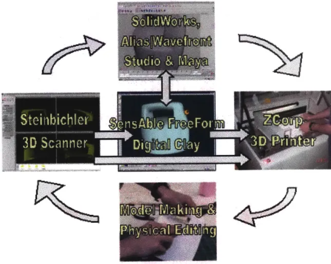
1.3 Conceptual Design Cycle
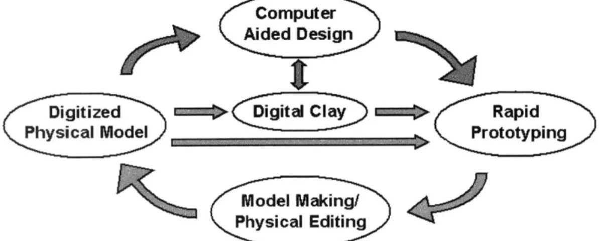
This thesis presents a system that allows rapid alternation between physical and digital representations of product geometry as shown in Figure 1.1.
Computer Aided Design
Digitized N ~gtl l~ =o Rapid
Pyial Mode ;) ______________ Prototyping
Model Making/ Physical Editing
Figure 1.1 Design Cycle Concept
The system is an iterative cycle for form exploration and refinement during the conceptual design phase of product development. The exchange between physical and digital models allows the designer to exploit the strengths of both mediums. Designers and engineers leverage the
physically intuitive geometry. More concepts can be explored, and communication of intent is facilitated. Some of the many applications for the cycle are listed below.
1. Workflow flexibility: design in any medium
2. Improved communication of intent: 2D drawings, 3D CAD, or physical mock-up
3. Physical evaluation and modification linked to a digital database (capture models that look or feel "just right")
4. Link to other research topics such as Computer-Aided-Industrial-Design (CAID) [Smyth 2000] tools and DOME (Distributed Object-Based Modeling Environment) [1]
5. Incremental model changes
6. Physical form variations from rapid prototypes of a digital or physical master (physical underlay, scaling models, 3D copier)
7. Obtain direct customer and client feedback with a combination of media 8. 3D fax machine (recipient of the "fax" must have rapid prototyping capability) 9. Toy design
10. "Smart Scanning": digital capture and incorporation of physical design changes without re-digitizing the entire object
11. Ergonomics and human factors
12. Countless medical applications, including reconstructive surgery and prosthetics 13. Computer graphics linked to physical models for rendering and entertainment 14. Sculpture
15. Architectural design
1.4 Background
1.4.1 The Center for Innovation in Product Development (CIPD)
The Center for Innovation in Product Development is a National Science Foundation
Engineering Research Center. The CIPD supports an interdisciplinary program between MIT's School of Engineering and Sloan School of Management. Center research seeks to provide the new knowledge, engage in pilot tests of the new tools and methods, and develop the foundation for commercial products and services that enhance an organization's product development capabilities [2].
To develop successful new products, an organization first must identify market opportunities that align with its capabilities. Then, it must find the best ways to develop, deliver, and service the
new products. Organizational structure, policies, and incentive structures can either inhibit or support the development of new products. Finally, any necessary changes in production and management, as well as knowledge accumulated during the process, must be maintained and distributed throughout the organization. These process requirements are reflected in the Center's four research thrust areas:
1. Product Portfolio Definition
2. Information-Based Product Development 3. Enterprise Strategy
4. Effective Enterprise Learning.
This thesis advances the Thrust 2 objectives by adding new capability to existing design tools through system integration. The system is ready for integration with two other research projects at MIT. The first related project is a non-CIPD effort in Computer-Aided-Industrial-Design (CAID) sponsored by Ford Motor Co. The second is a large CIPD research project called DOME (Distributed Object-based Modeling Environment) [1]. Both projects are based in MIT's
Computer-Aided-Design Lab [3]. The research presented here, coupled with the CAID project, advances the CIPD's vision by extending the application of DOME into the realms of rapid prototyping and industrial design.
1.4.2 Related Work
Extensive research has been conducted on the product design process and related tools. The following section highlights some past and current research into related fields.
Delft University of Technology researchers are developing new computer-aided-conceptual-design tools. They are looking into using speech, gestures, and reverse engineering (3D scanning) to generate a vague shape that will become the intended form [Horvath, Vergeest, Rusak, and Kooijman 1999]. Research is also being done at TU Delft on the application of editable physical concept models in industrial design. A new method of rapid prototyping and editing called free-form thick layered object manufacturing (TLOM) is being developed. FF-TLOM would allow material addition as well as subtraction [Horvath, Vergeest, Rusaik, and Broek 1999].
Other research investigated the role of prototyping within mechanical and electro-mechanical product design. Guidelines were proposed for choosing prototyping and fabrication solutions, and future process development needs are presented. The technologies evaluated included CAD, CNC machining, stereolithography (SLA), and rubber molding (RM -also known as RTV molding) [Wall 1991].
A computer aided industrial design tool was developed at MIT in 1991 to assist in the automatic styling of mass produced consumer products. The user selects components to be included in the product, and the system automatically creates component configurations, a housing, and applies styling to details such as buttons and speaker grilles, and colors the product. One strength of the system is its ability to generate multiple design alternatives for a product concept [Wallace
1991].
Another The European research group (Brite-EuRam Project No. BE96-3579) known as FIORES (Formalization and Integration of an Optimized Reverse Engineering Styling Workflow) consists of 12 partners including automotive and styling companies, system suppliers, and research institutes [4]. They are working to optimize the styling workflow by formalizing evaluation criteria "for aesthetic surfaces which can then be used directly for modifying free-form surfaces in the sense of target driven design or Engineering in Reverse (EiR)" [Dankwort 2000]. This program emphasizes styling as a major point of product differentiation in the modem
marketplace, "since their functionality and quality have more and more adjusted to one another
-also at an international level - and are thus taken for granted by the customer" [Dankwort 2000]. The FIORES website contains more background information and several papers in Adobe PDF
format [4].
Research has also been done toward the goal of automatic generation of designs from shape grammars and fabrication with rapid prototyping. Rapid prototyping is used to create physical models for two reasons. First, our understanding of a model is often limited by the 2D computer
screen, even with today's high quality computer graphics capabilities. Second, it is often faster to use rapid prototyping methods than to hand-make even simple geometries [Wang 2000].
Two research projects at MIT relate directly to this work. The first project (mentioned in section 1.2.1) deals with an area of computer aided industrial design (CAID) called Form Synthesis. In the envisioned system, industrial designers begin by defining topology archetypes and
characteristic form elements desired in the product. Then, engineers detail the design and the ID system responds with alterations using aesthetic, ergonomic, and manufacturing principles in combination with the industrial design archetypes to automatically generate styled design alternatives. These alternatives could even be used to obtain customer feedback. At various checkpoints in the process, industrial designers can also choose to electronically or manually edit the forms that were automatically generated by the ID system [Smyth 2000]. Figure 1.2 shows Smyth's example of instrument panel (IP) design using the envisioned Form Synthesis Engine.
Form Synthesis ____________Engine
IP design intent IP concept
Brand Styling Human Factors Functional & Mfg. Basic Platform
Guidelines Constraints Constraints Geometry
Figure 1.2 Form Synthesis Concept [Smyth 2000]
The second related topic deals with the integration of rapid prototyping and reverse engineering for complex 3D shape design. A design cycle was created which allowed engineers and
designers to move between electronic and physical models of a product through 3D printing and deconstructive digitizing techniques (Figure 1.3).
Rapid
Prototyping
Computer Aided
Edit Physical
Design
Model
Digitize Physical4
Model
Figure 1.3 Design Cycle Proposed in 1996 [Robinson 1996]
This work focused on the development of suitable rapid prototyping and reverse engineering techniques and provided a proof-of-concept design cycle in a laboratory setting. [Robinson
1996]. Robinson's thesis provides the base for the current research, in which the system in Figure 1.1 is formed from commercially available technology and tested.
Chapter 2
Conceptual Design
This thesis is an exploration of a new approach to conceptual design. In order to understand the utility of the proposed design cycle, it is helpful to understand current trends in design practice. Section 2.1 presents a definition of conceptual design in context of the product design process. Section 2.2 covers the proposed design cycle in the context of modern conceptual design. Section 2.3 explains the approach to conceptual design taken in this thesis.
2.1 Definition of Conceptual Design
In this thesis, the term conceptual design refers to the preliminary stages of design, where the basic functional requirements are specified, and forms that govern the look and feel of a product are established. At the beginning of this stage, a project plan is created, and engineering,
industrial design, and manufacturing set the direction of the project by eliminating as many concepts as possible. This thesis focuses on the interaction of industrial designers, engineers, and model makers (if the company in question has dedicated model making staff) during this stage.
Industrial design encompasses the design of everyday products intended for the mass consumer
market [Wallace 1991]. The main objective of the industrial design process is to give form to a product through human factors, aesthetics, styling and manufacturing guidelines. A great deal of creativity is necessary to create a balanced design. The resulting form, or seen surface of a product, becomes the product's identity in the eyes of the consumer. Designers often begin the form exploration process with constraints in the form of basic components, corporate identity (styling), and available manufacturing processes. Ideas take shape in 2D and/or 3D, digital and/or physical forms, whichever medium best conveys the designer's intent. The late Sir Misha Black quotes R.E.D. Bishop on the standards expected of an industrial designer [Black 1983]: "The conflicting standards of perfection that a designer may be asked to aim at are those of infinite life, no cost, no mass, no size, extreme beauty, no time to design or make."
Engineering in product development is the technical cousin of industrial design. Engineers create
designers work on the exterior of a product to satisfy human needs that are often irrational, engineers focus on the functional requirements of a product. Parts must fit and work together. They should be strong enough to hold up to their intended use. Engineering and Design are different cultures, which can make linking them difficult. However, there are two fundamental ideas that are clear across both disciplines [Holmes 1995]:
" There is no infallibly good method of designing products. * No specified sequence of operations can guarantee a result.
Some companies have dedicated model makers, generally expert machinists or industrial designers with an exceptional flare for physical modeling. In many organizations, industriual designers and engineers make their own concept models and benchtop prototypes. Other
companies outsource their physical modeling to model making specialists, machine shops, or use rapid prototyping instead of hand made or machined models.
2.2 Conceptual Design Practice
Different companies divide the product design process into stages in different ways, but the underlying structure of the process is similar. Figure 2.1 presents a general overview of product development. This Figure is derived from Ulrich and Eppinger [1995]. Conceptual design falls within the bounds of Phase I. Conceptualization sets the direction of the rest of the design process. According to Ulrich and Eppinger, "a product concept is an approximate description of the technology, working principles, and form of the product" [Ulrich 1995]. A concept may be communicated through a sketch, rendering, rough three-dimensional model, or combination thereof (any of these forms may be either hand-made or done in software). Concepts are often accompanied by a brief textual description to help communicate intent.
Phase I Phase II Phase III Phase IV Phase V
Concept System-Level Detail Testing and Production Development Design Design Refinement Ramp-Up
Figure 2.1 The Product Development Process [Ulrich 1995]
By Phase II, the team should be confident that the design space that surrounds a product has been
enough for the product to be considered from a more technical standpoint. This is not to say that the design will not change after this point, but that if a good concept has been selected, changes are mainly to the details of the product rather than to gross form or layout. Phases III through V are not detailed here because they are beyond the scope of this thesis.
In order to better understand conceptual design in industry today, two sets of interviews were held with 15 Boston-area product design companies, professional model makers, and
manufacturing companies (see Appendix 1 for a list of company contact information). The first set of interviews were conducted by two senior undergraduate students at MIT. They obtained qualitative and quantitative data about company structure and the approach to product design taken by Boston-area product development companies [Liu and How 2000]. The data from these interviews is not explicitly presented here, but is the basis for the current methods and tools listed here and in later sections. The second set of interviews were informal, and focused on current conceptual design methods and opportunities for improvement. The invitation to participate in both interviews was a single letter which can be found in Appendix 2.
The interviews revealed that industrial designers and engineers in the concept generation stage pass models back and forth to evaluate ideas on a variety of levels. The product is considered from the standpoint of the user as well as the manufacturer. Areas of primary interest generally include ergonomics, aesthetics, style, component layout, and opportunity for innovation. In order to convey design intent, data is transferred between various media, such as:
" 2D hand sketches and renderings " 2D CAD layouts and renderings
Vellum, AutoCAD, Adobe Photoshop and Illustrator * 3D CAD surface models and solid models
AliasIWavefront, Pro/ENGINEER, Pro/Designer, Rhino, SolidWorks, SDRC IDEAS
" physical prototypes
hand-made and rapid prototypes
This is not an exhaustive list of what people use to ideate, but rather a snapshot of some of the more popular media and tools used today. In general, the designer's goal is to generate the
maximum number of options with the minimum information required to properly judge each one. A higher level of detail is reserved for those few concepts selected for further development. Physical models at this stage are often hand-made, and if an electronic model exists, variations are manually recorded (reverse engineered). The trend is toward increased CAD use, and many companies use their model shop sparingly until the final one to three concepts are being evaluated. There is still a strong model-shop presence in conceptual design. Other companies generate a series of digital concepts and evaluate them via rapid prototyping or CNC'd foam or Ciba's Ren Shape@ (a material made specifically to have excellent machining characteristics). When the ideation and modeling (conceptual design) are complete, the design is generally not handed off to another division as it may have been a decade ago. Instead, a core team stays with the project until the design is "finished." Gone are the days of "throwing it over the wall." The last step in the design is usually for a geometry developer, a CAD specialist, to create the CAD model that will be used to make tooling. The geometry developer also makes any necessary revisions to the design if there are changes required by the manufacturer.
The level of technology adoption during the conceptual design stage ranges among companies. Industrial designers in particular have been slow to adopt new tools because they merely replicate familiar methods without adding any real functionality [Wallace and Jakiela 1993]. Firms can be roughly split up into two categories: "low-tech" and "high-tech". This distinction is becoming more difficult to make as technology trickles down the price bracket. "Low-tech" companies, typically small design firms or very traditional design shops adopted computer aided design tools in the early-to-mid 1990's, and have recently come to accept rapid prototyping for some of their more advanced visual models. Their use of reverse engineering tools is limited to their largest projects, if at all. "High-tech" firms such as auto-makers and other large companies have been making use of CAD, rapid prototyping, and reverse engineering tools since the advent of the technologies in the late 1980's to early 1990's.
2.3 Design Cycle Concept
Most designers work with physical prototypes as well as CAD. This is because physical prototypes are still the most intuitive and trusted representation for evaluation and editing.
space is a slow and painful process that involves many approximations. Creating a more direct connection between digital and physical modeling could accelerate the process and make the transfer between model representations more precise.
As mentioned in the introduction, a design cycle was created at MIT in 1996 which allowed engineers and designers to move between electronic and physical models of a product through 3D printing and deconstructive digitization techniques (see Figure 2.2). This work focused on the development of suitable rapid prototyping and digitization techniques and provided a proof-of-concept design cycle in a laboratory setting [Robinson 1996]. Robinson's thesis provides a solid basis for further development of such a cycle.
Rapid
Prototyping
Computer Aided
Edit Physical
Design
Model
Digitize Physical 0
Model
Figure 2.2 Design Cycle Proposed in 1996 [Robinson 1996]
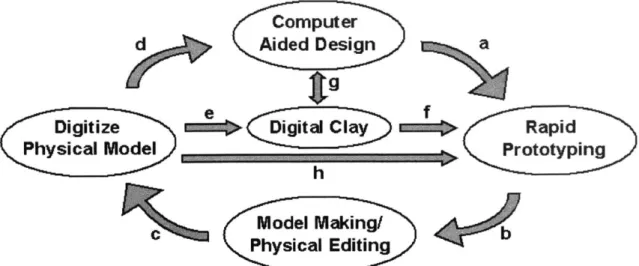
This thesis is a partial solution to the tremendous need for conceptual design tools that both suggest and allow the intuitive manipulation of product form. It is an extension of the work done in 1996. There are a number of methods available in today's commercial marketplace to perform each of the steps proposed in Robinson's thesis. The new design cycle is an integrated set of tools which enable the designer to rapidly generate and edit product concepts in the digital and physical world. The new cycle is shown as an integrated concept in Figure 2.3(a-h).
Computer
d Aided Design a
tg
Digitize o Rapid
Physical Model Prototyping
h
Model Making/ Physical Editing
Figure 2.3 (a-h) The Integrated Conceptual Design Cycle
In Figure 2.3.a, a model is designed in CAD and a rapid prototype is made. The designer or engineer can then modify the prototype if it does not match their intent, as shown in 2.3.b. Models can also be generated in the shop using traditional tools and materials instead of or in addition to rapid prototyping. The resulting model can be used for evaluation of form, fit and feel, and then digitized if the changes warrant it (2.3.c). The digitized part can then be passed to a CAD package and be modified or used as an underlay for geometry development (2.3.d). The model could also be brought into a digital clay environment (2.3.e), which allows a designer to modify or process a model with digital tools that work in similar ways to those found in a physical model shop. A digital clay application could also be used to generate the original 3D concept. Two options are available for export from the digital clay representation. The design can be brought into CAD for further refinement/finalization , or it can be made as a rapid prototype (2.2.g) for evaluation/further modification (2.2.g). Another useful path is to move
directly from digitization to rapid prototyping (2.2.h). This path allows a physical master or selected concept to be replicated and iterated.
The cycle provides workflow flexibility and facilitates interdisciplinary interaction. Marketing can obtain models at any stage of the process in a variety of forms and give direct feedback on the design. Engineers and designers can communicate with parametric solid and surface models, polygonal models, sketches, renderings, and physical prototypes. They can then offer
Chapter
3
Components and Integration
3.1 Components
The design cycle is composed of five components: computer aided design tools (CAD), digital clay, rapid prototyping (RP), hand-modeling-and-editing, and form digitization. The following sections provide a brief overview of the state of the art for each component, and conclude with the solutions used for this research. Further information about the products and companies listed in this chapter may be found at their respective websites, listed in Appendix 1.
3.1.1 Computer Aided Design (CAD)
Everyone is using CAD. In the late 1980's and early 1990's, CAD was primarily a 2D drawing and drafting tool. Early adopters of 3D CAD tools struggled with wireframe models, and had difficulty modeling complex freeform surfaces. Today's CAD packages are extremely powerful in comparison. This is largely due to advances in computer hardware, which have made desktop and portable workstations feasible and affordable. This section presents an overview of some of the popular 2D and 3D CAD packages used in conceptual design and the direction the industry is taking.
2D Software
Table 3.1 shows an overview of popular 2D design software packages and a brief description of their use.
Company
Product
Description of Use
drawing and drafting, making layouts
AutoDesk AutoCAD and underlays to scale
Adobe Photoshop image-editing and rendering
Adobe Illustrator vector graphics creation
Ashlar Incorporated Vellum Draft 2D wireframe modeling
AutoDesk is a large provider of 2D and 3D CAD software. Their AutoCAD product line has been a popular 2D drawing and drafting tool for over a decade. This product is especially popular among the architectural community.
Adobe has become very well known for their software solutions for Web and print publishing.
Photoshop is widely used for making photorealistic computer-renderings of concept sketches, as
well as for image-editing. Their Illustrator software is used widely for creating and refining concept sketches.
Ashlar Incorporated is a company that makes a range of 2D and 3D CAD software. Vellum, their 2D modeling package is very common amongst industrial designers for making underlays that are later used as a skeleton for 3D surface models.
The conceptual design cycle presented in this thesis is for 3D modeling, so a 2D software package was not explicitly chosen for use in this research.
3D Software
Table 3.2 shows an overview of popular 3D CAD software.
Company Product Description of Use
AutoDesk AutoCAD 2D and 3D design and drafting
3D Surface Modeling, Rendering,
AutoDesk 3D Studio MAX and Animation
Parametric Technology Pro/ENGINEER and Advanced
Corporation (PTC) Surfacing Extension 3D Solid and Surface Modeling
SolidWorks SolidWorks 3D Solid Modeling
IDEAS 8 and Imageware
SDRC Surfacer 3D Solid and Surface Modeling
3D Surface Modeling, Rendering,
AliasiWavefront Studio and AutoStudio and Animation
3D Rendering, Animation, and
AliasiWavefront Maya Surfacing
Robert McNeel and 3D Surface Modeling, Rendering,
Associates Rhinoceros and Animation
3D Surface Modeling, Rendering,
auto*des*sys FormZ and 2D Drafting
There are far too many packages available to list, but the above selections illustrate current trends in 3D CAD. In the world of independent product design firms, the most common solid modelers are Pro/ENGINEER and SolidWorks. Large companies often use a combination of off-the-shelf software and in-house CAD packages that are tailored to meet their specific needs as an organization. The common surface modelers among product design firms are Pro/DESIGNER (now known as the Pro/ENGINEER Advanced Surfacing Extension), AliasIWavefront's Studio and MAYA packages, and McNeel and Associates' Rhinoceros.
The following 3D CAD programs were used for this project: " Surface Modeling
Alias Wavefront AutoStudio and Maya Robert McNeel and Associates Rhinoceros " Solid Modeling
SolidWorks
One of the important characteristics of the design cycle is that any CAD package or combination thereof can be used, as long as a satisfactory STL file can be obtained for rapid prototyping. In general a software package's default settings are adequate for STL export, but for complex or high-order surface models tolerances may need to be set manually for distance or angular deviation from the model's surface. Software choice contributes greatly to the flexibility of the cycle. Combinations of surface modelers and solid modelers can be used. Other
non-conventional software (like digital clay) can be used. Any functionality the individual user requires can be obtained through proper software selection.
Digital Clay
A digital clay application called FreeForm from SensAble Technologies is used to sculpt conceptual models or modify digitized models. Built-in tools such as material addition and subtraction, mirroring and smoothing allow product concepts to be rapidly generated. The software uses the PHANToMm haptic interface to create a 3D Touchrm environment to enhance user interaction with both the FreeForm tools and the model itself.
3.1.2 Digitizing Form Models
Digitization is defined for the purposes of this thesis as the process of creating digital 3D
geometry from a physical object. This step is necessary when a physical (master) model is made or altered before a 3D electronic database has been generated or updated with changes.
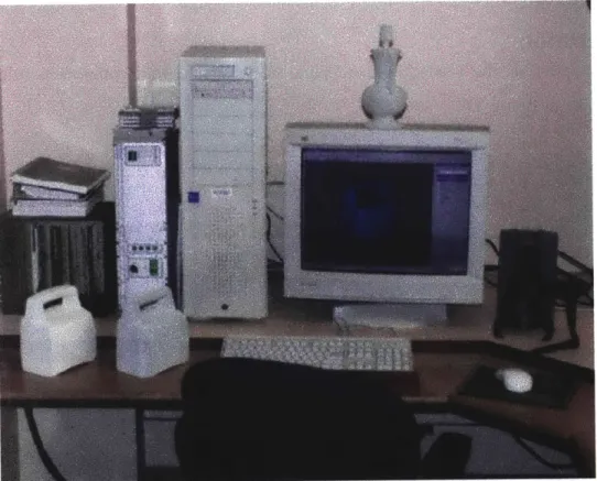
Workstation
In general, a large amount of computing power is necessary for high-speed CAD work, but digitization requires even more capacity. Models are often more than 20 megabytes before they are reduced as a final model. For this research, a dual-processor Intel Pentuimlll (512k L2 cache) was used, equipped with 1 gigabyte of 100 MHz RAM, and a Diamond FireGL 1 32 megabyte graphics accelerator. This machine was sufficient for most things, but a faster graphics card could have increased the speed of the work drastically.
Hardware
3D form digitization (scanning) takes a number of forms. The most common form in industry is approximate form reconstruction with CAD tools (surface modelers, solid modelers, or 2D drawing packages). This generally requires direct measurements to be made on the surface of the model with traditional measuring devices such as calipers [Robinson 1996]. Most designers and engineers do not have direct access to automated digitization techniques (described below), so this is the default method.
The form digitization process has been automated within the last 20 years through the
introduction of coordinate-measuring-machines (CMM), and optical range-finders. In order to properly digitize a conceptual form model, a great number of measurements are needed, with as high an accuracy as possible. Historically, the use of automated digitizing tools has been cost-prohibitive and not at all user friendly. Automated digitization systems are coming down in price significantly, and have become quite user-friendly.
There are two major types of digitization today: contact and non-contact. As its name suggests, contact-based digitization requires that something come in contact with the object during the digitization process. Non-contact digitizing methods use optical, ultrasonic, or magnetic means to generate a computer model without ever touching it. The digitization techniques and
Digitization Companies Description Technique
Uses multiple-jointed arm connected to a stylus which touches Mechanical . the surface of a model to collect points or curves in space.
Tracking Imersion Works in almost any environment and can digitize objects of any material.
The model is encased in wax and mounted on the table of a
. Dimension-Data CNC milling machine. A set of 2D scans are taken by a CCD Deconstruction (Steinbichler USA) camera as consecutive layers of a model are machined away.
Sets of boundary points are collected for each layer.
CyberWare, Polhemus, Range image(s) taken by triangulation of low-power laser-light
Laser Scanners Cyra, Hymarc, Real 3D, from 2 known viewpoints are used to generate a point cloud. Renishaw, Riegl, Vitana, Very accurate (0.5mm) point collection.
3D Scanners,
Dimension-Data Range image(s) through white-light triangulation are used to (Steinbichler USA), generate a point cloud. There is no limit to how many images White Light Cnolta r, sBEkn, can be used to make up an object. Extremely accurate (to
+/-CogniTens, Breukmann, 01 5mm).
Inspek, Wicks and Wilson
A magnetic field is used to triangulate spatial locations. Data
Magnetic (None investigated) quality may be affected by ambient magnetic field noise and metallic objects in the room. Lowest resolution of all the listed techniques.
Sound waves are transmitted and recieved by devices mounted Ultrasonic (None investigated) to the wall or ceiling to triangulate 3D point data. Inferior
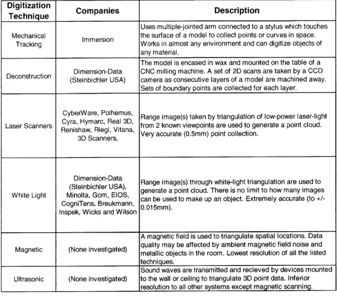
_resolution to all other systems except magnetic scanning. Table 3.3 Automated Digitization Techniques
The field of automated digitization is fairly broad and complex. To describe all of the options presented in Table 3.3 exceeds the scope of this thesis.
The requirements of a system for form digitization (scanning) in the context of this research are as follows.
" User friendly for people with moderate technical background (engineers and designers obtain
quality scans without help or supervision in a day or less).
" Accurately capture fine details as well as large free-form surfaces.
" Digitize a medium sized model (one cubic foot) and obtain an STL file for rapid prototyping
in one hour.
" Suitable for use in an office environment.
" Able to scan a wide range of model sizes (cell phone buttons or a large refrigerator exterior). * Portable (easy to move between rooms if necessary, and easy to ship).
Based on these requirements, several of the digitization techniques were eliminated without the need for further investigation. Deconstruction was eliminated because it destroys the original model, is not suitable for an office environment, and is limited in the size of the object that can be digitized. Ultrasonic scanning is not accurate enough for our purposes (approximately 1.5 mm), and generates noise that could be annoying to those around the machine. Magnetic scanning devices are typically less accurate than ultrasonic scanners.
The three most popular scanning techniques are mechanical tracking, laser scanning and white light scanning. Mechanical tracking devices like the Immersion Microscribe require that the user touch a stylus to the model to collect points. The device has a very small footprint (6" x 6"), and is capable of digitizing a workspace of up to 66 inches. The user is able to collect data outside of the direct line-of-sight, such as undercuts or holes. These scanners are fairly accurate, and are quite inexpensive (less than $5,000). Unfortunately, this method is very time consuming. Digitization time is highly dependent on the complexity of the model (more features require more points, which translates into more time). It is at least an order of magnitude slower than optical techniques like laser and white light triangulation for most applications.
Laser and white light scanners are similar in functionality. They are both non-contact optical devices that scan complex geometry easily. They are both very accurate and are available in portable form. Systems are available at a broad range of prices, based on features like accuracy and maximum workspace size.
For this research, a Steinbichler Comet 250 white light scanner was chosen. While it is more expensive than some laser scanners and white light scanners, it best suits the needs of this
application. The halogen light it emits is harmless to humans, and it is small enough for use in an office environment (it requires a footprint slightly larger than an average office copier). It is widely used in the automotive industry for clay model scanning because it is extremely accurate (± 0.06 mm) and achieves a point spacing of 0.3 mm. Models are scanned in patches which are then merged via software, making it well-suited to the conceptual design cycle. Once a model has been digitized, the user can capture changes by scanning patches that include the modified
areas. These patches are then merged into the original dataset. The scanner is discussed as an integrated component of the conceptual design cycle in section 3.2, and its use is detailed with respect to applications in chapter 4.
Software
The 3D scanner uses third party software to align, merge, and edit the scan "patches." For this project, the PolyWorks/Modeler software suite by InnovMetric was used. PolyWorks/Modeler is a comprehensive software package that allows the user to build high-resolution polygonal models from 3D digitizer data. It has tools that help generate smooth, accurate, and watertight models for applications such as CNC machining, rapid prototyping, reverse engineering, and finite-element analysis. PolyWorks/Modeler is used in fields such as the automotive, aerospace, and consumer products industries. Other companies offer software packages that contain similar tools. PolyWorks/Modeler was included as part of the package with our 3D scanner.
In order to properly complete the conceptual design loop with 3D form digitization, a second software package was used to generate Igesl28 NURBS (Non Uniform Rational B-Splines) surfaces from scan data. Few companies offer software to accomplish this task. The field is relatively new, so it was difficult to make an educated decision about which company to use. Two major players appear to be Raindrop Geomagic and Paraform. Geomagic Studio by Raindrop Geomagic was used to edit and seal point clouds and polygonal models, smooth
surfaces, and generate NURBS surfaces during this project. Paraform would have served equally well for our purposes. The file formats used the most during this project were STL for rapid prototyping, and Iges 128 to move from scan data to CAD software.
3.1.3 Rapid Prototyping
For the purposes of this thesis, rapid prototyping (RP) refers to the automated generation of a physical object from a computer model. Most rapid prototyping methods require a polygonal representation of part geometry such as STL, which has become a common file export option for
most CAD packages. Third party software is then used to slice the parts into thin cross-sections, and the part is built up layer by layer. One exception is CNC machining, which generally requires toolpaths in a form such as G-code.
Most companies use RP within their design process. Rapid prototyping holds different meanings for different people, and none of its manifestations constitutes a global solution for all
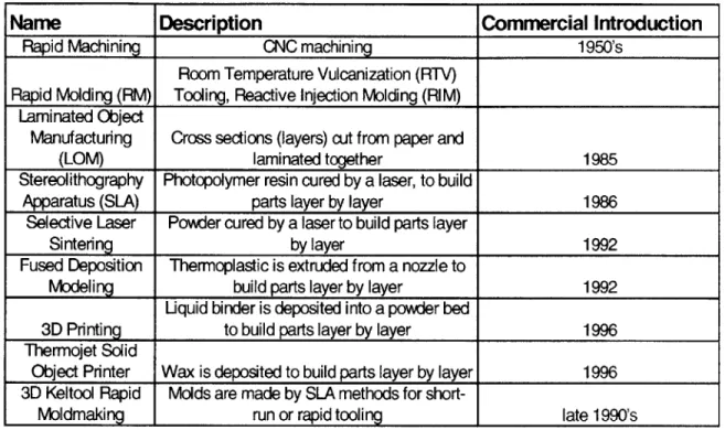
applications. The definition of RP has changed somewhat in recent years, as new technologies have become more refined and accepted by industry. In 1991, popular RP techniques included computer numerically controlled (CNC) machining, RTV tooling, SLA, and SLS [Wall 1991]. Some of its current forms are listed in table 3.4.
Name Description Commercial Introduction
Rapid Machining CNC machining 1950's
Room Temperature Vulcanization (RTV) Rapid Molding (RM) Tooling, Reactive Injection Molding (RIM)
Laminated Object
Manufacturing Cross sections (layers) cut from paper and
(LOM) laminated together 1985
Stereolithography Photopolymer resin cured by a laser, to build
Apparatus (SLA) parts layer by layer 1986
Selective Laser Powder cured by a laser to build parts layer
Sintering by layer 1992
Fused Deposition Thermoplastic is extruded from a nozzle to
Modeling build parts layer by layer 1992
Liquid binder is deposited into a powder bed
3D Printing to build parts layer by layer 1996
Thermojet Solid
Object Printer Wax is deposited to build parts layer by layer 1996 3D Keltool Rapid Molds are made by SLA methods for
short-Moldmaking run or rapid tooling late 1990's
Table 3.4 Common Methods for Rapid Prototyping and Tooling
Table 3.4 is considerably larger than it was just a decade ago. Although most of the technologies listed above existed in some form, many were not commercialized until the early to mid-1990s. In fact, it has been possible to create physical parts from computer models without machining for about a 15 years. The major differences between today's rapid prototyping landscape and that of the early 1990s are availability, ease-of-use, quality, and price. When people talk about RP today, they are usually not referring to RTV molding or RIM, but rather to SLA, FDM, 3DP, LOM, SLS or the CNC machining of soft materials like urethane foam or Ren Shape. Processes such as RTV and RIM are still valuable tools in the context of product design and manufacturing, but are no longer considered "rapid."
The oldest "modern" rapid prototyping technology is CNC machining, which originated in the early 1950s. The first CNC milling machine was developed in MIT's Servomechanisms Laboratory out of a program funded by the United States Air Force [Jaikumar 1988]. This process remains the standard for functional and high-precision prototyping, though some of the layered methods are now capable of tolerances of ±0.001 in/in in the X, Y, and Z directions, and can create features that would be infeasible with 3-axis CNC milling or CNC turning.
Technologies that were once predicted to become "'desktop manufacturing processes' that will put manufacturing in the hands of the designer" [Wall 1991] have become industry standard processes for prototyping. For example, SLA models are commonly used to enhance communication and evaluation of a design at strategic points in the development process. Rapid prototypes serve as visual models, functional models, or both, depending on which process is chosen and what the needs of the design team are at the time. Auto makers often run tests of new engine designs by creating functional prototypes through the SLS process, and aesthetics may be evaluated at the same time.
The gold standard for rapid prototyping today is still SLA, one of the oldest RP technologies. It is not the fastest technique available, but generally has high resolution and accuracy, a nice finish, high strength, and a good selection of materials from which to choose. 3D Systems of Valencia, CA has been selling SLA machines since 1986. Their technology uses a laser to cure thin layers of photopolymer, which are built up to form the part. They offer an array of polymers with varying material properties. 3D Systems' 3D Keltool rapid mold making machines create SLA-like molds for injection molding and die casting that can withstand millions of cycles. Many rapid prototyping techniques are now clean and simple enough for office use, and are of significant interest to this research. They include the 3D Systems Thermojet solid object printer, the Z Corporation Z402 3D Printer, Stratasys FDM machines, and the Objet Quadra- a new photopolymer 3D printer.
3D Systems (mentioned above for their SLA machines) also makes an office-compatible 3D printer called the Thermojet solid image printer that prints wax parts with no mess.
Stratasys, of Eden Prairie, MN, offers Fused Deposition Modeling (FDM) machines. This RP method extrudes a thermoplastic or investment casting wax through a nozzle to build parts up layer by layer. A support structure is needed, and is generated automatically by software and
removed when the part is done. A support material is now available that dissolves in a water-based solvent, so the finish of the part is not compromised by connections to the supports. A new technology is on the horizon from an Israeli company called Objet Geometries Ltd. (Rehovot, Israel). Objet recently announced an innovative three-dimensional ink jet printer. The Quadra, a pre-production prototype that will introduce their technology in the USA, uses a process based on ink jet printing technology. The material is a proprietary photopolymer developed by Objet. It is said to require no post-cure or post-processing, which could make it a potential in-house alternative to SLA.
A Z Corporation Z402 3D printer was used in this research. The Z Corporation (ZCorp) 3D printer is based on 3DPTM technology invented at the Massachusetts Institute of Technology,
patented by MIT. ZCorp licensed this technology in 1994, and installed its first beta unit in December 1996. The ZCorp. Z402 printer has two materials currently available:
cornstarch/cellulose-based ZP1 1 and plaster (microstone) powder called ZP100. ZCorp is working to develop new powders with diverse material properties.
Parts emerge from the powder bed of the Z402 in the "green" (wet) state, and are usually baked to evaporate the water from the binder solution out of the part. The parts can be left untreated for quick evaluation, or can be coated with a variety of resins and sanded to achieve different levels of surface finish.
The ZCorp machine was chosen for four primary reasons. First, it is currently the fastest layered manufacturing rapid prototyping system. Second, models can be easily modified using traditional forming techniques in the "green" state, and a range surface finishes can be obtained. Third, the cornstarch powder used in this research (ZPl 1) is non-toxic, not skin-irritant, not prone to static electricity buildup and does not appear to corrode tools. It also has good working characteristics, which are discussed in the next section. Fourth, the machine is clean and quiet enough for use in an office environment, though it hums like a medium sized air purifier and requires a vacuum for cleanup, which could be distracting for office-workers.
3.1.4 Modeling Materials and Tools
This section presents a brief overview of form modeling within conceptual design. Those who are familiar with model-shops and the use of the standard modeling materials listed in table 3.5 may wish to move on to section 3.2, in which the cycle is covered as an integrated system. Within conceptual design there are two types of form modeling: sketch modeling and visual modeling. Sketch models are used to quickly convey concepts without going into any more detail than necessary. The evaluation of very early form concepts is often done through a series of sketch models. Sketch models are usually monochrome, so that decisions are not weighted by color preferences. The surface texture is often left rough so that the person evaluating the design knows immediately that the models are intended as form prototypes and not the final design. This information is important to convey because it helps keep everyone involved in design decisions thinking in the same stage of the process. Miscommunication of intent can lead to frustration and unnecessary extra steps in the design process.
After the design has advanced substantially, variations may be expressed through a short series of visual models. Visual models usually represent the look of the real product, including color and texture. If you were to look at the model without touching it, you would not know it was not the real thing.
There are many different types of modeling materials for different applications. Table 3.5 shows an overview of the most popular materials that are hand-worked and/or machined to make form models.
Material Use Characteristics
Expanded Primarily sketch A fairly inexpensive material for sculptural forms or models Polyurethane Foam modeling that need to be solid. Easy to cut and shape with hand tools.
(blue or pink)
Cardboard Sketch modeling Creates strong structures when folded. Cost effective way to
(corrugated or or visual Cre stcuresw
honeycomb) modeling build large sketch models.
Sketch modeling Similar to cardboard. Higher degree of finish or refinement
Foam Core or visua than corrugated cardboard can accommodate.
Structural Foam Refined sketch Very good for sculpting form. Comes in a large range of
(yellow urethane) modeling or densities. Models have a textured (porous) surface. Obtaining visual modeling a smooth finish requires considerable effort.
Properties similar to urethane foam. Holds fine details very Balsa Foam Visual Modeling well. Main disadvantages are that it is somewhat brittle, is very
dusty to work with, and corrodes tools.
Finer texture and harder surface than urethane foam. Holds edges and corners very well. For hand working or machining Ren Shape@ Visual Modeling (especially CNC). Ideal for visual models where finish matters.
Available in a wide range of densities. Dust is somewhat abrasive.
Hard enough to hold fine carving details and soft enough to Basswood Visual Modeling work easily. Relatively easy to work compared to other types
of wood. It is fairly easy to finish to look like plastic. Table 3.5 Common Form Modeling Materials
Many designers move from 2D sketches to "blue foam" (blue or pink expanded polyurethane foam insulation for building construction) for quick concept mock-ups or form models. This foam is a very popular medium because it can be cut with a hot-wire tool, carved, sawed, sanded, joined, machined, and painted. However, chips and dust are easily charged with static electricity
so they stick to everything in the shop, which makes cleanup difficult. Blue foam also dents easily, which makes it awkward to handle and clamp down while working. It tears easily if a rough sandpaper is used or if proper cutting techniques are not carefully employed. Many model makers are frustrated by how delicate it is because otherwise it is an inexpensive material that works easily. This and other types of insulation foam are generally considered a quick, low-quality form modeling material. Many industrial designers and model makers are adamant about not using it at all.
Corrugated cardboard and foam core are similar in their working characteristics, but foam core has a better surface finish. These materials are used for both sketch modeling and visual
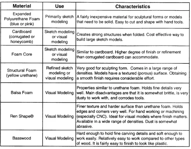
modeling. Foam core and cardboard were not used for the purposes of this thesis, but are mentioned because they are a valid medium to use within the design cycle and should not be overlooked. Figure 3.1 shows what some of the most common sketch modeling materials look
like (photo courtesy of the 2.744 website [6]).
Figure 3.1 Common Sketch Modeling Materials
Counter Cclockwise from Left: Pink Foam, Corrugated Cardboard, Honeycombed Cardboard, and Foamcore (courtesy of the 2.744 website)
Structural urethane foam, or "yellow foam," is the most popular material for refined form exploration amongst the companies interviewed. This material is easily carved or machined, and holds detail fairly well. The unfinished surface texture serves to hide small imperfections in the surface of the model. The density of the material can be chosen to fit the required surface finish, hardness and strength of the model. The material can be sanded and finished to make a realistic model, though this takes considerable effort. Rapid prototypes like SLA models are a frequently finished to make such realistic models today. Designers typically make a series of form models by hand or CNC machining and present them in a single color without disguising the texture of the foam.
Balsa foam has very similar characteristics to urethane foam, but is dustier to work with, more brittle, and corrodes tools. For these reasons many designers and model makers try to stay away from it.
Basswood is hard enough to hold fine carving details, but works easily. Its short grain makes it relatively easy to work along or across the grain. Basswood is much easier to finish than materials like urethane and balsa foams, and is much more like Ren Shape in its characteristics.
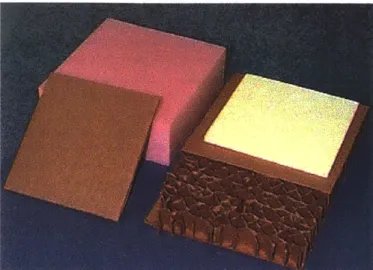
It is usually used for realistic visual models further along in the design process, and has lost some popularity due to the different densities of Ren Shape (described below) available. Figure 3.2
shows basswood, balsa foam, and urethane foam.
Figure 3.2 Common Visual Modeling Materials
CounterCclockwise from Left: Basswood, Balsa Foam, and Urethane Foam (courtesy of the 2.744 website)
Ren Shape@ is a relatively new product from Ciba Specialty Chemicals, and has gained
incredible popularity among the model making community. Ren Shape was designed specifically to have good machining properties, and is available in a variety of densities and hardnesses (ten different board materials). It is generally stronger than urethane and balsa foams, and sections can be glued together and then machined or carved.
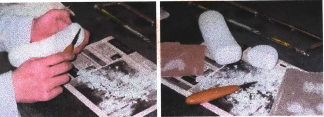
With the widespread acceptance of rapid prototyping in product design, new materials and modeling processes are being developed. Of particular interest is the ZCorp cornstarch and cellulose material for 3D printing, ZP1 1. Parts made of ZP1 1 by the Z402 3D printer have
working characteristics somewhere between blue foam and urethane foam. Freeform surfaces are easily carved using traditional modeling tools, and the material holds edges and lines almost as well as yellow urethane foam. Material can be added using traditional joining methods. Polyester filler material like wood putty and Bondo can be used, though they cure to be quite a bit harder than the 3D printed material.
ZPi1 is non-toxic, non-corrosive, and non-static (which makes it easy to clean up). Materials Safety Data Sheets for ZP1 1 powder and ZB7 binder are available upon request from Z
Corporation. The major drawback to this material is that parts cannot get wet, and if bulky parts are not properly dried soon after coming out of the print-bed, the may crack as the internal material dries and shrinks. This material presents a new approach to model making. Instead of building geometry from scratch for every model using subtractive processes, the part can be made directly from a 3D CAD database by the 3D printer and then modified to create a new concept, as shown in figure 3.3.